VOTRONIC Automatic Charger - Solarlink GmbH, preiswert und ...
VOTRONIC Automatic Charger - Solarlink GmbH, preiswert und ...
VOTRONIC Automatic Charger - Solarlink GmbH, preiswert und ...

Create successful ePaper yourself
Turn your PDF publications into a flip-book with our unique Google optimized e-Paper software.
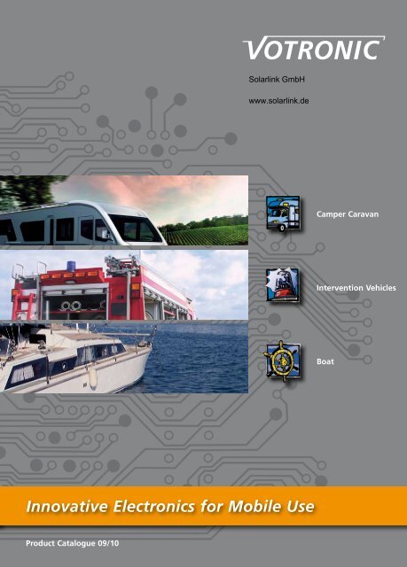
<strong>Solarlink</strong> <strong>GmbH</strong><br />
www.solarlink.de<br />
Camper Caravan<br />
Intervention Vehicles<br />
Boat<br />
Innovative Electronics for Mobile Use<br />
Product Catalogue 09/10
General Information<br />
A Word on the Company History<br />
A Word on the Company History<br />
<strong>VOTRONIC</strong> Richard Schmelz Elektronik has been fo<strong>und</strong>ed in Grebenhain/Germany in 1987.<br />
The business activities of the company are the development and production of electronic<br />
units for campers, caravans and boats. The first product series were tank level displays, units<br />
for battery control and automatic battery chargers.<br />
Soon, <strong>VOTRONIC</strong> expanded and extended the product range. Due to the early application<br />
of microprocessors, the functional features of the units were improved resulting in high<br />
reliability and facilitation of the production at the same time. In 1993, the products had<br />
been improved for professional application in ambulance cars (intervention vehicles). Since<br />
particular requirements of the customers were always considered, the range of customized<br />
units became more and more important. The great demand for <strong>VOTRONIC</strong> products involved<br />
an extension of the capacity of production and stock.<br />
The new branch rainwater recovery became interested in <strong>VOTRONIC</strong> products, and the<br />
second product series covering digital displays and control units for rainwater cisterns was<br />
established. Many years of experience in level measurement technology for campers are the<br />
basis for further innovations. In 1997, <strong>VOTRONIC</strong> became established as reliable supplier<br />
for OEM products and managed that a renowned customer became the market leader for<br />
the range of rainwater.<br />
In 1998, the progressive expansion of the company required a new legal form as well as<br />
a new building. In the year 2000, the quality assurance system DIN ISO 9001 was implemented<br />
to govern and guarantee the complex production processes and the high quality<br />
standard also in future. Additional products for fire fighting and special purpose vehicles<br />
and the third product series in the range intervention vehicles was created.<br />
In 2003, the course for a successful future has been set by calculated economical measures.<br />
Increasing competitiveness secured further market shares, and an extension of the production<br />
facility was required. In 2005, further investments in advanced production machinery<br />
allowed execution of even large orders with the proven high quality standard.<br />
Already in the end of the year 2005 and after a long preparatory phase in close cooperation<br />
with the suppliers for electronic and mechanic components the conversion of the production<br />
to RoHS conform products was realised. A conspicuous change in the production of<br />
electronic appliances was the conversion of the soldering processes to lead-free soldering.<br />
A lead-free production requires rethinking of the entire production chain. Therefore, additional<br />
production and test equipment was acquired in 2006/2007 to ensure an execution of<br />
the production processes, which became more difficult, in the usual high quality.<br />
The Company‘s Philosophy<br />
High quality of the produced products as well as commitment tying the customer to the<br />
supplier for a long time is the basis for successful business activities. So<strong>und</strong> growth in manageable<br />
steps, collegial leading of the personnel, as well as involvement and motivation are<br />
the guidelines for success in the hart fights for competition.<br />
Everything we do, we are doing for the benefit and satisfaction of our<br />
customers.<br />
Our Portfolio<br />
All electronic units being distributed by our company are developed and produced at our<br />
site in Germany.<br />
Since development as well as production of the units is effected in our house, we are able<br />
to respond quickly to the customers‘ requirements. Customized units and special executions<br />
up to OEM products are developed in close cooperation with our customers and realised<br />
in due time. Further activities of our company are component insertion, as well as checking<br />
and production of componentries and complete units as subcontractor.<br />
Our Efficiency<br />
We deliver the complete electric equipment of a mobile home in high quality. The company<br />
producing these quality products formed the name VOTRONC by so<strong>und</strong> cooperation, reliability<br />
and by keeping the delivery schedule. Due to our well-equipped stock, a sufficient<br />
quantity of our products is always available. Even in boom times, we are always in a<br />
position to respond quickly to our customers’ requests owing to our flexible electronics<br />
production. Good logistics combined with a reliable forwarding agent ensure the short-term<br />
delivery of our products.<br />
Our Commitment<br />
Particularly today, the education of young people is a social commitment, and is thus a<br />
matter of course for us. The vocational training in the special field electronics ensures the<br />
future of our company and safeguarding of jobs in our country. Furthermore, we are active<br />
in the further development of the charging technology for lead batteries by our involvement<br />
in superior institutions, such as the DIN committee for fire protection.<br />
Today, about 45 employees are busy with the series production of our electronic units for<br />
the product ranges mobile application and rainwater recovery for delivery to renowned<br />
national and international customers. Known as a competent OEM supplier, special executions<br />
and customized units are developed and produced in large-scale manufacture.
Content<br />
Charging Technology 4-14<br />
Battery <strong>Charger</strong>s<br />
Our Service<br />
Our service department gives advice and support to you, no matter if it concerns technical<br />
questions regarding the <strong>VOTRONIC</strong> products or problems regarding an application in the<br />
vehicle. If your local garage does not dispose of the required technical equipment for your<br />
vehicle, do not hesitate to contact us. Our technicians are always at your disposal to resolve<br />
your technical problems. However, you are kindly requested to arrange a date by phone.<br />
We are available at any time: technik@votronic.de<br />
Internet:<br />
Our website presents the complete <strong>VOTRONIC</strong> program, clearly arranged and comprehensively<br />
described. Furthermore, the website informs of news and interesting details concerning<br />
our company and our products, as well as of the dates of shows we are participating<br />
in. Our catalogue can be ordered online, or it can be downloaded.<br />
Product Information and Details concerning Orders<br />
for Boat Application<br />
On principle, all our products are also appropriate for application in boats. The products in<br />
our price-list being marked with „x“ and „o“ are particularly modified for boat application,<br />
i. e. they are equipped with a humidity-proof electronic system etc. The price of these units is<br />
between 5 % or 10 % above the list price of the valid price list. When ordering these products,<br />
please add „1“ in front of the respective order number.<br />
Quality Products Made in Germany<br />
Only obtainable at specialized dealers<br />
Quality Management<br />
produced according to<br />
Batteries 15<br />
Voltage Transformers 16-17<br />
Power Inverters<br />
Solar Technology 18-21<br />
Charging Controllers<br />
Displays<br />
Level Measurement<br />
Technology 22-27<br />
Displays<br />
Combination Units<br />
Switching Components<br />
Transmitters<br />
Measuring Devices<br />
and Displays 28-33<br />
Battery Computers<br />
LED and LCD Modules<br />
Switch Panels<br />
Fuse Panels<br />
Peripheral Units 34-39<br />
Cutoff Relays<br />
Battery Controllers<br />
Battery Refreshers<br />
Circuit Distributors<br />
Accessories 40-43<br />
For Your Guidance<br />
In order to help you to find details, our products can be<br />
identified by symbols. These symbols show the preferable<br />
application ranges…<br />
Camper Caravan<br />
Electronic-Systeme <strong>GmbH</strong> & Co. KG<br />
Ilbeshäuser Straße 4<br />
D-36355 Grebenhain<br />
Phone: 00 49 (0) 66 44/96 11-0<br />
Fax: 00 49 (0) 66 44/96 11-20<br />
e-mail: info@votronic.de (General Requests)<br />
verkauf@votronic.de (Sales Department)<br />
technik@votronic.de (Technical Support)<br />
Internet: www.votronic.de<br />
Imprint<br />
Any indication in this catalogue corresponds to the state of the art at the time of<br />
publication. Subject to misprints, errors and technical modification without notice.<br />
Copyright <strong>VOTRONIC</strong> Grebenhain 8/08. All rights reserved.<br />
Design Concept and Realisation<br />
designbüro, 36341 Lauterbach<br />
Intervention Vehicles<br />
Boat
<strong>VOTRONIC</strong> <strong>Automatic</strong> <strong>Charger</strong>s<br />
Professional <strong>Charger</strong>s for Mobile Use<br />
Batteries and <strong>Charger</strong>s<br />
The battery is the central element of the vehicle’s electric system. Utmost attention has to be<br />
paid to it concerning maintenance and care, and, above all: It has to be charged correctly.<br />
This is particularly true to vehicles with two battery circuits, such as special purpose vehicles,<br />
ambulance cars, campers or boats, where a special auxiliary battery supplies the electric<br />
appliances, systems and equipment on board. The charging state of this supply battery decides,<br />
which electric appliance can be switched-on and how long it can be switched-on. The<br />
lifetime of the battery is decisively influenced by the battery type, the charging and discharging<br />
processes, by eventual total discharge and also by the used charging technology.<br />
This concerns the range of campers and boats, as well as intervention vehicles, where the<br />
electric equipment is very often decisive for life and limb.<br />
When charging a vehicle battery, it is important, that 100% output is always available and<br />
that the charging current and the charging voltage are kept to the correct values during<br />
the complete charging cycle. In keeping with the times, this can only be achieved with units<br />
according to advanced switch mode technology (SMT), since -in contrast to former transformer-rectifier<br />
units- they distinguish by complete and precise adjustment of all instabilities<br />
(low voltage, deviating frequency and sine curve, power failure). Due to an exactly defined<br />
characteristic line of charging IU1oU2, the <strong>VOTRONIC</strong> automatic chargers in switch mode<br />
technology allow quick and effective charging of lead-acid, gel and AGM/fleece batteries,<br />
treating the battery careful at the same time. This reliable concept of charging technology,<br />
which has emerged from the close cooperation with leading battery and vehicle manufacturers,<br />
can be used for a wide range of applications on the one hand, and, on the other<br />
hand, it can despite be adapted to the requirements of the user.<br />
The units are designed for installation in campers, boats, ambulance cars and special purpose<br />
vehicles, and they are particularly suitable for stationary installation in the industrial<br />
range.<br />
Which battery is the right one?<br />
Normal starter batteries are not designed for cyclic load. Thus, they cannot be recommended<br />
as board batteries. For the load in campers, intervention vehicles and boats we are exclusively<br />
offering cycle resistant batteries (see page 15).<br />
Which <strong>VOTRONIC</strong> charger is the right one?<br />
The units of series “Pb” are designed for the leisure range, such as campers and boats,<br />
while the professional series “VAC” is particularly adapted to the requirements in intervention<br />
vehicles to ensure permanent readiness for use.<br />
For a long time, battery manufacturers were indicating the recommendable charging capacity<br />
for their batteries with 10 % of the used battery capacity (Ah).<br />
Example:<br />
Nominal capacity of battery 100 Ah, 10 % of it = 10 A charging current should be supplied<br />
by the charger.<br />
Contingent on increase of comfort and more electrical consumers in the vehicle, nowadays<br />
a value of about 14 % is more realistic. The reason is the simultaneous supply of the consumers<br />
(refrigerator, lighting, TV) during battery charging, which is resulting in a reduction<br />
of the actual charging capacity. Consequently, this consumption has to be considered for<br />
dimensioning of the charger’s charging capacity by up to 40 % to achieve a sufficient and<br />
quick charging, treating the battery carefully at the same time. On principle, the charger<br />
should never be chosen “too small”, because overcharging of the battery is not possible<br />
and the number of consumers is increasing continuously.<br />
Due to their intelligent full battery recognition, <strong>VOTRONIC</strong> chargers are covering a very<br />
wide range of battery capacities. Further details concerning the values can be drawn from<br />
the unit tables.<br />
Apart from insufficient charging by an inappropriate charger, the total discharge should not<br />
be <strong>und</strong>erestimated in connection with quick ageing or premature failure. Total discharge<br />
of a 12 V lead battery and consequently damage starts already from a battery voltage of<br />
less than 10.5 V. Very often, this is caused by consumers, which have not been switchedoff,<br />
“hidden” discharge in the mA range by tracking current in case of humidity despite of<br />
disconnected main switch, electromagnetic stop valves of heaters or “silent” consumers,<br />
such as clocks, control panels and units in stand-by mode.<br />
The <strong>VOTRONIC</strong> delivery program comprises different battery control units, such as battery<br />
computer and battery protector (protection against total discharge) to prevent an imminent<br />
total discharge of the supply battery.<br />
If a battery shall be replaced, it is recommendable to check the existing power supply<br />
concept and to develop an energy balance to be able to considering also consumers being<br />
eventually installed later.<br />
Following is an example for calculation of any consumer, which shall help the user to<br />
develop his energy balance:<br />
Example:<br />
2 Halogen lamps, 12 V (Volts)/30 W (Watts), each:<br />
Capacity (total) 60 W, divided by the voltage 12 V = current intensity 5 A (Amperes).<br />
Time of use / day in hours (h) e.g. 4 h x 5 A = 20 Ah<br />
This calculation has to be made for each consumer. The total capacity is the sum of all<br />
results. In case of lead-acid batteries, this value is multiplied by the factor 1.7, in case of<br />
AGM/fleece batteries, the value is multiplied by the factor 1.4, and in case of gel batteries,<br />
the value is multiplied by the factor 1.3. The result is the minimum nominal capacity (in<br />
ampere-hours Ah), the battery should have.<br />
Most Important Features of the <strong>VOTRONIC</strong> <strong>Automatic</strong> <strong>Charger</strong>s<br />
= No. of charging program adjustable<br />
(Type acid, gel, AGM) see page 7<br />
= <strong>Automatic</strong> battery regeneration<br />
= Power pack function (battery replacement)<br />
= Equalization function<br />
(compensation charging of the cells)<br />
= Connection remote control/remote indicator<br />
= Battery capacity (size) adjustable<br />
= Charging current distributor for<br />
one or several batteries<br />
= Power limit function<br />
(Reduction of the mains/charging capacity)<br />
= Silent run function (reduction at night)<br />
= Temperature sensor is included in<br />
the standard delivery<br />
= Temperature compensation<br />
= Voltage sensor (in case of very long charging cables)<br />
= Electronic system humidity-proof<br />
= Unit waterproof and dustproof<br />
= Protection class II
<strong>VOTRONIC</strong> IUoU Charging Function<br />
Quick, reliable and careful treatment of the battery<br />
Charging Technology<br />
Features of the <strong>VOTRONIC</strong> <strong>Automatic</strong> <strong>Charger</strong>s, Series Pb and VAC:<br />
The units are distinguished by high operating safety and permanent readiness for operation.<br />
High-quality charging technology and robust power electronics in connection with intelligent<br />
microprocessor control ensure exact observation of charging voltage rates, charging<br />
current rates and charging time, and the battery life is extremely extended.<br />
• All-automatic continuous operation, permanently ready for operation.<br />
• The charging voltage is exempt from peaks, and it is controlled in such a way, that<br />
overcharging of the batteries is excluded. Thus, trouble-free operation and simultaneous<br />
supply of the units being connected to the vehicle’s board mains supply is also ensured.<br />
• Depending on the unit type different charging programs (stored in the EEPROM) can be<br />
adjusted for optimum charging and conservation of charge of acid-/lead-acid, gel/dryfit<br />
and AGM/fleece batteries in plate technology and in ro<strong>und</strong>-cell technology (such as<br />
OPTIMA batteries).<br />
• Units with integrated charging current distributor are able to charge individual and<br />
several batteries at the same time. The higher charging capacity will be automatically<br />
supplied to the battery (bank) showing the lower charging state. From the same charging<br />
level, simultaneous charging will be effected. On request and with most of the Votronic<br />
chargers this built-in charging current distributor allows selection of an own charging<br />
program for starter batteries by means of an adjustable switch in order to ensure charging<br />
with the full current rate and immediate availability. Simultaneous charging of combinations<br />
of acid/gel/AGM batteries together with starter batteries is also possible. Even<br />
strongly varying capacity and charging states of the batteries are admissible, and they<br />
are recognized automatically by these units with integrated charging current distributor.<br />
• Almost all of the chargers are equipped with an auxiliary charging port “S” with current<br />
and voltage reduction. In case of extended stop periods, this might contribute to support<br />
charging and conservation of charge of the vehicle’s starter battery to ensure its starting<br />
capacity.<br />
• The full recognition of the battery includes evaluation of several criteria and ensures a<br />
safe and careful full charging with automatic commutation to conservation of charge.<br />
The units are recognizing automatically, if charging current for the battery (batteries) is<br />
concerned or only supply current of connected consumers. Unnecessary long charging of<br />
a battery, which is already fully charged, is thus avoided (gassing, battery load).<br />
• The simultaneous supply of connected consumers during charging and conservation of<br />
charge (parallel/floating operation) is implemented and will be considered by the chargers.<br />
For protection of the consumers, the voltage is limited during any charging mode<br />
and operating mode.<br />
• The temperature compensation (automatic adaptation of the charging voltage to the battery<br />
temperature) improves full charging of the weaker battery in case of low outside temperatures<br />
and avoids unnecessary battery load and gassing in case of summery temperatures. In<br />
Votronic chargers it is also adapted to the corresponding battery type/characteristic line of<br />
charging. For reasons of safety, a gradual reduction of the charging capacity is effected in case<br />
of temperatures above 45 °C, and in case of 50 °C (battery overheating), the charging current<br />
will be disconnected. Reconnection will be effected automatically after cooling down.<br />
• The automatic compensation of voltage loss on the charging cables ensures precise keeping<br />
of the charging voltage at the battery. Powerful unit versions allow connection of<br />
voltage sensor lines, which is recommendable in case of very long charging cables.<br />
• Short charging time and high capacity storage.<br />
• Safe and careful preliminary charging, even of batteries being totally discharged or<br />
extremely discharged.<br />
• In case of extended stop periods, the automatic battery regeneration being effected<br />
twice a week decomposes acid accumulation in the battery, which is decreasing the<br />
performance.<br />
• Clearly arranged indication of the operating state by light-emitting diodes.<br />
• Full charging capacity is achieved by cooling of the units by convection and by means<br />
of a fan with temperature and speed control. If this is not sufficient in case of very high<br />
temperatures (such as due to adverse installation and cooling conditions), further charging<br />
is attempted with gradual reduction of the capacity.<br />
• The silent run function ensures noise optimisation during night operation. At the touch of<br />
a button, the cooling fan will change to a steady low noise speed with slightly reduced<br />
charging capacity (reduction at night).<br />
• The power pack function allows continued supply of the consumers, also without battery,<br />
such as in case of battery replacement, maintenance or emergency operation.<br />
• If the individual cells of lead-acid batteries show varying charging states due to insufficient<br />
charging or total discharge, the equalization function effects a readjustment to the<br />
same charging level by means of a characteristic line of charging IUIU. Since this is a kind<br />
of “living cell therapy” for the battery, it should be released manually and only in case of<br />
need.<br />
• If necessary, the mains input power, and thus the charging capacity of powerful chargers,<br />
can be adjusted to a lower value by means of the “Power Limit” function. This allows an<br />
operation, even with weakly protected country current supply at campsites or Marina, as<br />
well as with low capacity generators.<br />
• The mains side of all <strong>VOTRONIC</strong> chargers is equipped with a commutation to sinusoidal<br />
power consumption (PFC), and they are working according to the switch mode technology<br />
(SMT). They cope with even strong deviations of supply voltage, mains frequency and<br />
sine curve and thus ensure full charging capacity <strong>und</strong>er adverse conditions, even at the<br />
far end of a weak power supply.<br />
• The SMT technology supplies “true” direct current without ripple noise, power peaks etc.<br />
This avoids unnecessary heating of the battery and allows trouble-free operation of even<br />
sensitive consumers during the charging process.<br />
• Built-in on-board mains suppression filters ensure unproblematic parallel operation<br />
of dynamos, motor generators and wind-driven generators, solar systems etc. at one<br />
battery.<br />
• Intelligent microprocessor control systems using SMD technology completed by robust<br />
power electronics ensure high operating safety. This includes also safety timers working<br />
in the backgro<strong>und</strong>, which abort the individual charging phases in case of failure (such as<br />
short-circuit of the cells) to produce safe conditions.<br />
• Unattended charging and standard protection against overload, overheating, overvoltage,<br />
wrong polarization, short circuit and overcharging by means of a safety relay for each<br />
output. By this, also back discharge of the battery in case of power failure is avoided, and<br />
the batteries can always remain connected to the charger.<br />
• Complete self-test of all unit functions, including the connected external temperature<br />
sensors.<br />
• The electronic system is protected against humidity (series VAC).<br />
• Solid insulated terminals allow largely dimensioned battery cables with a large crosssection.<br />
• The inputs and outputs of the unit are fully insulated.<br />
Efficiency and high reliability are achieved by application of modern SMT technology completed<br />
by robust power electronics. The compact design, the solid aluminium housing and<br />
the low weight complete the outstanding profile of the <strong>VOTRONIC</strong> chargers.
<strong>VOTRONIC</strong> <strong>Automatic</strong> <strong>Charger</strong>s<br />
Accessories<br />
Suitable for Series Pb and VAC 12 V and 24 V<br />
Remote Indicator, Order No. 3127<br />
Suitable for automatic chargers of the series Pb and VAC. The green light-emitting diode<br />
indicates the readiness for operation of the charger and the power supply. It is connected<br />
by a connection cable of a length of 5 m, and it can be installed at any desired location<br />
with a bore hole 8 mm.<br />
Remote Control, Order No. 3129<br />
Suitable for automatic chargers of the series Pb and VAC. The remote control can be used<br />
to supervise the charging and to activate the silent run function (night operation). The pilot<br />
lamps (LED) are indicating the corresponding charging progress. The remote control is delivered<br />
as panel version in black design matching to the <strong>VOTRONIC</strong> modular system.<br />
Dimensions: (WxHxD): 47x85x16 mm.<br />
Delivery Scope: Connection cable, 5 m length, fastening screws, drilling jig<br />
<strong>VOTRONIC</strong> Temperature Sensor, Order No. 2001<br />
Battery temperature sensor with connection cable of 2 m length and mounting hole M8.<br />
Sealed for protection against environmental pollution. Suitable for all <strong>VOTRONIC</strong> <strong>Automatic</strong><br />
<strong>Charger</strong>s of the series Pb and VAC as well as solar controllers of the series SR and MPP.<br />
General Characteristic Line of<br />
Charging (IUoU2):<br />
Examples Temperature Compensation<br />
1. Preliminary charging totally discharged battery,<br />
gentle initial charging<br />
2. Main charging constant, maximum charging current<br />
(I-Phase)<br />
3. Main/full charging constant charging voltage 1<br />
(U1-Phase)<br />
4. Full/conservation charging constant continuous<br />
charging voltage 2 (U2-Phase)<br />
5. <strong>Automatic</strong> battery regeneration twice week<br />
Charging Voltage Acid Batteries Charging Voltage Gel Batteries Charging Voltage AGM Batteries<br />
For temperature measurement, the temperature sensor (TS) is installed at the battery (e. g. in the centre of the battery, at the<br />
positive pole or negative pole by clamping it below). The temperature sensor effects an adaptation of the charging voltage<br />
to the battery temperature. In case of low outside temperatures, full charging is improved, and in case of high temperatures<br />
a protection against gassing is effected caring the battery. The sensor is connected to the charger or solar controller, which<br />
are checking it permanently for correct operation, order No. 2001.
Charging Technology<br />
General Technical Data <strong>Charger</strong>s<br />
Unit Execution 12 V 24 V<br />
Nominal Voltage (AC):<br />
230 V / 45–65 Hz<br />
Operating Voltage (AC):<br />
190 V – 265 V (Full Charging Capacity), Short-time (5s) 300 V<br />
Sinusoidal Power Factor Correction PFC (CosPhi = 1): Yes Yes<br />
Protection against wrong polarization/short-circuit: Yes / Yes Yes / Yes<br />
Overload/overtemperature protection: Yes / Yes Yes / Yes<br />
Parallel / floating operation for simultaneous supply of consumers: Yes Yes<br />
Compensation of the voltage loss on the charging cables Yes Yes<br />
Voltage limitation during all charging modes and programs to: 15.0 V 30.0 V<br />
<strong>Automatic</strong> battery regeneration: 2 x week: Yes Yes<br />
Charging timer: 3-fold 3-fold<br />
Safety timer phase I-/ U1: Yes / Yes Yes / Yes<br />
Safety switch per charging port: Yes Yes<br />
Temperature-controlled, speed-controlled fan: Yes Yes<br />
Temperature range: -20 to +50°C -20 to +50°C<br />
System of protection/protection class: IP 21 / I IP 21 / I<br />
Standards:<br />
EN60335-2-29; EN55014; EN55022 B; EN61000-3-2; EN61000-3-3; EN61000-4-2;<br />
EN61000-4-3; EN61000-4-4; EN61000-4-5; EN61000-4-6; EN61000-4-11; ENV50204<br />
Mark of conformity: CE CE<br />
Adjustable Charging Programs/Characteristic Lines of Charging<br />
The charger uses all charging programs for gentle full charging and after that for conservation<br />
of charge of the battery. If a temperature sensor is used, temperature compensation<br />
will be additionally executed, which is adapted to the battery type. The connected<br />
consumers are simultaneously supplied during charging. If the batteries are fully charged,<br />
almost the total charger current is available for the consumers without any discharge of<br />
the batteries.<br />
1 „Gel“: Charging Program for Gel Batteries, Characteristic Line IU1oU2<br />
Adapted to closed, gas-tight gel/dryfit batteries with determined electrolyte, which are<br />
generally requiring a higher charging voltage level and longer dwell times U1 to achieve<br />
short charging times with particularly high capacity storage and to avoid total discharge.<br />
Also recommended for EXIDE MAXXIMA, high-current battery in AGM filament technology.<br />
2 „AGM“: Charging Program for AGM/Fleece Batteries, Characteristic Line<br />
IU1oU2<br />
Adapted to charging of closed, gas-tight AGM (absorbed glass mat) batteries and batteries<br />
in lead-fleece technology requiring a particularly high level U1 with adapted dwell times<br />
for full charging and after that a moderate level U2 for conservation of charge (ro<strong>und</strong> cell<br />
and plate technology).<br />
3 „DIN 0510“: Charging Program for Lead, Acid/Lead-Acid Batteries,<br />
Characteristic Line IU1oU2<br />
General characteristic line DIN for charging and conservation of charge of open and closed<br />
lead storage batteries with removable cell plugs and possibility of acid level control and<br />
acid level correction (maintenance). Also suitable for recently developed, closed battery<br />
types (low-antimonous, with lead-silver alloy, calcium etc.) with low and very low water<br />
consumption.<br />
Allows short charging times with high level U1, high charging factor and high acid mixing,<br />
even during stationary application (acid accumulation) of “wet” drive, lighting, solar,<br />
heavy-duty and standard batteries.<br />
4 „UNIVERSAL“: Charging Program for Lead, Acid/Lead-Acid Batteries:<br />
Characteristic Line IU1oU2oU3<br />
Universal program for charging and conservation of charge of acid batteries in vehicles<br />
(mixed operation mobile/stationary). Still offers short charging times, good charging factor<br />
and good acid mixing with average level U1 for open and closed, low-maintenance,<br />
maintenance-free standard, drive, lighting, solar and heavy-duty batteries.<br />
5 „MOTOR“: Charging Program for Lead, Acid/Lead-Acid Batteries,<br />
Characteristic Line IU1oU2<br />
Characteristic line similar to dynamo/generator for mobile application (acid accumulation)<br />
with particularly low maintenance (battery gassing, water consumption). Charging and<br />
conservation of charge of starter batteries in intervention vehicles, according to a customary<br />
suggestion of the Standard Committee Fire Protection (FNFW). For conventional,<br />
standard starter batteries, starter batteries being “absolutely maintenance-free”, “maintenance-free<br />
according to EN”, “maintenance-free according to DIN”, “maintenance-free”,<br />
“low-maintenance”.<br />
For Fire Fighting Vehicles: Charging Programs for Charging of Starter and<br />
Auxiliary Batteries according to DIN 14679: 2008-03<br />
6 „L“: Closed Acid/Lead-Acid Batteries with Water Consumption<br />
L = low according to DIN EN 50342-1, characteristic line IUoU2<br />
Characteristic line with average level U1 for acid batteries for chargers being installed in<br />
the vehicle or external chargers at a permanent location.<br />
7 „VL“: Closed Acid/Lead-Acid Batteries with Water Consumption<br />
VL = very low according to DIN EN 50342-1, characteristic line IUoU2<br />
Characteristic line with high level U1 for acid batteries for chargers being installed in the<br />
vehicle or external chargers at a permanent location.<br />
8 „Fleece“: Closed Batteries (VRLA) with AGM/Fleece Technology,<br />
Characteristic Line IU1oU2<br />
Characteristic line for AGM batteries for chargers being installed in the vehicle or external<br />
chargers at a permanent location.<br />
9 „Gel“: Closed Batteries (VRLA) with Gel Technology, Characteristic Line<br />
IU1oU2<br />
Characteristic line for gel batteries for chargers being installed in the vehicle or external<br />
chargers at a permanent location.<br />
10 „External“: Without allocation of the battery type, characteristic line<br />
IU1oU2<br />
Charging of the vehicle’s battery by external charger over vehicle plug in vehicle halls with<br />
allocated or free parking lots. Universal program for charging and conservation of charge<br />
of acid/gel/AGM batteries.
<strong>VOTRONIC</strong> <strong>Automatic</strong> <strong>Charger</strong>s<br />
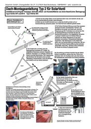
Series Pb – Installation –<br />
<strong>Automatic</strong> <strong>Charger</strong> Series Pb<br />
Designed for campers, boats, special purpose vehicles and industrial application<br />
Charging Options: 1 or 2 Supply batteries and<br />
1 or 2 Starter batteries<br />
Standard Equipment:<br />
• Charging programs No. 1, 2 and 4 (gel, AGM, acid) adjustable to the battery type (refer to page 7, Technical Data)<br />
• Outstanding charging technology (refer to page 5, Features)<br />
• The charging voltage is exempt from peaks, and it is controlled in such a way, that overcharging is excluded<br />
• All-automatic continuous operation for permanent readiness for use of the batteries<br />
• Precise temperature compensation of the battery (temperature sensor, order No. 2001, is required)<br />
• Separate auxiliary charging port “S” for support charging and conservation of charge of the vehicle’s starter battery, max. 2 A<br />
• <strong>Automatic</strong> battery regeneration in case of extended stop periods twice a week<br />
• Compensation of the voltage loss on the charging cables ensuring exact observation of the charging voltage rates<br />
• Intelligent microprocessor control observing the simultaneous supply of consumers<br />
• Separation of the batteries in case of power failure, overheating, incorrect behaviour (safety relay for each charging port)<br />
• Adjustable silent run function (reduction at night)<br />
• Power pack function allows continued operation of the consumers and preservation of data, such as in case of battery replacement<br />
Additional standard equipment for execution B:<br />
• Integrated charging current distributor with 2 main charging ports, each with max. current and output capacity<br />
• Charging current distributor can be switched to an own charging program for the starter battery<br />
• If required, the starter battery can also be charged with full charging current (short stop period of the vehicle)<br />
• Additional auxiliary charging port “S” for support charging and conservation of charge of a starter battery, max. 4 A<br />
• 4 Battery capacity rates can be adjusted (12 charging programs in total)<br />
• Inputs for sensor (sense) lines, which can be optionally used in case of charging cables in overlength and in case of external diode<br />
charging current distributors with voltage loss.<br />
• The mains/charging capacity can be reduced in case of low capacity or restricted power supply (power limit function)<br />
Additional standard equipment for execution C:<br />
• Further standard equipment identical with execution A and B (please observe the unit features)<br />
• 2 Main charging ports (A + B) with charging current distributor for 2 batteries of the same type with equal authorization<br />
Execution A<br />
Execution B
Charging Technology<br />
<strong>Automatic</strong> <strong>Charger</strong> Series Pb Trio<br />
3 Main charging ports, designed for boats, intervention vehicles and industrial application<br />
Charging Options: 2 Supply batteries and 1 starter battery or<br />
1 Supply battery and 2 starter batteries or<br />
3 Supply batteries or 3 starter batteries<br />
• Charging programs No. 1, 2 and 4 (gel, AGM, acid) adjustable to the battery type (refer to page 7, Technical Data)<br />
• Integrated charging current distributor with 3 main charging ports, each with max. current and output capacity for short charging times<br />
• For 1 or 2 starter batteries an own charging program can be adjusted at the integrated charging current distributor<br />
• Further standard equipment identical with execution A and B<br />
Unit Type Order No. Charging<br />
Capacity<br />
V/A<br />
Auxiliary<br />
Charging Port „S“<br />
A<br />
Battery<br />
Capacity<br />
Ah<br />
No. of<br />
Charging Ports<br />
Charging<br />
Current<br />
Distributor<br />
Dimensions *<br />
(DxWxH)<br />
mm<br />
Weight<br />
g<br />
Execution<br />
12 V<br />
Pb 1210 SMT 2B 3103 12/10 2 25–115 1+S – 205x160x71 1250 A<br />
Pb 1215 SMT 2B 3105 12/15 2 38–170 1+S – 205x160x71 1250 A<br />
Pb 1220 SMT 2B 3107 12/20 2 50–230 1+S – 205x160x71 1300 A<br />
Pb 1225 SMT 2B 3109 12/25 2 60–290 1+S – 205x160x71 1300 A<br />
Pb 1230 SMT 2B 3116 12/30 2 75–350 1+S – 205x160x71 1400 A<br />
Pb 1240 SMT 3B 3118 12/40 4 75–480 2+S Yes 305x160x71 2350 B<br />
Pb 1250 SMT 3B 3119 12/50 4 88–550 2+S Yes 305x160x71 2400 B<br />
Pb 1260 SMT 3B 3123 12/60 2 120–660 2+S Yes 305x263x88 3800 C<br />
Pb 1250 SMT Trio 3138 12/50 – 88-550 3 Yes 305x160x71 2500 D<br />
24 V<br />
Pb 2412 SMT 2B 6233 24/12 2 32–160 1+S – 205x160x71 1350 A<br />
Pb 2416 SMT 2B 6235 24/16 2 40-200 1+S – 205x160x71 1400 A<br />
Pb 2420 SMT 3B 6237 24/20 4 40–230 2+S Yes 305x160x71 2300 B<br />
Pb 2425 SMT 3B 6239 24/25 4 50–290 2+S Yes 305x160x71 2400 B<br />
Pb 2430 SMT 3B 6243 24/30 2 75–350 2+S Yes 305x263x88 3800 C<br />
* Dimensions incl. mounting flanges, without connections<br />
Delivery Scope:<br />
Mains cable, manual<br />
Recommendable Accessories: Temperature sensor, order No. 2001, remote control, order No. 3129<br />
Remote indicator, order No. 3127, remote distributor for chargers, order No. 2074<br />
Execution C<br />
Execution D<br />
Option:<br />
Remote control
<strong>VOTRONIC</strong> <strong>Automatic</strong> <strong>Charger</strong>s<br />
Series VAC – Installation –<br />
<strong>Automatic</strong> <strong>Charger</strong> Series VAC<br />
Adapted to intervention vehicles with strongly varying mission cycles.<br />
Charging Options: 2 Main charging ports for 1 Supply battery and 1 starter battery or<br />
2 Supply batteries or 2 starter batteries<br />
Standard Equipment:<br />
• Charging programs No. 1, 2, 3 and 5 (gel, AGM, acid, start) adjustable to the battery type (refer to page 7, Technical Data)<br />
• Outstanding charging technology (refer to page 5, Features)<br />
• The charging voltage is exempt from peaks, and it is controlled in such a way, that overcharging is excluded<br />
• Integrated charging current distributor with 2 main charging ports, each with max. current and output capacity<br />
• Charging current distributor can be switched to a 2 nd own charging program for the starter battery<br />
• If required, the starter battery can also be charged with full charging current (short stop period of the vehicle)<br />
• Additional auxiliary charging port “S” for support charging and conservation of charge of a starter battery (max. 2 A) or as signalling<br />
port +86 for motor locking while the vehicle is connected to mains<br />
• All-automatic continuous operation for permanent readiness for use of the vehicle<br />
• Precise battery temperature compensation, temperature sensor(s) is (are) included in the standard delivery<br />
• Equalization function (the characteristic line IUIU can be activated manually for compensation charging of the cells)<br />
• Intelligent microprocessor control observing the simultaneous supply of consumers<br />
• Battery regeneration in case of extended stop periods twice a week<br />
• Compensation of the voltage loss on the charging cables ensuring exact observation of the charging voltage rates<br />
• Separation of the batteries in case of power failure, overheating, incorrect behaviour (safety relay for each charging port)<br />
• Adjustable silent run function (reduction at night)<br />
• Power pack function allows continued operation of the consumers and preservation of data, such as in case of battery replacement<br />
• The electronic system is protected against humidity<br />
• Variable fitting position by additional unit label<br />
Additional standard equipment for execution B:<br />
• 4 Battery capacity rates can be adjusted (16 charging programs in total)<br />
• Inputs for sensor (sense) lines, which can be optionally used in case of charging cables in overlength and in case of external diode<br />
charging current distributors with voltage loss.<br />
• The mains/charging capacity can be reduced in case of low capacity or restricted power supply (power limit function)<br />
• Additional auxiliary charging port “S” for support charging and conservation of charge of a starter battery, max. 4 A<br />
Additional standard equipment for execution C:<br />
• Further standard equipment identical with execution A and B<br />
• 2 Main charging ports (A + B) with charging current distributor for 2 batteries of the same type with equal authorization<br />
• Signalling port +86 for motor locking while the vehicle is connected to mains<br />
• Voltage compensation for external diode charging current distributor can be adjusted (+0.63 V)<br />
Execution A<br />
Execution B<br />
10
Charging Technology<br />
<strong>Automatic</strong> <strong>Charger</strong> Series VAC Trio<br />
3 Main charging ports, designed for intervention vehicles, the marine field and industrial application:<br />
Charging Options: 2 Supply batteries and 1 starter battery or<br />
1 Supply battery and 2 starter batteries or<br />
3 Supply batteries or 3 starter batteries<br />
• Charging programs No. 1, 2, 3 and 5 (gel, AGM, acid, start) adjustable to the battery type (refer to page 7, Technical Data)<br />
• Integrated charging current distributor with 3 main charging ports, each with max. current and output capacity<br />
• For 1 or 2 starter batteries an own charging program can be adjusted at the integrated charging current distributor<br />
• Further standard equipment identical with execution A and B<br />
Unit Type Order No. Charging<br />
Capacity<br />
V/A<br />
Auxiliary<br />
Charging Port „S“<br />
A<br />
Battery<br />
Capacity<br />
Ah<br />
No. of<br />
Charging<br />
Ports<br />
Charging Current<br />
Distributor<br />
No. of<br />
Temp. Sensors<br />
Dimensions *<br />
(WxDxH)<br />
mm<br />
Weight<br />
g<br />
Execution<br />
12 V<br />
VAC 1210 M 3A 0412 12/10 2 25–115 2+S Yes 1 205x160x71 1250 A<br />
VAC 1215 M 3A 0414 12/15 2 38–170 2+S Yes 1 205x160x71 1280 A<br />
VAC 1220 M 3A 0416 12/20 2 50–230 2+S Yes 1 205x160x71 1300 A<br />
VAC 1225 M 3A 0418 12/25 2 60–290 2+S Yes 1 205x160x71 1350 A<br />
VAC 1230 M 3A 0422 12/30 2 75–350 2+S Yes 1 205x160x71 1450 A<br />
VAC 1240 M 3A 0424 12/40 4 75–480 2+S Yes 2 305x160x71 2400 B<br />
VAC 1250 M 3A 0426 12/50 4 88–550 2+S Yes 2 305x160x71 2450 B<br />
VAC 1260 M 3A 0431 12/60 2 120–660 2+S Yes 2 330x265x90 3900 C<br />
VAC 1250 M Trio 0428 12/50 – 88–550 3 Yes 3 305x160x71 2600 D<br />
24 V<br />
VAC 2412 M 3A 0448 24/12 2 32–160 2+S Yes 1 205x160x71 1350 A<br />
VAC 2416 M 3A 0449 24/16 2 40–200 2+S Yes 1 205x160x71 1450 A<br />
VAC 2420 M 3A 0458 24/20 4 40–230 2+S Yes 2 305x160x71 2350 B<br />
VAC 2425 M 3A 0459 24/25 4 46–290 2+S Yes 2 305x160x71 2400 B<br />
VAC 2430 M 3A 0460 24/30 2 75–350 2+S Yes 2 330x265x90 3900 C<br />
* Dimensions incl. mounting flanges, without connections<br />
Delivery Scope: Mains cable, manual, 2 nd unit label, self-adhesive (execution A, B and D)<br />
Temperature sensor(s): 1 Pc. execution A, 2 pcs. execution B+C, 3 pcs. execution D<br />
Recommendable Accessories: Remote control, order No. 3129, remote indicator, order No. 3127<br />
Remote distributor for chargers, order No. 2074<br />
Execution C<br />
Execution D<br />
Option:<br />
Remote control<br />
11
<strong>VOTRONIC</strong> <strong>Automatic</strong> <strong>Charger</strong>s<br />
Series VAC – Installation –<br />
Execution A<br />
Execution B<br />
<strong>Automatic</strong> <strong>Charger</strong> Series VAC-F DIN 14679<br />
Built-in chargers for fire fighting vehicles and intervention vehicles.<br />
2 Main charging ports with charging current distributor for: 1 Supply battery or 1 starter battery or<br />
1 Supply battery and 1 starter battery or<br />
2 Supply batteries or 2 starter batteries<br />
The charger series VAC-F is designed for installation in the vehicle and complies with all regulations of the FNFW of the valid<br />
fire brigade standard DIN 14679 for charging and conservation of charge of auxiliary batteries and starter batteries in intervention<br />
vehicles.<br />
• Charging programs No. 5, 6, 7, 8 and 9 (start, gel, AGM, acid) adjustable (refer to page 7, Technical Data)<br />
• Outstanding charging technology (refer to page 5, Features)<br />
• All-automatic continuous operation for permanent readiness for use of the vehicle<br />
• The charging voltage is exempt from peaks, and it is controlled in such a way, that overcharging is excluded<br />
• Trouble-free operation and simultaneous supply of the units being connected to the vehicle’s board mains supply<br />
• Integrated charging current distributor with 2 main charging ports, each with max. current and output capacity<br />
• Charging current distributor output “2”, can be switched to an own charging program for the starter battery<br />
• If required, the starter battery can also be charged with full charging current (short stop period of the vehicle)<br />
• Additional 3 rd auxiliary charging port “S” for support charging and conservation of charge of a starter battery<br />
(max. 2 A or 4 A execution B)<br />
• Optical and acoustical warning in case of battery failures and operating errors<br />
• Precise temperature compensation, temperature sensor(s) is (are) included in the standard delivery<br />
• Battery regeneration in case of extended stop periods twice a week<br />
• Compensation of the voltage loss on the charging cables ensuring exact observation of the charging voltage rates<br />
• Separation of the batteries in case of power failure, overheating, incorrect behaviour (safety relay for each charging port)<br />
• Power pack function allows continued operation of the consumers and preservation of data, such as in case of battery replacement<br />
• Manual charging start for totally discharged battery according to DIN 14679<br />
• Variable fitting position by additional unit label<br />
• The electronic system is protected against humidity<br />
Unit Type<br />
Order<br />
No.<br />
Charging<br />
Capacity<br />
V/A<br />
Battery<br />
Capacity<br />
Ah<br />
No. of<br />
Charg.<br />
Ports<br />
Charg.<br />
Curr.<br />
Distrib.<br />
No. of<br />
Temp.<br />
Sensors<br />
Dimensions**<br />
(WxDxH)<br />
mm<br />
Weight Execution<br />
g<br />
12 V<br />
VAC 1215 F3A 0472 12/15 30-75 (150*) 2+S Yes 1 205x160x71 1350 A<br />
VAC 1230 F3A 0478 12/30 50-150 (300*) 2+S Yes 1 205x160x71 1450 A<br />
VAC 1250 F3A 0482 12/50 85-250 (500*) 2+S Yes 2 305x160x71 2450 B<br />
24 V<br />
VAC 2416 F3A 0492 24/16 30-80 (160*) 2+S Yes 1 205x160x71 1450 A<br />
VAC 2425 F3A 0496 24/25 40-125 (250*) 2+S Yes 2 305x160x71 2400 B<br />
*in case of stop periods of the vehicles >24 hours, acc. to DIN 14679<br />
**Dimensions incl. mounting flanges, without connections<br />
Delivery Scope:<br />
Temperature sensor(s), mains cable, manual, 2 nd unit label self-adhesive<br />
Recommendable Accessories: Remote control, order No. 3129, remote indicator, order No. 3127<br />
<strong>Automatic</strong> <strong>Charger</strong> Series VAC-F II DIN 14679<br />
Built-in chargers in protection class II for fire fighting vehicles and intervention vehicles.<br />
2 Main charging ports with charging current distributor for: 1 Supply battery or 1 starter battery or<br />
1 Supply battery and 1 starter battery or<br />
2 Supply batteries or 2 starter batteries<br />
The charger series VAC-F II is designed for installation in the vehicle and complies with all regulations of the FNFW of the<br />
valid fire brigade standard DIN 14679 for charging and following conservation of charge of auxiliary batteries and starter<br />
batteries in intervention vehicles. The units of this series are equipped with a protective insulation (protection class II, without<br />
connection of a protective conductor). According to DIN 14679 they can be used for a (mains) single installation in<br />
the vehicle without connection of a protective conductor. The technical equipment, features and advantages, as well as the<br />
charging possibilities are identical with the charger series VAC-F (see above).<br />
12<br />
Unit Type<br />
Order<br />
No.<br />
Charging<br />
Capacity<br />
V/A<br />
Battery<br />
Capacity<br />
Ah<br />
No. of<br />
Charg.<br />
Ports<br />
Charg.<br />
Curr.<br />
Distrib.<br />
No. of<br />
Temp.<br />
Sensors<br />
Dimensions**<br />
(WxDxH)<br />
mm<br />
Weight Execution<br />
g<br />
12 V<br />
VAC 1215 F3A II 0473 12/15 30-75 (150*) 2+S Yes 1 205x160x71 1350 A<br />
VAC 1230 F3A II 0479 12/30 50-150 (300*) 2+S Yes 1 205x160x71 1450 A<br />
24 V<br />
VAC 2416 F3A II 0493 24/16 30-80 (160*) 2+S Yes 1 205x160x71 1450 A<br />
*in case of stop periods of the vehicles >24 hours, acc. to DIN 14679<br />
**Dimensions incl. mounting flanges, without connections<br />
Delivery Scope:<br />
Temperature sensor, mains cable, 2-core, manual, 2 nd unit label self-adhesive<br />
Recommendable Accessories: Remote control, order No. 3129, remote indicator No. 3127
<strong>VOTRONIC</strong> <strong>Automatic</strong> <strong>Charger</strong><br />
Series VAC – Stationary Application –<br />
Charging Technology<br />
<strong>Automatic</strong> <strong>Charger</strong> VAC-Station<br />
<strong>Charger</strong>s for external charging for intervention vehicles in vehicle halls<br />
with permanent or variable parking lots<br />
Charging Options: Vehicle battery + additional consumers<br />
The charger series VAC-Station is suitable for application in vehicle halls and complies with all regulations of the FNFW of<br />
the valid fire brigade standard DIN 14679 for external charging and following conservation of charge of starter and auxiliary<br />
batteries in fire fighting vehicles with the exception of the protection against splash water IP21.<br />
• Charging programs No. 5, 6, 7, 8, 9 and 10 adjustable for all battery types (refer to page 7, General Technical Data)<br />
• VAC 1224-16 Station with automatic recognition and commutation to 12 V / 24 V board supply voltage<br />
• <strong>Automatic</strong> separation from mains of the charging connector in case of missing battery (to prevent short-circuit and<br />
corrosion of connector)<br />
• Optical and acoustical warning in case of battery failures and connection errors<br />
• Outstanding charging technology (refer to page 5, Features)<br />
• Trouble-free operation and simultaneous supply of the units being connected to the vehicle’s board mains supply<br />
• All-automatic continuous operation for permanent readiness for use of the vehicle<br />
• Compensation of the voltage loss on the charging cables ensuring exact observation of the charging voltage rates<br />
• Variable fitting position due to additional unit label (included in the standard delivery)<br />
• The electronic system is protected against humidity<br />
• Cable Ölflex (4 m length) or helix cable (max. length 5 m), each with C-connector DIN 14690, included in the standard<br />
delivery.<br />
Unit Type<br />
With Cable<br />
Ölflex<br />
4 m Length<br />
Order No.<br />
With Helix<br />
Cable<br />
5 m Length<br />
Order No.<br />
Charging<br />
Capacity<br />
Battery<br />
Capacity<br />
Dimensions *<br />
(WxDxH)<br />
Weight<br />
without<br />
Cable<br />
g<br />
Ah<br />
mm<br />
12 V<br />
VAC 1210 Station 0572 0562 12V/10A 40-160 205x160x71 1250<br />
VAC 1215 Station – 0564 12V/15A 60-160 205x160x71 1250<br />
VAC 1220 Station** 0574 – 12V/20A 80-230 205x160x71 1300<br />
12 V <strong>und</strong> 24 V<br />
VAC 1224-16 Station 0570 0560 12V/24V/16A 70-160 205x160x71 1400<br />
24 V<br />
VAC 2412 Station 0576 0566 24V/12A 50-160 205x160x71 1350<br />
VAC 2416 Station 0579 0569 24V/16A 70-160 205x160x71 1400<br />
* Dimensions incl. mounting flanges, without connections ** Unit with 20 A charging current above the regulations of DIN 14679<br />
Delivery Scope:<br />
Mains cable, second unit label, manual, cable „Ölflex“ or helix cable, C-connector<br />
Recommendable Accessories: Remote control, order No. 3129, remote indicator, order No. 3127<br />
<strong>Automatic</strong> <strong>Charger</strong> VAC-Station for 12 V + 24 V - Board Mains Supply<br />
Waterproof and dustproof chargers (IP 65) for external battery charging for fire fighting vehicles<br />
in vehicle halls with universal parking lots<br />
Charging Options: Vehicle battery + additional consumers<br />
• <strong>Automatic</strong> recognition and commutation to 12 V / 24 V board supply voltage.<br />
• External charging and conservation of charge of the vehicle’s battery (charging program No. 5)<br />
• Trouble-free operation and simultaneous supply of the units being connected to the vehicle’s board mains supply<br />
• All-automatic continuous operation for permanent readiness for use of the vehicle<br />
• <strong>Automatic</strong> separation from mains of the charging connector in case of missing battery (to prevent short-circuit and<br />
corrosion of connector)<br />
• Compensation of voltage loss on the charging cables up to a length of 22 m<br />
• With cable “Ölflex” of 2 m length for further connection of C-connector DIN 14690, cable rewinder or helix cable via<br />
connecting box, order No. 2310 (see Accessories)<br />
Unit Type<br />
Execution<br />
with Cable<br />
Ölflex, 2 m Length<br />
Order No.<br />
Charging<br />
Capacity<br />
Battery<br />
Capacity<br />
Ah<br />
Dimensions *<br />
(WxDxH)<br />
mm<br />
Weight:<br />
without<br />
Cable<br />
g<br />
VAC 12/24-05 Station 0594 12V/24V/5A 40-140 300x230x130 5700<br />
VAC 12/24-08 Station 0598 12V/24V/8A 50-180 300x230x130 5800<br />
VAC 12/24-12 Station 0599 12V/24V/12A 70-200 300x230x130 5900<br />
* Dimensions incl. mounting flanges, without connections<br />
Delivery Scope:<br />
Manual, cable Ölflex, 2 m<br />
Recommendable Accessories: <strong>Automatic</strong> cable rewinder, order No. 2312 or order No. 2314 (not 12 A)<br />
Optionally: Helix cable, order No. 2318, Connecting box, order No. 2310 for autom.<br />
cable rewinder and helix cable, charging connector for Fire fighting vehicles<br />
acc. to DIN 14690 (C-connector), order No. 2323 or MagCode Power System<br />
12V + 24V<br />
13
<strong>VOTRONIC</strong> <strong>Automatic</strong> <strong>Charger</strong>s<br />
Series VAC – Installation –<br />
<strong>Automatic</strong> <strong>Charger</strong> VAC - Duo<br />
Dual <strong>Charger</strong> for intervention vehicles with 2 independent battery circuits<br />
Charging Options:<br />
1 Supply battery and 1 starter battery or<br />
2 Supply batteries or 2 starter batteries<br />
Standard Equipment:<br />
• 2 Completely individual and independent charging parts in one unit<br />
• Charging programs No. 1, 2, 3 and 5 adjustable per charging part (refer to page 7, Technical Data)<br />
• 4 Battery capacity rates per charging part can be adjusted (16 charging programs in total)<br />
• Charging and conservation of charge of the starter battery are adjustable according to the tentative standards of the<br />
Committee Fire Protection (FNFW)<br />
• Outstanding charging technology (refer to page 5, Features)<br />
• Port +86 for motor locking while the vehicle is connected to mains<br />
• <strong>Automatic</strong> battery regeneration in case of extended stop periods<br />
• Compensation of the voltage loss on the charging cables ensuring exact observation of the charging voltage rates<br />
• Inputs for sensor lines, which can optionally be used in case of charging cables in overlength (execution without start<br />
bridge)<br />
• Separation of the batteries in case of power failure, overheating, incorrect behaviour (safety relay for each charging<br />
port)<br />
• The electronic system is protected against humidity<br />
VAC-Duo Dual <strong>Charger</strong> with Integrated Start Bridge:<br />
• Integrated battery bridge function 200 A for emergency start of the motor, can also be remote-controlled by push-button<br />
• An emergency start of the motor is also possible by means of a simple push-button, e. g. from the dashboard<br />
• Other capacity combinations or 24 V units upon request<br />
With 2<br />
independent<br />
charging parts<br />
VAC-Duo Dual <strong>Charger</strong>, Execution without Integrated Start Bridge:<br />
• Inputs for sensor lines, which can be optionally used in case of charging cables in overlength or in case of external diode<br />
charging current distributors with voltage loss.<br />
• Other capacity combinations or 24 V units upon request<br />
Unit Type Order No.<br />
with<br />
Start Bridge<br />
Function<br />
Order No.<br />
without<br />
Start Bridge<br />
Function<br />
Charging<br />
Capacity<br />
Battery<br />
Capacity<br />
No. of<br />
Temp.<br />
Sensors<br />
Output<br />
Motor<br />
Locking<br />
12V/0,4A<br />
Dimensions* Weight<br />
(DxWxH)<br />
V/A/A Ah<br />
mm g<br />
VAC 1215/15 Duo 0625 0626 12/15/15 36–170/36–170 2 Yes 305x265x90 3700<br />
VAC 1215/30 Duo 0628 0627 12/15/30 36–170/75–350 2 Yes 305x265x90 3700<br />
VAC 1220/20 Duo 0630 0629 12/20/20 50–230/50–230 2 Yes 305x265x90 3700<br />
VAC 1220/30 Duo 0632 0631 12/20/30 50–230/75–350 2 Yes 305x265x90 3750<br />
VAC 1220/40 Duo 0633 0634 12/20/40 50–230/90–480 2 Yes 305x265x90 3900<br />
* Dimensions incl. mounting flanges, without connections<br />
Delivery Scope:<br />
2 Temperature sensors, mains cable, manual<br />
Recommendable Accessories: Remote display for VAC Duo, order No. 0699<br />
Remote indicator, order No. 3127<br />
Remote Indicator for <strong>Automatic</strong> <strong>Charger</strong> VAC-Duo, Order No. 0699<br />
For control of the 2 separate battery circuits of the chargers VAC-Duo. The pilot lamps (LED) are indicating the corresponding<br />
charging progress. The remote control is delivered as panel version in black design matching to the <strong>VOTRONIC</strong> modular<br />
system. Dim. (WxHxD): 47x85x16 mm.<br />
Delivery Scope: Connection cable, 5 m length, fastening screws, drilling jig.<br />
14
Batteries<br />
<strong>VOTRONIC</strong> Board Supply Batteries<br />
The following supply batteries are designed for cyclic load ensuring charging/discharging with supply of the consumers over<br />
a longer period, also with higher current rates and down to lower discharge. In contrast to conventional starter batteries,<br />
they are particularly suitable as consumer/board battery or as solar battery.<br />
Distinction must be made between batteries with fixed electrolyte in gel or AGM execution and the classical liquid/acid<br />
batteries. Gel and AGM batteries are leak-proof and absolutely maintenance-free over the complete lifetime. At the required<br />
charging conditions high cycle stability is achieved by both battery types. Gel batteries allow short-time very deep discharge,<br />
on condition that they will be recharged immediately. AGM batteries with the same dimensions have a slightly higher<br />
capacity and allow a short-time operation with very high charging/discharging current rates.<br />
The automatic <strong>VOTRONIC</strong> battery chargers and solar controllers are offering the suitable charging programs and characteristic<br />
lines of charging for high efficiency and longevity of the batteries.<br />
Execution A<br />
Acid Batteries<br />
Supply batteries in liquid acid execution with high efficiency and cycle stability for long-time consumers, inverter application<br />
and solar operation, mobile and stationary. The batteries distinguish by low self-discharge and low maintenance<br />
and they allow level control and central degassing to outside with a good price-performance payoff at the same time.<br />
The delivery within Germany is effected ready for use, freight prepaid, including acid filling.<br />
AGM Batteries<br />
These batteries are leak-proof, orientation-independent and absolutely maintenance-free board batteries according to the<br />
latest AGM technology, which means that the electrolyte is completely fixed in the glass fibre fleece. They had been developed<br />
for a very high cycle load for all applications, such as for long-time consumers, inverter application with high current<br />
rates and solar operation, mobile and stationary. On principle, these batteries are released for interiors, since an outlet to<br />
outside is not required. Another advantage compared with gel batteries is the higher storage capacity with the same space<br />
requirements. Due to the high current delivery they are also suitable for motor start. Furthermore, they distinguish by a very<br />
good charging current acceptance, even at cool temperatures, which might become apparent in shorter charging times or a<br />
higher charging state after short driving times.<br />
Execution B<br />
Gel Batteries<br />
Leak-proof, orientation-independent and absolutely maintenance-free board batteries in the proven gel technology, which<br />
means that the electrolyte is not liquid but fixed in gel. Developed for the daily consumers on board. Gel batteries distinguish<br />
by very high cycle loads with reserve capacity, such as in case of long-time consumers, inverter application and solar operation,<br />
mobile and stationary. On principle, these batteries are released for interiors, since an outlet to outside is not required.<br />
Gel batteries are very longevous, and they are very robust towards total discharge if charging is optimally adapted.<br />
Execution C<br />
12 Volts Order No. Nominal<br />
Voltage<br />
Capacity<br />
100h<br />
Dimensions<br />
(WxLxH)<br />
mm<br />
Weight<br />
approx.<br />
Execution<br />
Acid Board Battery 90 Ah (100h) 2385 12 V 90 Ah 247x175x190 mm 20 kg A<br />
Acid Board Battery 125 Ah (100h) 2386 12 V 125 Ah 353x175x190 mm 25 kg A<br />
AGM Board Battery 90 Ah (100h) 2388 12 V 90 Ah 287x175x190 mm 19 kg B<br />
AGM Board Battery 120 Ah (100h) 2390 12 V 120 Ah 332x174x213 mm 32 kg C<br />
AGM Board Battery 170 Ah (100h) 2391 12 V 170 Ah 482x170x242 mm 44 kg C<br />
Gel Board Battery 67 Ah (100h) 2393 12 V 67 Ah 278x175x190 mm 21 kg D<br />
Gel Board Battery 90 Ah (100h) 2394 12 V 90 Ah 353x175x190 mm 27 kg D<br />
Gel Board Battery 130 Ah (100h) 2396 12 V 130 Ah 513x189x223 mm 41 kg D<br />
Gel Board Battery 155 Ah (100h) 2397 12 V 155 Ah 513x223x225 mm 48 kg D<br />
Gel Board Battery 235 Ah (100h) 2398 12 V 235 Ah 518x291x242 mm 70 kg D<br />
Execution D<br />
15
<strong>VOTRONIC</strong> Sine Inverters<br />
Perfect Supply Voltage During Driving<br />
<strong>VOTRONIC</strong> Sine Inverters<br />
230 Volts alternating voltage like out of the socket<br />
When being on the road with a vehicle, nobody wants to renounce comforts. Electronic<br />
equipment not only improves the comfort in the leisure vehicle, but is also decisive for the<br />
equipment in ambulance cars or fire fighting vehicles. These electronic appliances might<br />
be sensitive medical equipment, computers, video and TV systems, electrical tools or the<br />
preferred espresso machine. Since, however, all units require 230 V supply voltage, use in<br />
a vehicle requires transformation of the direct current (DC) of the battery to alternating<br />
current (AC). The inverter takes over this task. It supplies a steady, crystal exact, sinusoidal<br />
alternating current of 230 V / 50 Hz, which is suitable for 230 V consumers.<br />
The size of the inverter is determined by the case of application. So, a coffee machine<br />
requires a more powerful unit than a razor. More powerful inverters require more current<br />
and consequently larger batteries. Usually, this fact is not considered when purchasing an<br />
inverter.<br />
Consequently, the current requirement is not determined by the size of the inverter, but by<br />
the size of the connected consumer. The following rough formula is applied: Capacity of the<br />
230 V consumer divided by 10 results in the approximate current value being taken from<br />
the battery. Dimensioning of the adequate battery size (Ah) can be based on the example<br />
for calculation on page 4.<br />
For your guidance, we recommend a battery capacity of about 100 Ah at 250 W (VA), while<br />
at least 200 Ah should be at disposal from 1000-1500 W (Ah).<br />
The case of application does also determine, if a sine inverter is required, or if a significantly<br />
more economic unit being similar to a sine inverter can be applied. An incandescent lamp<br />
or a hair drier does not have high requirements regarding the inverter, while units with a<br />
particular start behaviour, such as air conditioners, drills, vacuum cleaners or appliances<br />
being equipped with a sensitive electronic control (e. g. coffee makers, computers, medical<br />
equipment) possibly might require a sine inverter. Very often, this problem is neither<br />
recognizable, nor can it be drawn from the operating manual of the corresponding 230 V<br />
appliance!<br />
Further, it can not be concluded from the appearance of a designer fan that it might require<br />
230 V sine. To avoid making compromises or convincing the specialised dealer to take an<br />
appliance back, a high-quality sine inverter is always the better choice! These units supply<br />
a sinusoidal 230 V supply voltage, as if it came out of the socket, and thus they are suitable<br />
for all 230 V appliances.<br />
The precious battery capacity being only available within limits should not be wasted for<br />
the 230 V consumers, if 230 V mains voltage is at disposal via the country current connection<br />
at the vehicle. With the <strong>VOTRONIC</strong> Sine Inverters of type -NVS with automatic mains<br />
priority control, continual changing from the mains socket at the inverter (driving mode)<br />
to the internal 230 V vehicle socket (standstill with mains supply) is avoided. The mains<br />
priority control recognizes if 230 V country current is available and disconnects the inverter,<br />
so that the 230 V appliances at the internal vehicle sockets will be supplied with country<br />
current, and the battery is not discharged unnecessarily. As soon as the vehicle is separated<br />
from the country current, the inverter automatically (adjustable) resumes the supply of the<br />
230 V appliances.<br />
This intelligent device ensures, that 230 V alternating voltage will always be supplied to<br />
the sockets in the vehicle.<br />
Very often, the power consumption (Watts) is indicated in VA and can be drawn from the technical data or the nameplate of the 230 V consumer.<br />
Following some examples:<br />
Razor 10 VA DVD Player 30 VA Incandescent Lamp 25-100 W<br />
Coffee Maker 1200 VA Sat Receiver 20 VA Storage Battery <strong>Charger</strong> 50 VA<br />
Power Pack Laptop 75-140 VA Hair Drier 1000-1500 VA Mobile Phone <strong>Charger</strong> 30 VA<br />
TV 80 VA Drill 400-800 VA Vacuum Cleaner 1000-1500 VA<br />
Please observe, that the indicated values are always nominal values. The momentary power consumption might be three or five times higher than the indicated<br />
value due to e. g. starting current.<br />
For air-conditioners mostly the generated cooling capacity is indicated, but the required electrical capacity is lower. The choice of a suitable inverter must be<br />
based on the increased starting current. We recommend the following inverter for operation of air-conditioners:<br />
- Air-conditioners up to 1700 W cooling capacity: MobilPOWER Inverter SMI 1000 (-NVS) Sinus<br />
- Air-conditioners up to 2300 W cooling capacity: MobilPOWER Inverter SMI 1500 (-NVS) Sinus<br />
General Technical Data Sine Inverter<br />
Input Voltage (DC): 12V (10.5V - 15V) / 24V (21V - 30V)<br />
Output Voltage (AC):<br />
230 V pure sine<br />
Output Frequency:<br />
50 Hz, crystal stabilized<br />
Efficiency: > 93%<br />
CosPhi of the Consumers:<br />
≤ 1, no restriction<br />
Overvoltage Battery max.:<br />
16.0 V / 32.0 V<br />
Low Voltage Battery min.:<br />
10.5 V / 21.0 V (load-dependent, dynam.)<br />
Overload Protection:<br />
Yes<br />
Overtemperature Protection:<br />
Yes<br />
Fan with Continuous Temp. Control: Yes<br />
Power-saving Mode:<br />
Yes<br />
Remote Control:<br />
Yes<br />
Autom. Commutation to Mains (only –“NVS“): Rating max. 2300 W<br />
Input Country Current 230 V/AC (only –“NVS“): Socket for Cold Appliances<br />
System of Protection / Protection classes: IP21 / I, II<br />
Temperature range: -20 to +45 °C<br />
Ambient Conditions, Humidity of Air:<br />
max. 95% RH, no condensation<br />
Safety Regulations: EN 60950<br />
Mark of Conformity: CE, E Test acc. to ECE R10 Rev. 2<br />
(EMV/Automotive Regulations)<br />
16<br />
Recommendable Accessories: Control unit, order No. 2065, ON/OFF control unit for sine inverter, see page 41<br />
Additional remote control for sine inverter, order No. 2067, extension set with 2 nd remote control, see page 41
Voltage Transformers<br />
<strong>VOTRONIC</strong> MobilPOWER Inverter<br />
Sine Inverter for Mobile Use<br />
The <strong>VOTRONIC</strong> MobilPOWER Inverters of series SMI SINUS convert the battery voltage (12 V DC) into pure sinusoidal 230 V<br />
alternating voltage (AC) for operation of all appliances requiring mains supply.<br />
They are designed in advanced switch mode technology for continuous operation in intervention vehicles and special purpose<br />
vehicles, high-quality campers and in the marine field. They are of compact lightweight design, and they distinguish by<br />
high output capacity and low consumption at the same time.<br />
An intelligent control for power saving with automatic disconnection allows uninterrupted operation of powerful 230 V<br />
consumers, as well as of small, sensitive appliances with minimum battery consumption. Numerous integrated protective circuits,<br />
robust power electronics and intelligent microprocessor control ensure a very high overload capacity (starting current<br />
of consumers) and high operating safety, even in case of unfavourable operating conditions, in the long run.<br />
Depending on the fitting position, the removable control panel can be installed conveniently, or it can even be used as<br />
complete remote control in the cabin (connection cable of a length of 5 m is provided).<br />
Six light-emitting diodes indicate the operating state, as well as the instantaneous values of the range of capacity. Of course,<br />
the unit can also be switched-on and off by means of the remote control.<br />
A special feature of the series -NVS is the integrated mains priority control. As soon as country current is supplied to the<br />
vehicle, the mains priority control ensures automatic supply of country current to the mains sockets in the vehicle, as well<br />
as complete disconnection of the inverter in order to stop the power discharge from the battery. If the vehicle is separated<br />
from the external current, the inverter automatically resumes the supply of the 230 V consumers.<br />
• Output voltage in quality of mains voltage (pure sine)<br />
• Uncompromising, unproblematic, trouble-free operation of all the mains operated appliances, such as medical equipment,<br />
radio equipment, charging devices (of mobile phones, wireless transmitting sets, hand lamps, storage batteries<br />
etc.), laptops, computers, air-conditioners, refrigerator boxes, electric tools (drills, right angle grinders etc.), TV, SAT, TFT,<br />
microwave ovens, fully automatic coffee makers, hair driers, fans, lamps, vacuum cleaners, refrigerators etc.<br />
• The control panel can be rotated by 360 °, and it can be used as remote control (e. g. in the cabin).<br />
• Switch mode technology, compact, lightweight, robust and reliable, short-time high overload is admissible<br />
• Low current consumption, selectable power-saving mode: Continuous operation, automatic stand-by with automatic<br />
search for switched-on consumers, OFF<br />
• <strong>Automatic</strong> disconnection in case of overvoltage/low voltage of the battery, overload, overheating etc.<br />
• Comfort cooling fan with power control, temperature control and continuous speed control<br />
• Integrated mains priority control with overload protection 10 A safety cutout (only series -NVS)<br />
• Ready for connection, with cables<br />
• Suitable for air-conditioners<br />
• Mains priority control integrated<br />
Execution A<br />
Execution B<br />
Execution C<br />
Unit Type Order Output Capacity Own Connection Cable Dimensions * Weight Execution<br />
MobilPOWER No. Permanent/ Consumption Battery ** (WxDxH)<br />
Inverter … Sinus Short-time/Peak Off/Stand-by/ Length/Cross Section/<br />
W Mains approx. W Cable Lug mm g<br />
SMI 300 3155 300/420/600 0 / 3 / - 2x1m/ 4mm²/ M8 160x205x71 1300 A<br />
SMI 300-NVS 3156 300/420/600 0 / 3 / 0 2x1m/ 4mm²/ M8 160x305x71 1800 B<br />
SMI 300 / 24V 6155 300/420/600 0 / 3 / - 2x1m/ 4mm²/ M8 160x205x71 1300 B<br />
SMI 300-NVS / 24V 6156 300/420/600 0 / 3 / 0 2x1m/ 4mm²/ M8 160x305x71 1800 B<br />
SMI 600 3157 600/840/1200 0 / 5 / - 2x1m/ 10mm²/ M8 160x305x71 2200 B<br />
SMI 600-NVS 3158 600/840/1200 0 / 5 / 0 2x1m/ 10mm²/ M8 160x305x71 2500 B<br />
SMI 600 / 24V 6157 600/840/1200 0 / 5 / - 2x1m/ 10mm²/ M8 160x305x71 2200 B<br />
SMI 600-NVS / 24V 6158 600/840/1200 0 / 5 / 0 2x1m/ 10mm²/ M8 160x305x71 2500 B<br />
SMI 1000 3163 1000/1400/2000 0 / 8 / - 2x1.4m/ 25 mm²/ M8 265x305x90 4900 C<br />
SMI 1000-NVS 3164 1000/1400/2000 0 / 8 / 0 2x1.4m/ 25 mm²/ M8 265x305x90 5100 C<br />
SMI 1500 3165 1500/2100/3000 0 / 10 / - 2x1.4m/ 35 mm²/ M8 265x425x90 5900 D<br />
SMI 1500-NVS 3166 1500/2100/3000 0 / 10 / 0 2x1.4m/ 35 mm²/ M8 265x425x90 6100 D<br />
* Dimensions incl. mounting flanges, without connections ** Cable included in the delivery, already installed at the unit<br />
Mark of Conformity: CE, E Test acc. to ECE R10 Rev. 2 (EMV/Automotive Regulations)<br />
Delivery Scope:<br />
Battery connection cable of a suitable cross-section, connection cable, 5 m length for<br />
control panel/remote control, mains cable (only -“NVS“), operating manual<br />
Recommended Accessories for SMI 300 and SMI 600 (protective covering of cables): Fuse Holder, order No. 2242<br />
Stripe fuse, 50 A, order No. 2245 (SMI 300), stripe fuse 80 A, order No. 2247 (SMI 600)<br />
Recommended Accessories for SMI 1000 and SMI 1500 (protective covering of cables):<br />
Power fuse holder, order No. 2250, Power fuse 175 A, order No. 2256 (for SMI 1000)<br />
Power fuse 225 A, order No. 2258 (for SMI 1500)<br />
High-current battery cable 25 mm², length 40 cm, order No. 2262 (for SMI 1000)<br />
High-current battery cable 35 mm², length 40 cm, order No. 2263 (for SMI 1500)<br />
Execution D<br />
Control panel of the<br />
inverter shown above ,<br />
at the unit (rotatable by<br />
90 °, depending on the<br />
mounting position) or for<br />
external use as remote<br />
control<br />
17
<strong>VOTRONIC</strong> Solar Current Technology<br />
Free Energy<br />
Spending the “most beautiful days of the year” in a camper is bo<strong>und</strong> up with the thought of<br />
freedom and independence. Away from the everyday routine, away from the narrowness of<br />
the city and the rules controlling the day. Leaving the worn-out paths, finding new parking<br />
lots and staying, where it is the most beautiful.<br />
When finally having fo<strong>und</strong> a “dream place”, nobody wants to leave already after 2 - 3 days<br />
in order to find a mains supply. The decision to resolve the problem by a running motor or<br />
petrol generator is resulting in trouble with the neighbours, and it is also insufficient for<br />
effective battery charging, since the duration is insufficient. However, use of the comfortable<br />
equipment of the vehicle is depending on the charging state of the board battery<br />
(batteries).<br />
The ideal resolution is the application of a solar current system or photovoltaic system,<br />
which, when being dimensioned correctly, does not only ensure the power supply of a<br />
camper or boat, but can be used at any place, where a power supply is missing. Nowadays,<br />
photovoltaic systems are widespread, and they are used for all kinds of application up to<br />
large network systems.<br />
The functional principle is always the same. In a solar cell, sunlight will be transformed into<br />
electric energy by means of the photovoltaic effect. Utilization of the energy is achieved by<br />
combining several solar cells to one solar module. More powerful systems can be realised<br />
by combination of several solar modules.<br />
This applies also to mobile application. The recovered energy will be stored in batteries to<br />
be available for operation of the electrical appliances during the night or in sunless times. A<br />
mobile solar system consists of three components: Solar module, solar charging controller<br />
and battery.<br />
The solar charging controller is the link between solar panel and battery preventing battery<br />
overload. To be able to store as much precious solar power as possible, the own consumption<br />
of the charging controller must be kept as low as possible. Furthermore, a modern<br />
solar charging controller should consider the different battery types during charging, and it<br />
should allow temperature compensated charging.<br />
<strong>VOTRONIC</strong> solar controllers meet these requirements and ensure effective battery charging.<br />
Apart from the second charging port, the control of Electrolux or Dometic refrigerators<br />
with AES function is possible. Optimum energy yield is achieved by two different control<br />
methods: The conventional shunt controller technology and the maximum power point<br />
(MPP) control method.<br />
Dimensioning of a solar system mainly depends on the energy consumption and the surface<br />
of the solar module. Consequently, it is particularly important to develop an energy balance<br />
in order to determine the total capacity of the connected consumers and thus the total<br />
requirement of energy per day in watt-hours (Wh). 30 % of this value must be added to<br />
cover battery loss and system loss. The result is the total capacity in Wh, which the solar<br />
modules should have at least. The solar charging controller is then chosen according to the<br />
capacity of the solar module. It is advisable to choose a controller of the next size up to be<br />
able to adding solar modules later, without having to replace the existing solar controller<br />
and the connection cables.<br />
Recommendation<br />
<strong>VOTRONIC</strong> Temperature Sensor, Order No. 2001<br />
Temperature sensor with connection cable of 2 m<br />
length and mounting hole M8. Sealed for protection<br />
against environmental pollution. Suitable for all<br />
<strong>VOTRONIC</strong> units and solar controllers.<br />
The Specialists for Professional Solar Charging Technology<br />
The <strong>VOTRONIC</strong> solar controllers are suitable for campers, caravans and boats, as well as for<br />
stationary operation in weekend houses, mountain huts etc. They are the link between solar<br />
module and battery, they work automatically and they ensure optimum battery charging.<br />
They are suitable for any type of rechargeable lead battery.<br />
The units are distinguished by high operating safety and permanent readiness for operation.<br />
High-quality charging technique combined with intelligent microprocessor control ensures<br />
exact observation of the charging voltage rates, charging current rates and charging times<br />
and allows charging of two separate batteries. The main charging port with characteristic<br />
line IU1oU2 can be set ideally to acid/lead-acid batteries, gel or AGM/fleece batteries. The<br />
battery temperature sensor (recommendable accessories, order No. 2001) for temperature<br />
compensation effects automatic increase of the charging voltage in case of low temperatures<br />
(winter operation) in order to improve and accelerate full charging of the weak<br />
battery. In case of summery temperatures, the charging voltage is reduced to minimize the<br />
load (gassing) of the battery and to extend the lifetime of gas-tight batteries (such as gel<br />
batteries). The second charging port is provided for support charging and conservation of<br />
charge of the vehicle’s starter battery in case of extended stop periods.<br />
The charging controllers are suitable for any solar module being commercially available, and<br />
they are adapted to the different capacity rates of the solar modules. Optimum energy yield<br />
is achieved by two different control methods: The <strong>VOTRONIC</strong> controllers SR are designed<br />
according to the proved shunt controller method. This method is a widespread, simple,<br />
reliable, and - above all - an economic control method.<br />
MPP controllers with maximum power point control method require an expensive design.<br />
But reduced charging time and higher charging current ensure an optimum yield of the<br />
panel capacity. The units automatically determine the optimum power yield (MPP) from<br />
the solar module and transform the voltage surplus from the solar module into a charging<br />
current increase for the battery. These processes will be measured, calculated and executed<br />
several times per second, thus ensuring an optimum adaptation of the solar module to the<br />
battery and the best possible power yield of the solar system. In contrast to conventional<br />
controllers, the charging current is increased by 10 - 30 %. This advantage shows particularly<br />
in cooler times of the year or in case of cold solar modules.<br />
How much energy does my solar system really supply? Is it correctly dimensioned, are the<br />
panels shaded or soiled or is there even an installation error? <strong>VOTRONIC</strong> offers power<br />
measurement units giving the answer to these questions. When being plugged into the<br />
<strong>VOTRONIC</strong> solar charging controllers, the desired information is given comprehensively<br />
and immediately.<br />
Features:<br />
• Unattended charging; standard features: protection against overcharge, overload, overheating,<br />
wrong polarization, back discharge of the battery (reverse current protection<br />
night operation)<br />
• 2 Battery charging ports<br />
• 3 Adjustable charging programs: Optimum charging of acid, gel and AGM battery types<br />
• Compensation of the voltage loss on the charging cables<br />
• All-automatic continuous operation, permanently ready for operation<br />
• Indication of the charging state by 2 to 4 light-emitting diodes<br />
• Intelligent microprocessor control according to SMD technology<br />
• Integrated on-board mains suppression filter ensures unproblematic parallel operation<br />
of mains chargers, wind- and petrol-driven generators, dynamos etc. at one battery.<br />
• Optimum temperature compensation, individually designed for each battery type<br />
(acid, gel, AGM).<br />
• Prepared ready for connection to <strong>VOTRONIC</strong> Solar Monitor and Solar Display<br />
18
Solar Technology<br />
<strong>VOTRONIC</strong> Solar Computer<br />
Power Measurement Units for the Solar System<br />
The <strong>VOTRONIC</strong> solar displays are designed for optimum comfort and enhanced yield of the<br />
solar system. Being ready for connection to the <strong>VOTRONIC</strong> solar controllers, they measure<br />
the actual capacity of the solar system.<br />
Matching to the <strong>VOTRONIC</strong> modular system, the digital displays are executed as panel version.<br />
Appearance and mechanics (identical height) are adapted to the other display modules.<br />
The small dimensions of the front panel and the particularly small mounting depth allow<br />
an installation at almost any location. If flush mounting of the LCD display is not desired,<br />
a corresponding casing is available as accessory. The units are ready for connection to the<br />
solar controllers. A suitable connection cable (length: 5 m) will be delivered with the unit.<br />
A microprocessor control measures, calculates and displays the following<br />
values:<br />
a Instantaneous solar power 0-999 W (Watts)<br />
b Instantaneous solar current 0-30.0 A (Amperes)<br />
Any geographic or atmospheric influences will be displayed immediately and unmistakable.<br />
The same applies to the exposure to the sun, partial shading or soiling of the<br />
solar modules.<br />
c Instantaneous voltage of the solar battery 7-32.0 V (Volts)<br />
Allows conclusions concerning the battery state; flashing warning signal in case of<br />
<strong>und</strong>ervoltage and overvoltage of the battery.<br />
d Charged solar capacity 0-1999 Ah (Ampere-hours)<br />
e Charged solar energy 0-19990 Wh (Watt-hours)<br />
The power (Wh) being generated by the solar modules and the capacity (Ah) being<br />
charged into the battery will be measured, added up and displayed, even over a longer<br />
period (days, weeks). If it is required for purposes of statistics, each of the display units<br />
may be reset to “zero” at any time.<br />
Unit Type<br />
Order<br />
No.<br />
Operating<br />
Voltage<br />
V<br />
For <strong>VOTRONIC</strong><br />
Solar Controller<br />
with System Voltage<br />
V<br />
Display<br />
Functions<br />
Dimensions<br />
(LxWxH)<br />
LCD Solar Monitor 1221 12 12 a, b, c 80x85x20 60 A<br />
LCD Solar Display 1216 12 12 a–e 80x85x20 60 B<br />
LCD Solar Display 6016 24 24 a–e 80x85x20 60 B<br />
Mark of Conformity: CE, e Test acc. to 95/94/EG (EMV/Automotive Regulations)<br />
Delivery Scope:<br />
Connection cable, 5 m length, fastening screws, operating manual, drilling jig<br />
Recommendable Accessories: Casing, order No. 2015, connection cable, 5 m length, order No. 2005<br />
mm<br />
Weight<br />
g<br />
Execution<br />
Execution A<br />
Execution B<br />
19
<strong>VOTRONIC</strong> Solar Current Technology<br />
Free Energy<br />
General Technical Data Solar Charging Controllers<br />
Unit execution<br />
12 V and 24 V<br />
Overcharge protection:<br />
Yes<br />
Characteristic line of charging:<br />
IU1oU2<br />
Reverse current protection (night operation):<br />
Yes<br />
Integrated on-board mains suppression filter, unproblematic parallel operation of chargers, dynamos, generators:<br />
Yes<br />
Protection against overload, overheating, wrong polarization:<br />
Yes<br />
Input temperature sensor, battery temperature compensation with sensor, order No. 2001:<br />
Yes<br />
Output solar display/monitor:<br />
Yes<br />
Compensation of voltage loss on the charging cables:<br />
Yes<br />
Charging timer:<br />
2-fold<br />
Ambient temperature range: -20 to +45 °C<br />
Ambient conditions, humidity of air:<br />
max. 95 % RH<br />
Mark of conformity:<br />
CE, e Test acc. to 95/94/EG (EMV/Automotive Regulations)<br />
<strong>VOTRONIC</strong> Solar Charging Controller according to Shunt Controller Method<br />
Effective battery charging for camper, caravan, boat and self-contained solar systems,<br />
such as in mountain huts, weekend houses etc.<br />
• Main charging port I: <strong>Automatic</strong> charging and conservation of charge of the (main) board supply battery.<br />
• Auxiliary charging port II: Recharging and conservation of charge of the vehicle’s starter battery, thus ensuring continuous starting capacity<br />
(not SR 75).<br />
• Charging programs for gel, acid/lead-acid and AGM/fleece batteries (not SR 75)<br />
• Indicators for operating state “Charging” and “Full”, execution C with “AES” and “Low Voltage”<br />
• Least own electricity consumption<br />
• Connection for battery temperature sensor (execution B and C), integrated temperature sensor (execution A)<br />
• Terminal “AES” with LED display: <strong>Automatic</strong> commutation of Dometic/ELECTROLUX refrigerators from gas operation to<br />
12 V-operation in case of sufficient solar power by means of “AES” (<strong>Automatic</strong> Energy Selector).<br />
Unit Type<br />
Order Battery Capacity Current Voltage Charging Terminal Connection Dimensions * Weight Execution<br />
No. Voltage<br />
V<br />
Solar<br />
Module<br />
Wp max.<br />
Solar<br />
Module<br />
A max.<br />
Solar<br />
Module<br />
V max.<br />
Current<br />
Batt. I / Batt. II<br />
A max.<br />
AES Solar<br />
Display,<br />
Monitor<br />
(WxDxH)<br />
mm<br />
g<br />
12 V<br />
SR 75 3021 12 75 4.6 25 4.6/ – – – 68x58x24 40 A<br />
SR 130 Duo Dig 3050 12 130 8.0 28 8/0.8 – Yes 115x71x34 120 B<br />
SR 200 Duo Dig 3052 12 200 13 28 13/0.8 – Yes 115x71x34 130 B<br />
SR 300 Duo Dig 3054 12 300 19 28 19/1.5 Yes Yes 115x71x34 140 C<br />
SR 400 Duo Dig 3056 12 400 25 28 25/1.5 Yes Yes 115x71x34 150 C<br />
SR 500 Duo Dig 3058 12 500 30 28 30/1.5 Yes Yes 115x71x34 160 C<br />
24 V<br />
SR 324 Duo Dig 6131 24 300 10 50 10/0.8 – Yes 115x71x34 140 B<br />
* Dimensions incl. mounting flanges, without connections<br />
Delivery Scope:<br />
Manual<br />
Recommendable Accessories: <strong>VOTRONIC</strong> solar computer, <strong>VOTRONIC</strong> temperature sensor, order No. 2001<br />
20<br />
Execution A<br />
Execution B<br />
Execution C
Solar Technology<br />
<strong>VOTRONIC</strong> Solar Charging Controller in MPP Technology<br />
MPP (Maximum Power Point): Optimum energy yield due to charging current being increased by 10 % to 30 %!<br />
Effective battery charging for camper, caravan, boat and self-contained solar systems, such as in mountain huts, weekend houses etc.<br />
With the MPP technology the controller always determines automatically the optimum power yield (MPP) from the solar module. The voltage surplus of the solar module is transformed into<br />
a charging current increase for the battery, thus ensuring optimum adaptation of the solar module to the battery and best possible power yield of the solar system.<br />
• Main charging port I: <strong>Automatic</strong> charging and conservation of charge of the (main) board supply battery.<br />
• Auxiliary charging port II: Recharging and conservation of charge of the vehicle’s starter battery, thus ensuring continuous starting capacity.<br />
• Adjustable charging programs for gel, acid/lead-acid and AGM/fleece batteries for optimum charging results<br />
• Indicators for operating state “Full”, “Charging Current”, “MPP”, Low Voltage”<br />
• Least own electricity consumption<br />
• Input for battery temperature sensor for temperature compensation<br />
Unit Type<br />
Order Battery Capacity Current Voltage Charging Current Dimensions * Weight Execution<br />
No. Voltage<br />
V<br />
Solar<br />
Module<br />
Wp max.<br />
Solar<br />
Module<br />
A max.<br />
Solar<br />
Module<br />
V max.<br />
Batt. I/<br />
Batt. II<br />
A max.<br />
(WxDxH)<br />
mm<br />
g<br />
12 V<br />
MPP 150 Duo Dig 3033 12 150 9.5 25 10.5/0.8 70x105x37 170 A<br />
MPP 225 Duo Dig. 3035 12 225 13 50 17/1.0 160x100x71 600 B<br />
MPP 320 Duo Dig. 3037 12 320 19 50 24/1.0 160x100x71 650 B<br />
MPP 420 Duo Dig. 3039 12 420 25 50 32/1.0 160x100x71 680 B<br />
24 V<br />
MPP 320/24 Duo Dig. 6136 24 320 9.5 50 12/1.0 160x100x71 620 B<br />
MPP 480/24 Duo Dig. 6137 24 480 14 50 18/1.0 160x100x71 670 B<br />
* Dimensions incl. mounting flanges, without connections<br />
Delivery Scope:<br />
Manual<br />
Recommendable Accessories: <strong>VOTRONIC</strong> solar computer, <strong>VOTRONIC</strong> temperature sensor, order No. 2001<br />
Execution A<br />
Execution B<br />
21
<strong>VOTRONIC</strong> Level Measuring Systems<br />
Precise Tank Control<br />
<strong>VOTRONIC</strong> Tank Display System for Camper, Caravan, Boat<br />
Being forced to leave the nice parking lot by the sea prematurely because of an empty fresh water tank or full feces tank<br />
only happens once. From the establishment on the market, <strong>VOTRONIC</strong> tank display systems have proved to be successful<br />
due to precise measuring technology, high quality and high reliability to be able to plan the next supply or disposal station<br />
before.<br />
The <strong>VOTRONIC</strong> tank displays consist of a display unit and of a suitable measuring sensor at the tank. Only 2 cables between<br />
tank and display are required. Thus, the complete measuring unit is also ideal for later integration into existing systems.<br />
Depending on the place of installation and case of application, different measuring sensors are available for precise electronic<br />
measurement of the level without any parts being mechanically moved. Conventional tank transmitters according<br />
to the conductive measuring method (conductivity) are suitable for plastic tanks for fresh water and only up to a point for<br />
sewage water application. The capacitive measuring method being established later is significantly more robust and offers<br />
various possibilities of application. It is suitable for metal tanks and for plastic tanks, as well as for any kind of water (fresh<br />
water, sewage water, feces). A special execution also allows the measurement of Diesel tanks. Each measuring method is<br />
applied specifically for fresh water tanks, sewage water tanks, feces tanks and Diesel tanks to ensure precise measuring<br />
results and high operating safety.<br />
The measured value is sensed electronically and will be led as electric signal to the display unit by means of only 2 cables.<br />
The power supply to the electronic measuring instruments at the tank is effected from the display. In quiescent condition,<br />
the tank display is completely dead.<br />
It is also possible to assign 2 tanks to the display units (e. g. summer/winter operation, auxiliary tank etc.).<br />
Matching to the <strong>VOTRONIC</strong> modular system, appearance and mechanics (identical height) of the units are adapted to the<br />
other display modules. The small dimensions of the front panel and the particularly small mounting depth of only 18 mm<br />
allow an installation at almost any location. Storage space, which might be located behind, can be used further.<br />
Being specially adapted, the measuring system does not allow measuring sensors/display units of other<br />
brands or an operation with the <strong>VOTRONIC</strong> tank displays for intervention vehicles and fire fighting vehicles<br />
(page 26-27).<br />
Execution A<br />
Execution C<br />
Execution B<br />
Execution D<br />
Tank Displays<br />
for fresh water, sewage water, feces and Diesel tanks<br />
The <strong>VOTRONIC</strong> tank displays had been designed for precise level measuring, and they are suitable for any tank material and tank<br />
size. The units vary in the arrangement of the 3-colour display light-emitting diodes and in the symbols imprinted on the front panel.<br />
The level is indicated clearly as luminous bar.<br />
The display units are executed as panel version matching to the <strong>VOTRONIC</strong> modular system. The appearance (identical height) is<br />
adapted to the other <strong>VOTRONIC</strong> display units. They are protected against wrong polarization and overload and can be connected<br />
by means of plug-in type terminal screws. The free ends of the connections are executed pluggable, and they are labelled durable.<br />
In quiescent condition, the units are completely dead. The units will be delivered including operating manual and drilling jig for<br />
the furniture cutout.<br />
Depending on the case of application, one of the five <strong>VOTRONIC</strong> tank transmitters may be used: Tank transmitter set, tank probe,<br />
tank electrode, tank electrode FL, tank sensor FL or tank sensor Diesel 010.<br />
Please select the appropriate tank transmitter from the selection table measuring sensors on page 24 according to:<br />
• Tank volume<br />
• Tank material<br />
• Tank height<br />
• Installation possibility at the tank.<br />
Note:<br />
Each display unit can also be used for two tanks, such as interior/exterior tank, summer/winter operation, additional tank etc., by<br />
means of a measuring sensor with selector switch (see tables at the individual measuring sensors).<br />
Unit Type Order Order Operating Current Dimensions Assembly Weight Execution<br />
Tank Displays<br />
No.<br />
12 V<br />
No.<br />
24 V<br />
Voltage<br />
V<br />
Consumption<br />
mA<br />
(WxHxD)<br />
mm<br />
Dimensions<br />
(WxHxD)<br />
mm g<br />
Fresh Water 5212 6012 12 or 24 0-69 47x85x25 35x70x20 28 A<br />
Sewage Water 5213 6013 12 or 24 0-69 47x85x25 35x70x20 28 B<br />
Feces 5215 6015 12 or 24 0-69 47x85x25 35x70x20 28 C<br />
Diesel 5209 6009 12 or 24 0-69 47x85x25 35x70x20 28 D<br />
Mark of Conformity: CE, e Test acc. to 95/94/EG (EMV/Automotive Regulations)<br />
Delivery Scope: Plug-in type terminal screws, fastening screws, manual, drilling jig<br />
22
Level Measurement Technology<br />
<strong>VOTRONIC</strong> LCD Tank Monitor Digital 4<br />
The LCD Tank Monitor Digital 4 is a 4-fold tank display with graphical display of the tank levels in form of a vertical bar and<br />
additional indication of a percentage in high resolution. The display with backgro<strong>und</strong> illumination can be read conveniently<br />
at any lighting conditions.<br />
A designation (“fresh water”, “sewage water”, “feces”, “Diesel”) can be assigned to each tank by easy programming. This<br />
allows a perfect allocation of the display in plain text, such as fresh water 1, fresh water 2, sewage water, Diesel, for each<br />
case of application and for each combination of tanks imaginable. It is a matter of course that the connection of only one<br />
or of two tanks is possible with the option of a later extension of the system, if required.<br />
In order to reduce the cabling effort for <strong>und</strong>erfloor tanks or for a display in the living area to a minimum, the tank data of<br />
the measuring sensors are summarized by the tank C box and they are transmitted to the display over a digital cable (6 m,<br />
ready to be plugged in), including the operating voltage. Only the operating voltage 12 V and 24 V, as well as one to four<br />
tank sensors must be connected to the tank C box.<br />
The connected tank measuring sensors are only activated during the measurement in order to reduce the current consumption<br />
to a minimum. If not being used, they will be disconnected from mains. The automatic disconnection of display and<br />
illumination during extended stop periods is effected for the same reasons.<br />
LCD Tank Monitor Digital 4<br />
Matching to the <strong>VOTRONIC</strong> modular system, appearance and mechanics (identical height) of the units are adapted to the<br />
other display modules. The small dimensions of the front panel and the particularly small mounting depth of only 18 mm<br />
allow an installation at almost any location.<br />
• Display of a bar graph in high resolution<br />
• Indication of the level in %<br />
• Plain text tank designations, freely programmable<br />
• Illuminated display<br />
• Easy operation<br />
• Reduced installation expenditure<br />
• For 12 V and 24 V operation<br />
Please select the appropriate tank transmitter from the selection table measuring sensors on page 24 according to:<br />
Tank volume, tank material, tank height and installation possibility at the tank<br />
Tank C Box<br />
Tank Display<br />
4-fold graphically<br />
Order No. Operating<br />
Voltage<br />
Current<br />
Consumption<br />
mA<br />
Display<br />
Dimensions<br />
(WxHxD) mm<br />
Display Assembly<br />
Dimensions<br />
(WxHxD) mm<br />
Tank C Box<br />
Dimensions<br />
(LxWxH) mm<br />
Weight<br />
g<br />
LCD Tank Monitor Digital 4 1241 12V and 24V 8-75 80x85x25 65x65x20 118x71x34 190<br />
Mark of Conformity: CE, E Test acc. to ECE R10 Rev. 2 (EMV/Automotive Regulations)<br />
Delivery Scope:<br />
Display unit with illuminated graphical display, tank C box, digital cable, 6 m length,<br />
Fastening screws, manual, drilling jig<br />
Recommendable Accessories: Casing, order No. 2015, extension digital cable, 6 m length, order No. 2006<br />
<strong>VOTRONIC</strong> Info Panel - Double Control of Tank and Battery<br />
From the establishment on the market, the <strong>VOTRONIC</strong> Info Panel has been proved to be successful. It is very much in<br />
demand, since it takes over the most important control and switching tasks in the camper. Moreover, it is designed particularly<br />
compact. The unit controls the fresh water tank and sewage water tank, as well as the board battery and starter<br />
battery. Besides, it is equipped with a main switch for the board battery and a pump main switch for the fresh water supply.<br />
Of course, both units are equipped with activation control.<br />
Depending on the case of application, one of the five <strong>VOTRONIC</strong> tank transmitters may<br />
be used: Tank transmitter set, tank probe, tank sensor FL, tank electrode or tank electrode<br />
FL (see table measuring sensors page 24). When using the corresponding measuring<br />
sensors “with selector switch”, up to 4 tanks can be displayed.<br />
Due to the combination of units, the expenditure regarding installation and cables is<br />
reduced to a minimum. The connections are easily accessible, and the free ends are<br />
labelled and equipped with 6.3 mm flat connectors and pluggable terminal screws. In<br />
quiescent condition, the unit is completely dead. For 12 V and 24 V operation.<br />
Unit Type<br />
Order<br />
No.<br />
12 V<br />
Order<br />
No.<br />
24 V<br />
Operating<br />
Voltage<br />
V<br />
Current<br />
Consumption<br />
mA<br />
Switching<br />
Current<br />
Main Sw.<br />
max. A<br />
Switching<br />
Current<br />
Pump<br />
max. A<br />
Dimensions<br />
(WxHxD)<br />
mm<br />
Assembly<br />
Dimensions<br />
(WxHxD)<br />
mm<br />
Info Panel 5216 6111 12 or 24 0–265 16 10 200x55x25 180x47x20 92<br />
Weight<br />
g<br />
Info Panel<br />
Mark of Conformity: CE, e Test acc. to 95/94/EG (EMV/Automotive Regulations)<br />
Delivery Scope: Plug-in type terminal screws, flat connector, fastening screws, manual, drilling jig<br />
23
<strong>VOTRONIC</strong> Level Measuring Systems<br />
Precise Tank Control<br />
Execution B<br />
Execution A<br />
Fresh Water<br />
Sewage Water<br />
Feces<br />
Diesel<br />
Measuring Sensors for Tank Displays<br />
The tank transmitters measure the tank level, and the measured value will be led to the display unit by means of only 2<br />
cables. The 12 V or 24 V power supply of the tank transmitters is effected from the display. In quiescent condition, they<br />
are completely dead. The electronic system (IP 67) is encapsulated and frost-proof, thus being also suitable for problematic<br />
locations, such as at <strong>und</strong>erfloor tanks! All <strong>VOTRONIC</strong> measuring sensors are working independently of pressure. Therefore, a<br />
falsification of the measured values in case of overpressure in the tank, pressure filling etc. is avoided. The standard delivery<br />
includes a protection against wrong polarization, excess voltage, short-circuit and overload.<br />
Measuring Sensor with Conductive Measuring Method<br />
Functioning: With the conductive measuring method, the tank transmitter gives a low measuring voltage rate to the medium<br />
(water) to be measured. The electronic system evaluates the wetted stick probes or metering points, summarizes them and<br />
gives an electric signal to the display unit, which is equivalent to the level.<br />
Only appropriate for plastic tanks!<br />
Please observe the below selection table measuring sensors.<br />
Tank Probe: Bar-type stainless steel electrodes, can be cut easily to fit to the tank height<br />
Mounting diameter 63 mm, flange diameter 85 mm<br />
Connection by means of flat connectors<br />
Tank Transmitter Set: 7 Stainless steel metering points with tank transmitter module<br />
Connection by means of terminal screws<br />
Only suitable for plastic tanks with a wall thickness of max. 8 mm.<br />
Unit Type<br />
Measuring sensor<br />
Order<br />
No.<br />
Order No.<br />
ditto with<br />
Commutator*<br />
Operating<br />
Voltage<br />
V<br />
Installation<br />
at the Tank<br />
Tank Height<br />
min.-max.<br />
cm<br />
Execution<br />
Tank Transmitter Set 2 5510 2003 12 and 24 Side Wall 10 - 40 A<br />
Tank Probe 1 5520 2002 12 and 24 Upper Side 10 - 40 B<br />
Mark of Conformity: CE, e Test acc. to 95/94/EG (EMV/Automotive Regulations)<br />
Delivery scope 1 : Flat connector, 2.8 mm, insulating bushes, fastening screws, manual<br />
Delivery scope 2 : 7 Stainless steel metering points with connection cable, fastening material, manual<br />
*A 2-pole selector switch as well as connection material and operating instructions are included in the standard delivery scope<br />
to be able to use the display for a second tank (such as inside/outside tank, summer/winter operation, auxiliary tank etc.)<br />
Selection Table Measuring Sensors ( 1 each Tank) for 12 V and 24 V Tank Displays<br />
24<br />
Display Unit<br />
12V 24V<br />
Order No. Order No.<br />
Fresh Water<br />
Tank Display<br />
5212 6012<br />
Sewage Water<br />
Tank Display<br />
5213 6013<br />
Feces<br />
Tank Display<br />
5215 6015<br />
Diesel Tank Display<br />
5209 6009<br />
Info Panel<br />
5216 6111<br />
LCD Tank Monitor<br />
Digital 4<br />
1241 1241<br />
Suitable Tank<br />
Transmitter for<br />
12V and 24V<br />
Order No.<br />
12V and<br />
24V<br />
Installation<br />
Possibility<br />
at the Tank<br />
Tank Height Tank Material<br />
in cm Ku = Plastic<br />
min. - max. Me = Metal<br />
Tank Volume<br />
Tank Transmitter Set 5510 laterally 10 40 Ku • – – – A<br />
Tank Probe 5520 top 10 40 Ku • • – – B<br />
Tank Electrode 5540 top/bottom 15 40 Ku / Me • • • – C<br />
Tank Electrode FL 5550 top 30 110 Ku / Me • • – – D<br />
Tank Sensor FL 5530 top/laterally 30 100 Ku / Me • • • – E<br />
Tank Probe 5520 top 10 40 Ku • • – – B<br />
Tank Electrode 5540 top/bottom 15 40 Ku / Me • • • – C<br />
Tank Electrode FL 5550 top 30 110 Ku / Me • • – – D<br />
Tank Sensor FL 5530 top/laterally 30 100 Ku / Me • • • – E<br />
Tank Electrode 5540 top/bottom 15 40 Ku / Me • • • – C<br />
Tank Sensor FL 5530 top/laterally 30 100 Ku / Me • • • – E<br />
T Sensor Diesel 010 5590 top 15 50 Ku / Me – – – • F<br />
Tank Transmitter Set 5510 laterally 10 40 Ku • – – – A<br />
Tank Probe 5520 top 10 40 Ku • • – – B<br />
Tank Electrode 5540 top/bottom 15 40 Ku / Me • • • – C<br />
Tank Electrode FL 5550 top 30 110 Ku / Me • • – – D<br />
Tank Sensor FL 5530 top/laterally 30 100 Ku / Me • • • – E<br />
Tank Electrode 5540 top/bottom 15 40 Ku / Me • • • – C<br />
Tank Electrode FL 5550 top 30 110 Ku / Me • • – – D<br />
Tank Sensor FL 5530 top/laterally 30 100 Ku / Me • • • – E<br />
T. Sensor Diesel 010 5590 top 15 50 Ku / Me – – – • F<br />
Execution
Level Measurement Technology<br />
Measuring Sensor with Capacitive Measuring Method<br />
• Suitable for plastic and metal tanks<br />
• Insensitive to soiling and deposits in the water<br />
• No mechanically moved parts, robust fully electronic capacitive measuring method<br />
Functioning: With the capacitive measuring method an insulated measuring electrode and the surro<strong>und</strong>ing medium (water)<br />
are forming an electric capacitor. With increasing level, also this “capacity” will be increased. The electronic system evaluates<br />
this effect by means of a small alternating voltage rate and gives an electric signal to the display unit, which is equivalent<br />
to the level. Apart from the continuous measurement, the further advantage of this measuring method is its deep action<br />
and thus the insensitiveness to soiling, deposits and solids in the tank. Depending on the type of transmitter the insulated<br />
measuring electrode is executed as stick probe or flexible cord probe for various installation possibilities, tank heights and<br />
mounting situations at the tank.<br />
Execution C<br />
Tank height 15-40 cm, adjustable<br />
Execution D<br />
Tank height 30-110 cm, adjustable<br />
Measuring Sensors for Water<br />
These tank sensors had been designed especially for level measuring of water and hydrous media (fresh water, sewage<br />
water, grey water, industrial water, feces) in metal or plastic tanks. Thus, they are universally applicable. The measuring<br />
electrode can be easily shortened to the height of the tank, and the precise “full” adjustment is effected by an adjusting<br />
device at the unit. In case of the tank electrode and the tank electrode FL also a “dry” adjustment is possible with the help<br />
of a scale.<br />
• Easy adaptation to the existing tank height<br />
• Linear, continuous signal of the level<br />
• For 12 V and 24 V operation<br />
Tank Electrode:<br />
Tank Electrode FL:<br />
Tank Sensor FL:<br />
Unit Type<br />
Tank Displays<br />
Bar-type electrode, can be cut easily to fit to the tank height<br />
Mounting diameter 63 mm, flange diameter 85 mm<br />
Connection by means of flat connectors<br />
Flexible cord probe, can be cut easily to fit to the tank height<br />
Mounting diameter 63 mm, flange diameter 85 mm<br />
Connection by means of flat connectors<br />
Flexible cord probe, can be cut easily to fit to the tank height<br />
Only for tanks with cleaning aperture<br />
For plastic tanks: Wall thickness max. 8 mm<br />
Connection by means of terminal screws<br />
Order<br />
No.<br />
Order No.<br />
ditto with<br />
Commutator<br />
Operating<br />
Voltage<br />
V<br />
Installation at the Tank<br />
Tank Height<br />
min.-max.<br />
cm<br />
Execution<br />
Tank Electrode 1 5540 2040 12 and 24 Upper Side/Lower Side 15-40 C<br />
Tank Electrode FL 2 5550 2050 12 and 24 Upper Side 30-110 D<br />
Tank Sensor FL 3 5530 2030 12 and 24 Upper Side/Side Wall 30-100 E<br />
Mark of Conformity: CE, e Test acc. to 95/94/EG (EMV/Automotive Regulations)<br />
Delivery Scope 1+2 : Flat connector, 2.8 mm, insulating bushes, fastening screws, manual<br />
Delivery Scope 3 : Flexible cord probe, stainless steel conductor, fastening screws, manual<br />
Execution E<br />
Tank height 30-100 cm, adjustable<br />
Measuring Sensor Tank Sensor Diesel<br />
The <strong>VOTRONIC</strong> Tank Sensor Diesel has been particularly designed for level measuring of Diesel tanks in metal or plastic<br />
execution. It is installed at the upper side of the tank. The measuring electrode can be easily shortened to the height of the<br />
tank, and a precise calibration is effected at the touch of a button, separately for “empty” and “full”.<br />
Remark concerning functions and safety: The <strong>VOTRONIC</strong> Tank Sensor Diesel had been designed exclusively<br />
for operation with Diesel fuel. Other combustible or explosive media, as well as water and hydrous media,<br />
are not admissible.<br />
• Easy adaptation to the existing tank height<br />
• Linear, continuous signal of the level<br />
• Safety due to internal test procedures being executed continuously (processor control)<br />
• Mounting diameter 63 mm, flange diameter 85 mm<br />
• For 12 V and 24 V operation<br />
Unit Type<br />
Tank Displays<br />
Order<br />
No.<br />
Operating<br />
Voltage<br />
V<br />
Installation at<br />
the Tank<br />
Tank Height<br />
min.-max.<br />
cm<br />
Tank Sensor Diesel 010 5590 12 and 24 Upper Side 15-50 F<br />
Mark of Conformity: CE, E Test acc. to ECE R10 Rev. 2 (EMV/Automotive Regulations)<br />
Delivery Scope: Manual, packing ring, connection cable, 1 m length<br />
Execution<br />
Execution F<br />
Tank height 15-50 cm, adjustable<br />
25
<strong>VOTRONIC</strong> Level Measuring Systems for Fire Fighting Vehicles<br />
Precise Tank Control<br />
<strong>VOTRONIC</strong> Tank Display System for Intervention and Fire Fighting Vehicles<br />
The <strong>VOTRONIC</strong> tank displays had been designed for precise level measuring in intervention vehicles. The display system<br />
consists of a tank sensor for the measurement at the tank and a separate display unit. If the standard voltage signal 0-10 V<br />
is used, operation of several displays at the tank sensor is also possible. On request, an extension of this system by the<br />
Multiswitch FW for additional switching tasks is also possible. The design of all the components is very robust, they are<br />
sealed water-tightly, they are suitable for 12 V and 24 V board voltage and they are completely vibration-proof. The units<br />
are processor-controlled and internal safety checks are continuously executed.<br />
IP 67<br />
robust<br />
water-tight<br />
vibration-proof<br />
IP 67<br />
robust<br />
water-tight<br />
vibration-proof<br />
Being adapted to the industrial unit signals (0-10 V or 4-20 mA), these components allow an operation<br />
with other brands. But an operation with the <strong>VOTRONIC</strong> tank display system (pages 22-25) for camper,<br />
caravan, boat is not possible.<br />
LED Tank Display HE Display unit with super-bright continuous light-emitting diode band<br />
The <strong>VOTRONIC</strong> LED Tank Display is a special development for heavy-duty use in fire fighting vehicles, and it serves for exact<br />
remote indication of the tank level. Being prepared for installation in display panels and equipped with two standardized<br />
measuring signals (0-10 V and 4-20 mA), the unit can be used for the <strong>VOTRONIC</strong> tank sensor FW and the tank sensor<br />
Diesel, and it can be connected to transmitters of other manufacturers. The tank level is represented by means of 10 superbright<br />
light-emitting diodes in form of a continuous tricolour luminous bar allowing convenient reading of the tank level.<br />
The display can be read exactly, even from an unfavourable angle of view and adapts itself automatically to the lighting<br />
conditions. A photocell controls the brightness of the display in such a way, that dazzling at night is avoided and that the<br />
readability is excellent, even in case of direct sunlight during the day.<br />
A simple parallel connection of the desired number of LED Tank Displays HE 010 allows control of the tank from several<br />
locations of the vehicle. Additional switching tasks can be realized by parallel connection of the switching unit <strong>VOTRONIC</strong><br />
Multiswitch FW. The design of the display unit is very compact, the unit is sealed water-tightly, it is completely vibration-proof<br />
and it is protected against wrong polarization and overvoltage. The LED tank display HE 420 can be operated with 4-20 mA<br />
sensors, and it is connected to the negative pole at the input side.<br />
Unit Type<br />
Order<br />
No.<br />
Operating<br />
Voltage<br />
V<br />
Current<br />
Consumption<br />
mA<br />
Input<br />
Signal<br />
Multiswitch FW Switching unit for tank sensors<br />
Input Dimensions<br />
Resistance<br />
(WxHxD)<br />
mm<br />
Assembly<br />
Dimensions<br />
mm (WxHxD)<br />
System of<br />
Protection<br />
Weight<br />
g<br />
LED Tank Display HE 010 0242 12 and 24 3-60 0-10 V 10 kOhm 47x85x30 38x56x27 IP 67 80<br />
LED Tank Display HE 420 0244 12 and 24 3-60 4-20 mA 150 Ohm 47x85x30 38x56x27 IP 67 80<br />
Tank Display VDO 420 0251 – – 4-20 mA 120 Ohm ∅ 63x70 ∅ 52x55 IP 65 105<br />
Mark of Conformity: CE, E Test acc. to ECE R10 Rev. 2 (EMV/Automotive Regulations)<br />
Delivery Scope: Fastening Material LED Tank Display: Fastening screws, connection cable, 3-core, 1 m, manual<br />
Ro<strong>und</strong> Instrument<br />
Robust ro<strong>und</strong> instrument with continuous pointer indication and water proofness of IP65 to the front. The recommended<br />
tank sensor FW allows direct operation in series of several ro<strong>und</strong> instruments.<br />
The <strong>VOTRONIC</strong> Multiswitch FW converts the voltage signal 0-10 V arriving from the tank sensor into freely selectable switching<br />
functions. 2 Switching outputs are executed by 2 relays. Direction and height of the ON/OFF switching points can be<br />
chosen separately for each output. They are equipped with scales 0-100 %. Thus, they can be assigned easily to the tank<br />
and the required functions.<br />
A typical application is the pump control for the intermediate tank of a fire fighting vehicle:<br />
Relay 1 switches ON, if the tank level drops below 66 %, and it switches again OFF, as soon as 95 % are reached.<br />
Relay 2 switches ON, if a tank level of 80 % is reached, and it switches again OFF, when falling below 30 %.<br />
The separate 3rd output complies with the requirements of NFPA / USA, and it is permanently factory-adjusted to ON = 33<br />
% and OFF = 35 % as alarm output. It supplies a time-limited alarm signal (duration: max. 1 minute) when dropping below<br />
the level. Also at activation, the output will be activated for a short time for operational check.<br />
• Internal and switching status check of the 3 outputs (on/off) by light-emitting diodes<br />
• Check of the input signal Empty/Full by two light-emitting diodes.<br />
• Protection against wrong polarization and overvoltage, sealed electronic system, absolutely humidity-proof<br />
• 2 Relay outputs: potential-free change-over contacts, max. 12 V-24 V/5 A<br />
• 1 Alarm output: NPN transistor switching on gro<strong>und</strong> side, overload-proof, max. 12 V-24 V/ 0.5 A<br />
Unit Type<br />
Order<br />
No.<br />
Operating<br />
Voltage<br />
Current<br />
Consumption<br />
Input<br />
Signal<br />
System of<br />
Protection<br />
Dimensions *<br />
(WxDxH)<br />
Weight<br />
Multiswitch FW 0265 12 V and 24 V 5 - 95 mA 0-10 V IP 67 98x64x38 mm 200 g<br />
26<br />
Mark of Conformity: CE, e Test acc. to 95/94/EG (EMV/Automotive Regulations)<br />
* Dimensions without connections<br />
Delivery Scope: Manual
Level Measurement Technology<br />
Measuring Sensor Tank Sensor FW<br />
The <strong>VOTRONIC</strong> Tank Sensor FW had been developed for level measuring of water and hydrous media in metal and plastic<br />
tanks of fire fighting vehicles. The sensor is installed outside at the tank top or near the tank. Only the flexible measuring<br />
probe has to be hung up in the tank itself.<br />
Dependent on the level, the sensor supplies linear continuous electrical unit signals (voltage signal 0 - 10 Volts or current<br />
signal 4-20 mA) for connection of various display and evaluation units, such as the <strong>VOTRONIC</strong> LED Tank Display HE, the<br />
<strong>VOTRONIC</strong> Multiswitch FW, pointer indicators or external units, such as board computers etc. The sensor can be used for a<br />
total of up to 4 LED Tank Displays HE 010 and 1 switching unit Multiswitch FW for various switching tasks.<br />
• No mechanically moved parts, robust fully electronic capacitive measuring method<br />
• Easy adaptation to the existing tank height<br />
• Simple calibration, which can be adjusted freely and separately for empty and full level<br />
• Independent of pressure, no falsification of measured values in case of overpressure, pressure filling etc.<br />
• Linear, continuous signal of the level<br />
• Protection against wrong polarization, overvoltage, short-circuit and overload<br />
• The electronic system is sealed absolutely waterproof and vibration-proof<br />
• Safety due to internal test procedures being executed continuously (processor control)<br />
• Output signal voltage 0-10 V: load min. 1 kOhm, three-wire system, or<br />
commutable to output signal current 4-20 mA: load max. (UB-7 V), 20 mA, two-wire system<br />
IP 67<br />
robust<br />
water-tight<br />
vibration-proof<br />
Unit Type<br />
Order<br />
No.<br />
Operating<br />
Voltage<br />
V<br />
Current<br />
Consumption<br />
mA max.<br />
Signal<br />
Output<br />
0-10V<br />
Signal<br />
Output<br />
4-20mA<br />
Tank Height<br />
min. - max.<br />
cm<br />
System of<br />
Protection<br />
Dimensions *<br />
(WxDxH)<br />
mm<br />
g<br />
Tank Sensor FW 120 0256 12 <strong>und</strong> 24 30 Yes Yes 40 - 120 IP 67 98x64x38 180<br />
Tank Sensor FW 240 0258 12 <strong>und</strong> 24 30 Yes Yes 80 - 240 IP 67 98x64x38 180<br />
Weight<br />
Mark of Conformity: CE, e Test acc. to 95/94/EG (EMV/Automotive Regulations)<br />
Delivery Scope: Manual, cord measuring probe, complete with holding eyelet<br />
* Dimensions without connections<br />
Measuring Sensor Tank Sensor Diesel<br />
The <strong>VOTRONIC</strong> Tank Sensor Diesel has been particularly designed for level measuring of Diesel fuel tanks in metal or plastic<br />
execution. It is installed at the upper side of the tank. The measuring electrode can be shortened easily to the height of<br />
the tank.<br />
The sensor supplies electrical unit signals (voltage signal 0 - 10 Volts or current signal 4-20 mA) for connection of various<br />
display and evaluation units, such as the <strong>VOTRONIC</strong> LED Tank Display HE, the <strong>VOTRONIC</strong> Multiswitch FW, pointer indicators<br />
or external units, such as board computers etc. The sensor can be used for a total of up to 4 LED Tank Displays HE 010 and<br />
1 switching unit Multiswitch FW for additional switching tasks.<br />
IP 67<br />
robust<br />
vibration-proof<br />
Remark concerning functions and safety: The <strong>VOTRONIC</strong> Tank Sensor Diesel had been designed exclusively<br />
for operation with Diesel fuel. Other combustible or explosive media, as well as water and hydrous media,<br />
are not admissible.<br />
• No mechanically moved parts, robust fully electronic capacitive measuring method<br />
• Easy adaptation to the existing tank height<br />
• Simple calibration, which can be adjusted separately for empty and full level at the touch of a button<br />
• Independent of pressure, no falsification of measured values in case of overpressure, pressure filling etc.<br />
• Linear, continuous signal of the level<br />
• Protection against wrong polarization, overvoltage, short-circuit and overload<br />
• The electronic system is sealed absolutely tight and vibration-proof<br />
• Safety due to internal test procedures being executed continuously (processor control)<br />
• Output signal voltage: 0-2.3 V or 0-10 V, load min. 1 kOhm, three-wire system<br />
• Output signal current: 4-20 mA, load max. (UB-7 V), 20 mA, two-wire system<br />
Unit Type<br />
Order<br />
No.<br />
Operating<br />
Voltage<br />
V<br />
Current<br />
Consumption<br />
mA max.<br />
Signal<br />
Output<br />
0-2.3 V<br />
Signal<br />
Output<br />
0-10 V<br />
Signal<br />
Output<br />
4-20 mA<br />
Tank Height<br />
min–max<br />
cm<br />
System of<br />
Protection<br />
Built-in ∅/<br />
Flange ∅<br />
mm<br />
g<br />
Tank Sensor Diesel 010 5590 12 and 24 15 Yes Yes – 15-50 IP 67 63/85 200<br />
Tank Sensor Diesel 420 5591 12 and 24 20 – – Yes 15-50 IP 67 63/85 200<br />
Weight<br />
Mark of Conformity: CE, E Test acc. to ECE R10 Rev. 2 (EMV/Automotive Regulations)<br />
Delivery Scope: Manual, packing ring, connection cable, 1 m length<br />
27
<strong>VOTRONIC</strong> Measuring Units and Switch Panels<br />
Controlling - Switching - Protecting<br />
<strong>VOTRONIC</strong> Modular System - Digital Display Units and Switch Panels<br />
No matter if refilling the tank or checking the supply battery, the <strong>VOTRONIC</strong> digital measuring<br />
and display units always give detailed information. And this is exactly the requirement,<br />
which has to be met by a good instrument in a vehicle. Because the most important thing<br />
is the detailed and comprehensive information at a central location. At any time.<br />
From the establishment on the market, <strong>VOTRONIC</strong> instruments and switch panels in campers<br />
and special purpose vehicles are very much in demand. The big success is based on high<br />
quality, convenient arrangement, facilitated operation and the reliability being a byword<br />
for <strong>VOTRONIC</strong>.<br />
Since the appearance of technical equipment can also be an enrichment for a camper, our<br />
instruments are of elegant design: Black high-polish plastic front panels with imprint in<br />
white/grey are giving a noble touch and make the units matching to every interior fitting.<br />
<strong>VOTRONIC</strong> offers two series of models including a product mix of control and display units<br />
being completed by several switch panels. Whatever your individual desire or requirement<br />
may be, you will always find the suitable unit or unit combination. It doesn’t make any difference,<br />
if the vehicle shall be equipped with only one instrument or if it shall be equipped<br />
completely. The units can be operated independently, and they can be extended to a complete<br />
control and supervision system.<br />
Developed by practicians for practicians, all instruments are designed for easy assembly and<br />
installation. An identical height, the possibility of retrofit, the small dimensions and, last but<br />
not least, the particularly small mounting depth, allow an installation of the units at almost<br />
any location in the vehicle. All instruments and control panels are designed as built-in units<br />
and can be inserted from the front. If the preparation of a furniture cutout for the LCD<br />
displays is not desired, a corresponding casing is available as accessory.<br />
<strong>VOTRONIC</strong> Digital Measuring Units – View of Everything, Control of Everything<br />
The <strong>VOTRONIC</strong> digital measuring units are an important part of the <strong>VOTRONIC</strong> modular<br />
system covering various display possibilities. They are indispensable for measuring and<br />
control tasks in the camper or intervention vehicle with regard to the technical equipment<br />
of the vehicle, as well as for detailed information. Any combination of the units is possible,<br />
thus meeting the individual requirements of the user.<br />
Precise measurement and excellent legibility of the LCD display, even from a distance, are<br />
the outstanding features of the LCD modules. Their current consumption is such low, that<br />
the units may remain continuously switched-on, which ensures the constant availability of<br />
information at a glance. <strong>VOTRONIC</strong> digital measuring units give any desired information,<br />
such as time, inside/outside temperature or the actual battery values.<br />
Matching to the <strong>VOTRONIC</strong> modular system, appearance and mechanics (standard height)<br />
of the built-in units are adapted to the other display modules. The small dimensions of<br />
the front panel and the particularly small mounting depth of only 18 mm allow an installation<br />
at almost any location. They are protected against wrong polarization and can be<br />
connected by means of plug-in type terminal screws. The free ends of the connections are<br />
executed pluggable, and they are durably labelled. The units will be delivered including<br />
operating manual and drilling jig for the furniture cutout.<br />
LED Voltmeter<br />
LCD Voltmeter<br />
Exact measurement of the board voltage gives security, since harmful total discharge of<br />
the board battery is immediately recognized and avoided by immediate charging. Unusual<br />
strong voltage drops during consumer operation are pointing to an aged storage battery.<br />
Excessive charging caused by uncontrolled chargers or defective dynamos can be recognized<br />
and can thus be avoided. Both units are equipped with 2 measuring inputs allowing<br />
the supervision of 2 batteries, such as board and starter battery. Due to the extended<br />
measuring range, the LCD Voltmeter also allows mixed operation 12 V / 24 V.<br />
Unit Type Order No. Display Operating Voltage<br />
(Battery) V<br />
Current<br />
Consumption mA<br />
Measuring Scale<br />
V<br />
Dimensions<br />
(WxHxD): mm<br />
Assembly Dimensions<br />
(WxHxD) mm<br />
Duo Storage Battery Tester 1011 LED 12 0–50 0.5 47x85x25 35x68x20 28 A<br />
LCD Voltmeter 1 1213 LCD 12 and 24 2 0.1 80x85x25 65x70x20 59 B<br />
Mark of Conformity: CE, e Test acc. to 95/94/EG (EMV/Automotive Regulations)<br />
Delivery Scope:<br />
Plug-in type terminal screw, fastening screws, manual, drilling jig<br />
Recommended Accessories 1 : Casing, order No. 2015<br />
Weight<br />
g<br />
Execution<br />
Execution A<br />
Execution B<br />
28
Measuring Devices and Displays<br />
LCD Ammeter<br />
LCD Ammeter<br />
The <strong>VOTRONIC</strong> LCD Ammeter controls the actual battery current rates for charging and consumption of the board storage<br />
battery. In contrast to conventional indicating instruments, also the important small current rates can be read exactly. Also<br />
consumers being erroneously still connected or latent consumers (insulation faults, wrong connections, stand-by units etc.)<br />
are recognized immediately. Charging of the battery is indicated on the LCD display by the sign “+”, as well as by an<br />
arrow.<br />
Matching to the <strong>VOTRONIC</strong> modular system, appearance and mechanics (identical height) of the units are adapted to the<br />
other display modules. The small dimensions of the front panel and the particularly small mounting depth of only 18 mm<br />
allow an installation at almost any location.<br />
The delivered cable being ready for connection is used to connect the unit to a robust precision measuring resistor (shunt),<br />
which will be connected to the negative pole of the battery and which measures the instantaneous current rate.<br />
2 units with shunt executions varying in the capacity are available:<br />
• for normal consumer/charging current rates up to 60 amperes (continuous)<br />
(usual execution with several consumers and e. g. one inverter up to approx. 300 watts)<br />
• for normal to average consumer/charging current rates up to 100 amperes (continuous)<br />
(usual execution with several consumers and e. g. one inverter up to approx. 600 watts)<br />
Note: The ammeter is adapted to the measuring shunt being included in the delivery. It cannot be operated<br />
in connection with other measuring shunts or exchanged by each other!<br />
Precision Measuring Resistor<br />
(Shunt)<br />
Display dimensions (WxHxD): 80x85x25 mm | Shunt dimensions (WxHxD): 150x35x30 mm<br />
Unit Type<br />
Order<br />
No.<br />
Operating<br />
Voltage<br />
(Battery)<br />
V<br />
Current Measuring<br />
Consumption Scale<br />
mA<br />
A<br />
Current<br />
Measuring<br />
Range Display<br />
A<br />
Current Measuring Weight<br />
Range<br />
Shunt A<br />
Continuous/15/7 min. g<br />
Ammeter with Shunt 60 A 1214 12 and 24 4 0.1 +/-199.9 60/90/120 215<br />
Ammeter with Shunt 100 A 1215 12 and 24 4 0.1 +/-199.9 100/150/200 215<br />
Execution A<br />
Mark of Conformity: CE, e Test acc. to 95/94/EG (EMV/Automotive Regulations)<br />
Delivery Scope:<br />
Display unit, measuring shunt, connection cable, 5 m length, gro<strong>und</strong> strap, fastening<br />
screws, manual, drilling jig<br />
Recommendable Accessories: Casing, order No. 2015, connection cable, 5 m length, order No. 2005<br />
Internal / External LCD Thermometer<br />
and LCD Clock<br />
Apart from the measurement of the room temperature by the sensor being integrated in the unit, this module also effects<br />
an external remote measurement by means of the supplied external sensor. It may be installed below the front bumper<br />
of the vehicle to detect the outside temperature or the temperature of the road (ice alarm device). The external sensor is<br />
outstandingly suitable for storage of medication or control of refrigerator boxes.<br />
The legibility of the crystal clock with large LCD display and high accuracy (4 MHz crystal) is very convenient, even from a<br />
distance. The display shows minutes and hours, as well as a flashing colon for operational check. The flush adjusting knob<br />
avoids unintentional setting of the clock. Display format: 24 hours. Operation of the clock is possible at the board or starter<br />
battery with 12 V or 24 V. Due to the very low current consumption the load is very low.<br />
Matching to the <strong>VOTRONIC</strong> modular system, appearance and mechanics (identical height) of the units are adapted to the<br />
other display modules. The small dimensions of the front panel and the particularly small mounting depth of only 18 mm<br />
allow an installation at almost any location.<br />
Execution B<br />
Dimensions (WxHxD): 80x85x25 mm | Assembly Dimensions (WxHxD): 65x70x20 mm<br />
Unit Type<br />
Order<br />
No.<br />
Operating<br />
Voltage<br />
(Battery) V<br />
Current<br />
Consumption<br />
mA<br />
Measuring<br />
Scale<br />
°C<br />
Measuring<br />
Range<br />
°C<br />
Weight<br />
Execution<br />
g<br />
Clock 1 1211 12 and 24 2.1 – – 52 A<br />
Internal/External Thermometer 2 1212 12 and 24 2.1 0.1 -30 bis +90 58 B<br />
External sensor included in the<br />
delivery<br />
Mark of Conformity: CE, e Test acc. to 95/94/EG (EMV/Automotive Regulations)<br />
Delivery scope 1 :<br />
Plug-in type terminal screws, fastening screws, manual, drilling jig<br />
Delivery scope 2 :<br />
External sensor, plug-in type terminal screws, fastening screws, manual, drilling jig<br />
Recommendable Accessories: Casing, order No. 2015<br />
29
<strong>VOTRONIC</strong> Measuring Units and Switch Panels<br />
Switching and Controlling<br />
<strong>VOTRONIC</strong> Battery Control – Fuel Gauge for the Battery<br />
LCD KapaCONTROL Digital 2<br />
LCD Battery Computer<br />
How much residual charge does my board battery have? Is the battery state really “Full”? Why is energy taken from the<br />
battery, although the consumers have been switched-off? The <strong>VOTRONIC</strong> LCD battery computer and the <strong>VOTRONIC</strong> LCD<br />
KapaControl Digital 2 give the answer to these questions - exactly to an ampere-hour (Ah). At the touch of a button, they<br />
inform comprehensively of the actual charging state of the battery. They are suitable for all battery types (acid, gel, AGM)<br />
with 12 V and 24 V battery voltage, and they have a current consumption of only 9 mA.<br />
LCD KapaCONTROL Digital 2<br />
Since the units shall record all battery activities, they are permanently in contact with „their“ battery. The microprocessor<br />
control accurately counts each ampere-hour (Ah) of capacity during charging and discharging. Age of the battery, battery<br />
size, self-discharge, battery load etc. are considered by means of programmed characteristic diagrams. Even the smallest<br />
leakage current is detected and recorded by the units. The result is a correct indication of the capacity (Ah) being still available<br />
in the battery (residual charge), such as it is known from a fuel gauge. This value is indicated on a large LCD display,<br />
which can be read conveniently even from a distance.<br />
Even If the discharge is only below 20%, the display will be flashing to warn of an empty battery and to avoid battery<br />
damage by total discharge. When recharging the battery, the full charging state will be recognized automatically.<br />
The delivered cable being ready for connection is used to connect the units to a robust precision measuring resistor (shunt),<br />
which is connected to the negative pole of the battery and which measures the actual voltage and the instantaneous current<br />
rate. The residual capacity of the battery is then calculated from the measured values and the battery size. The nominal<br />
capacity of the battery (value at 20 hours discharge) has to be set once at the unit.<br />
Matching to the <strong>VOTRONIC</strong> modular system, appearance and mechanics (identical height) of the units are adapted to the<br />
other display modules. The small dimensions of the front panel and the particularly small mounting depth of only 18 mm<br />
allow an installation at almost any location.<br />
Attention: The units are adapted to the measuring shunts being included in the delivery. They cannot be<br />
operated in connection with other measuring shunts or exchanged by each other!<br />
LCD Battery Computer<br />
Display Functions:<br />
LCD KapaCONTROL Digital 2<br />
a Battery capacity (residual charge in ampere-hours) from 0 Ah (empty) to nominal capacity (full), max. 400 Ah.<br />
Charging display (+ = charge / - = discharge)<br />
b Battery capacity (percentage residual charge) from 0 % (empty) to nominal capacity (full), 100 %:<br />
Charging display (+ = charge / - = discharge)<br />
LCD Battery Computer<br />
a Battery voltage 7 to 32 V (Volts)<br />
Allows drawing conclusions to the battery behaviour in case of variations in load and serves as operational check for the<br />
charger, the solar system, the dynamo etc. Flashing warning signal in case of overvoltage.<br />
b Battery current (+ = charge / - = discharge) +/-0 to max. 1200/1800 A (amperes, depending on the type). Control of the<br />
discharge current rates (load) by the consumers being indicated by the sign “-“. Also the charging current rates will be<br />
displayed. They can be identified by an arrow symbol.<br />
c Battery capacity (residual charge) from 0 Ah (empty) to nominal capacity (full), max. 1500 Ah.<br />
Display dimensions (WxHxD): 80 x 85 x 25 mm | Dimensions Shunt (WxHxD): 150 x 35 x 30 mm<br />
Precision Measuring Resistor<br />
(Shunt)<br />
Unit Type<br />
Order<br />
No.<br />
Display<br />
Function<br />
Battery<br />
Nom. Capac.<br />
adjustable<br />
Current<br />
Measuring<br />
Range Display<br />
Current Measuring<br />
Range Shunt<br />
A<br />
Weight<br />
g<br />
Battery 12 V and 24 V Ah A Continuous/15/7 min.<br />
LCD-KapaCONTROL Dig. 2 with Shunt 60 A 1217 Ah, % 40-400 –/– 60/90/120 218<br />
LCD Battery Computer with Shunt 100 A 1218 V, A, Ah 50-1500 +300/-450 100/150/200 218<br />
LCD Battery Computer with Shunt 200 A 1219 V, A, Ah 50-1500 +600/-900 200/300/400 240<br />
LCD Battery Computer with Shunt 400 A 1220 V, A, Ah 100-1500 +1200/-1800 400/600/800 314<br />
30<br />
Mark of Conformity: CE, e Test acc. to 95/94/EG (EMV/Automotive Regulations)<br />
Delivery Scope:<br />
Display unit, measuring shunt, connection cable, 5 m length, gro<strong>und</strong> strap,<br />
fastening screws, manual, drilling jig<br />
Recommendable Accessories: Casing, order No. 2015, connection cable, 5 m length, order No. 2005
Measuring Devices and Displays<br />
LCD Battery Computer PRO<br />
Based on the proved <strong>VOTRONIC</strong> LCD Battery Computer, the LCD Battery Computer PRO had been developed. The various<br />
display functions and the high operating convenience have been extended by an illuminated and clear graphical display, a<br />
terminal for control, supervision and warning purposes as well as the possibility to display the voltage of a second battery.<br />
Since the unit is permanently in contact with “its battery”, it records and evaluates any battery action. Any charging and<br />
discharging currents are counted accurately. Battery size, self-discharge, battery load etc. are considered by programmed<br />
characteristic diagrams. Even the smallest leakage current is detected and recorded. The result is a correct indication of the<br />
charging state (of the capacity, which is still available, the residual charge) of the board battery in Ampere-hours (“Ah”) and<br />
as percentage (“%”) in form of a clear level bar, such as it is known from a fuel gauge.<br />
The unit is equipped with a freely programmable terminal for automatic switching of consumers depending on the charging<br />
state of the battery (0-100 %). The on/off switching points can be adjusted freely and independently of each other as<br />
percentage (%) allowing any switching function. At the press of a button, manual control is possible at any time. Example<br />
for application: <strong>Automatic</strong> protection of the battery against harmful total discharge. The consumers are switched-off exactly<br />
according to charging state, such as below 25 %. EMERGENCY-ON is possible by pressing a key. Consequently, the unit can<br />
also be used as remote-controlled battery main switch (on/off) or for other switching tasks.<br />
A connection cable being ready for connection connects the display and the connection unit (shunt C box, near the battery),<br />
which receives voltage and current. The terminal for connection of signal transmitters or powerful switching relays is located<br />
here. If the LCD Battery Computer PRO is used as total discharge protection and battery main switch, the application of the<br />
switching units <strong>VOTRONIC</strong> Switch Unit 40 or Switch Unit 100 is recommendable because of the efficiency and the extremely<br />
low current consumption.<br />
The LCD Battery Computer PRO is suitable for any battery type (acid, gel, AGM) with 12 V and 24 V battery voltage and<br />
distinguishes by its low current consumption in idle/illuminated state of only 8/65 mA.<br />
Matching to the <strong>VOTRONIC</strong> modular system, appearance and mechanics (identical height) of the unit is adapted to the other<br />
display modules, and the small mounting depth of only 18 mm allows an installation at almost any location.<br />
Functions:<br />
a Battery voltage of the board battery “V1” 7 to 32 V (Volts)<br />
Allows drawing conclusions to the battery behaviour in case of variations in load and serves as operational check for<br />
the charger, the solar system, the dynamo etc. Flashing warning signal in case of overvoltage.<br />
b Battery current (+ = charge/- = discharge +/- to max. +/ -2700 A (Amperes, depending on type) control of the discharge<br />
current rates (load) by the consumers, indicated by the sign “-“. Also the charging current rates will be displayed.<br />
They can be identified by the “+” sign.<br />
c Battery capacity “Ah” (residual charge in Ampere-hours) from 0 Ah (empty) to nominal capacity (full), max. 2000 Ah.<br />
d Battery capacity “%” (percentage residual charge) from 0 % (empty) to nominal capacity (full), 100 %.<br />
e Battery voltage “V2” of a 2nd battery, such as a starter battery, 7 to 32 V (Volts)<br />
f Programmable and tactile terminal (PNP, plus potential 12 V / 24 V, max. 1 A)<br />
LCD Battery Computer PRO<br />
Shunt C Box with Shunt<br />
Precision Measuring Resistor<br />
(Shunt)<br />
Execution A<br />
Unit Type<br />
Order<br />
No.<br />
Display<br />
Function<br />
Battery Current Measuring<br />
Nom. Capac. Range Display<br />
Current Measuring<br />
Range Shunt A<br />
Weight<br />
g<br />
Battery 12 V and 24 V Ah A Continuous/15/7 min.<br />
LCD Battery Computer PRO 100 1232 V1, V2, A, Ah,% 50-2000 +/- 650 100/150/200 218<br />
LCD Battery Computer PRO 200 1234 V1, V2, A, Ah,% 50-2000 +/- 1300 200/300/400 240<br />
LCD Battery Computer PRO 400 1236 V1, V2, A, Ah,% 50-2000 +/- 2700 400/600/800 314<br />
Display dimensions (WxHxD): 80x85x25 mm | Dimensions shunt C box (WxDxH): 118x71x34 mm |<br />
Shunt dimensions (WxHxD): 150x35x30 mm<br />
Mark of Conformity: CE, E Test acc. to ECE R10 Rev. 2 (EMV/Automotive Regulations)<br />
Delivery Scope:<br />
Display unit with illuminated graphical display, connection unit, including measuring<br />
shunt, Digital cable, 6 m length, gro<strong>und</strong> strap, fastening screws, manual, drilling jig<br />
Recommendable Accessories: Casing, order No. 2015, extension digital cable, 6 m length, order No. 2006<br />
Relay 12 V/70 A, order No. 2200 or 24 V/40 A, order No. 6200, switch unit 40 or<br />
switch unit 100<br />
Switching Units Switch Unit 40 and Switch Unit 100<br />
These robust switching units are equipped with efficient bistable relays allowing very high switching capacities combined<br />
with a very low own consumption. Particularly suitable in connection with the <strong>VOTRONIC</strong> LCD Battery Computer PRO as<br />
total discharge protection and battery main switch with 40 A or 100 A switching capacity.<br />
Execution B<br />
Unit Type Order Operating Switching Current Own Consumption Cable Dimensions * Weight Execution<br />
No. Voltage V Permanent / Short-time A Idle / On Connections (WxDxH) mm g<br />
Switch Unit 40 2071 12 and 24 40 / 60 0 / < 3 mA 2.5 - 10 mm 2 90x60x38 97 A<br />
Switch Unit 100 2072 12 and 24 100 / 180 0 / < 3 mA M6 105x70x37 180 B<br />
* Dimensions incl. mounting flanges, without connections<br />
Mark of Conformity: CE, E Test acc. to ECE R10 Rev. 2 (EMV/Automotive Regulations) Delivery Scope: Manual<br />
31
<strong>VOTRONIC</strong> Measuring Units and Switch Panels<br />
Switching and Protecting<br />
<strong>VOTRONIC</strong> Circuit Distributors - Switch Panels and Fuse Panels for the Electricity on Board<br />
The special features of these units are switching electric appliances and protecting electric<br />
circuits, combinations according to the individual requirements and clear marking. These<br />
are the features of those control and switching units. The units are equipped with safety<br />
cutouts to avoid tiresome searching for the suitable spare fuse. The readiness for use is<br />
restored at the touch of a button.<br />
Two different series are available matching to the <strong>VOTRONIC</strong> modular system and to the<br />
<strong>VOTRONIC</strong> info panel, which can be used as individual units or combined. The wide range<br />
of application allows a combination up to a complete centralized system for campers.<br />
Neat marking of switches and fuses is facilitated by internationally intelligible marking patterns<br />
being available. This pictograph film is transparent, self-adhesive and abrasion-proof<br />
with an imprint matching to the design of the <strong>VOTRONIC</strong> front panels. The pictographs<br />
are prepunched to facilitate labelling of the front panel. Dimensions of the pictographs:<br />
12x10 mm.<br />
Fuse Panel 4<br />
• Safety cutouts 6 A, 8 A, 10 A, prewired as group<br />
• 1 Safety cutout 12 A, can be wired separately<br />
• Suitable for 12 V and 24 V operation<br />
• Connection by means of flat connectors<br />
• Visual control of release<br />
• Other insertions upon request.<br />
Switch Panel 4<br />
• 4 Switches ON/OFF, rating 8 A, each, with LED pilot lamps<br />
• Connection by means of terminal screws<br />
• Execution 12 V or 24 V<br />
Switch Panel 16 A<br />
• Separate switches 2 x UM with push-on connection.<br />
• Rating: 2x8 A or 1x16 A<br />
• Suitable for 12 V and 24 V operation<br />
Socket Panel 12/24 V<br />
• For 12 V consumers with DIN connector (ISO 4165), rating 8 A<br />
• Connection by means of flat connectors<br />
Main Switch Panel 20 A<br />
• Robust main switch with 20 A overcurrent cutout (safety cutout)<br />
• Thermal release, short-time high overload is admissible<br />
• Release in case of more than 20 A constant current with return movement of the rocker<br />
• Suitable for 12 V and 24 V operation<br />
Unit Type Order No. Operating Voltage<br />
V<br />
Dimensions<br />
(WxHxD) mm<br />
Mounting Depth approx.<br />
mm<br />
Execution<br />
Fuse Panel 4 1414 12 and 24 47x85x75 70 A<br />
Switch Panel 4 1415 12 47x85x25 20 B<br />
Switch Panel 4 / 24 V 6010 24 47x85x25 20 B<br />
Switch Panel 16 A 1417 12 and 24 47x85x45 40 C<br />
Socket Panel 1418 12 and 24 47x85x65 60 D<br />
Main Switch Panel 20 A 1419 12 and 24 47x85x75 70 E<br />
Delivery Scope: Flat connector, fastening screws, drilling jig<br />
Execution A Execution B Execution C Execution D Execution E<br />
32
Measuring Devices and Displays<br />
<strong>VOTRONIC</strong> Circuit Distributors –<br />
Switch Panels and Fuse Panels for the Electricity on Board<br />
Execution A<br />
Switch Panel 8<br />
• 8 Switches ON/OFF with LED pilot lamp<br />
• Rating each switch: 8 A<br />
• Execution 12 V or 24 V<br />
• Connection by means of terminal screws<br />
• Self-adhesive pictograph film included in the delivery<br />
Fuse Panel 8<br />
• 4 Safety cutouts, prewired as group 2x6 A and 2x8 A<br />
• 4 Safety cutouts, 2x 10 A, 12 A, 16 A, can be wired separately<br />
• Suitable for 12 V and 24 V operation<br />
• Visual control of release<br />
• Connection by means of flat connectors<br />
• Self-adhesive pictograph film included in the delivery<br />
• Other insertions upon request.<br />
Execution B<br />
Switch/Fuse Panel 4/4<br />
• 4 Switches ON/OFF, rating 8 A, each, with LED pilot lamps<br />
• Connection by means of terminal screws<br />
• 4 Safety cutouts, 6 A, 8 A, 10 A and 12 A, being wired as distribution<br />
• Visual control of release<br />
• Connection by means of flat connectors<br />
• Self-adhesive pictograph film included in the delivery<br />
• Execution 12 V or 24 V<br />
Execution C<br />
Unit Type Order No. Operating Voltage<br />
V<br />
Dimensions<br />
(WxHxD) mm<br />
Mounting Depth<br />
approx. mm<br />
Execution<br />
Switch Panel 8 1114 12 200x55x25 20 A<br />
Switch Panel 8 / 24 V 6117 24 200x55x25 20 A<br />
Fuse Panel 8 1115 12 and 24 200x55x75 70 B<br />
Switch/Fuse Panel 4/4 1116 12 200x55x75 70 C<br />
Switch/Fuse Panel 4/4 24 V 6116 24 200x55x75 70 C<br />
Delivery Scope: Flat connector, fastening screws, drilling jig, self-adhesive pictograph film<br />
Pictograph Film, Order No. 2111<br />
transparent, self-adhesive, prepunched, abrasion-proof imprint, dimensions of the pictographs approx.<br />
12 x 10 mm.<br />
Explanation of the pictographs:<br />
1 Fresh Water Tank 16 Lighting 31 Stove/Microwave 46 24 V D. C. Voltage 55 Reserve 64 Fuse 7 A<br />
2 Sewage Water Tank 17 Lighting Kitchen 32 Electric Step 47 ON 56 Charging 65 Fuse 8 A<br />
3 Feces Tank 18 Lighting Sanitary Room 33 Electric Sun Blind 48 ON 57 Distribution 1 66 Fuse 8 A<br />
4 Fuel Tank 19 Lighting Outside Door 34 12 V Socket 49 OFF 58 Distribution 2 67 Fuse 10 A<br />
5 Tank INSIDE 20 Lighting Storage Space 35 24 V Socket 50 OFF 59 Auxiliary (General) 68 Fuse 10 A<br />
6 Tank OUTSIDE 21 Refrigerator 36 General Alarm 51 ON 60 Main (General) 69 Fuse 12 A<br />
7 Tank 1 22 Heater 37 Carbon Monoxide Alarm 52 OFF 61 Fuse 4 A 70 Fuse 16 A<br />
8 Tank 2 23 Boiler 38 Gas Alarm 53 Phone 62 Fuse 5 A<br />
9 Tank General 24 Pump 39 Ice Ex 54 Fax 63 Fuse 6 A<br />
10 Tank Heater 25 Fan 40 Headlight<br />
11 BOARD Battery 26 Blower 41 Power Supply<br />
12 STARTER Battery 27 Radio 42 Voltage Transformer<br />
13 SOLAR Battery 28 TV 43 Caution Mains Voltage<br />
14 Battery 1 29 Video Recorder 44 Mains 230 V<br />
15 Battery 2 30 Satellite Receiver 45 12 V D. C. Voltage<br />
33
<strong>VOTRONIC</strong> Peripheral Units<br />
Indispensable Aids in the Backgro<strong>und</strong><br />
Safety for the Battery<br />
<strong>VOTRONIC</strong> automatic chargers ensure correct battery charging due to advanced charging<br />
technology. They are suitable for any conventional lead battery (refer to chapter charging<br />
technology). The <strong>VOTRONIC</strong> peripheral units are the right choice for appropriate treatment<br />
of batteries in daily use. They work in the backgro<strong>und</strong> and ensure automated charging<br />
control and battery control.<br />
For campers, boats, intervention vehicles etc. the batteries must supply energy even during<br />
standstill of the vehicles. Therefore, these vehicles are usually equipped with several batteries,<br />
which are used separately for driving and standstill.<br />
Distinction is made between starter and supply battery (batteries). As already recognizable<br />
by the name, the starter battery is responsible for a reliable start of the vehicle, while the<br />
other battery (batteries) takes (take) over the supply of the electric appliances in the vehicle.<br />
To ensure reliable operation of each battery circuit and the vehicles’ electric supply, different<br />
units are required for charging control during driving.<br />
The <strong>VOTRONIC</strong> TRS Relay takes over simultaneous charging of all batteries and separation<br />
at the right moment to ensure that the vehicle can be started at any time. With<br />
the <strong>VOTRONIC</strong> StandBy charger in connection with chargers, solar charging controllers,<br />
generators etc., which are not equipped with a second charging port, the starter battery<br />
can be recharged.<br />
Very often, failure of the supply batteries is caused by low voltage or total discharge. Total<br />
discharge of a 12 V lead storage battery and consequently damage starts already from a<br />
battery voltage of less than 10.5 V. Very often, this is caused by consumers, which have<br />
not been switched-off, “hidden” discharge in the mA range by tracking currents in case of<br />
humidity despite of disconnected main switch, electromagnetic stop valves of heaters or<br />
“silent” consumers, such as clocks, control panels and units in stand-by mode. This harmful<br />
total discharge must be avoided. In fact, this should be effected fully automatically.<br />
The <strong>VOTRONIC</strong> units Battery Protector 40 and 100 control and protect the board battery<br />
from dangerous total discharge and the consumers from low voltage and overvoltage. The<br />
units effect automatic separation of the electric consumers from the battery prior to total<br />
discharge. Total discharge is avoided by application of the <strong>VOTRONIC</strong> Battery Computer<br />
(refer to chapter Battery Control), which is working like a fuel gauge of the battery and<br />
which displays the residual capacity of the battery.<br />
StandBy <strong>Charger</strong><br />
The <strong>VOTRONIC</strong> StandBy <strong>Charger</strong> serves for automatic recharging and conservation of<br />
charge of the starter battery or the auxiliary battery, if the mains supply charger, the solar<br />
charging controller or the generator is equipped with only one charging port. Retrofit of<br />
the unit is very easy by just interconnecting it between board battery and starter battery or<br />
board battery and auxiliary battery, without having to change the cabling.<br />
If the mains supply charger operates and charges the board battery, a small part of the charging<br />
current - depending on the charging condition - will be charged to the second battery<br />
(starter battery or auxiliary battery). Conservation of the charge is effected automatically<br />
and can be recognized by an increased voltage of the second battery. Overcharging of the<br />
second battery is excluded, since the charging voltage is reduced by at least 0.6 V and the<br />
charging current is limited to 2 A.<br />
<strong>VOTRONIC</strong> Intelligent Cut-off Relay – Plenty of Energy for Starter Battery and Board Battery<br />
TRS Relay<br />
The <strong>VOTRONIC</strong> TRS Relay will be connected between starter battery and supply battery.<br />
It combines the charging possibilities, like dynamo and mains supply charger to enhance<br />
the utilization of existing vehicle batteries. During driving the starter battery and the board<br />
battery are charged by the dynamo. If required, the integrated cut-off relay also supplies<br />
plenty of charging current to the board battery.<br />
During missions - the relay is switched-off in case of motor standstill - the consumers will be<br />
supplied by the board battery, whereas the starter battery will not be touched, thus keeping<br />
the full starting capacity.<br />
During standstill mode with mains supply charger, solar system or petrol-driven generator,<br />
the board battery will be charged at first. As soon as the latter has been charged sufficiently,<br />
simultaneous charging of the starter battery will be effected to keep it always ready for operation,<br />
also in case of extended stop periods (conservation of charge). This function will be<br />
indicated by means of a green light-emitting diode. The intelligent switching to conservation<br />
of charge ensures adequate recharging of the starter battery (0.1-3.5 A) depending on the<br />
corresponding charging state to be able to supply the major part of the charging current to<br />
the supply battery being in need of it. Overcharging of the starter battery is excluded.<br />
Unit Type Order No. Operating Voltage<br />
(Batteries) V<br />
Current Consumption<br />
mA<br />
Switching Current Charging Current during Standstill<br />
Cut-off Relay Driving Mode, A Mode for Starter Battery, A<br />
Dimensions *<br />
(WxDxH) mm<br />
Weight<br />
g<br />
Execution<br />
TRS Relay 12V/70A 1 3081 12 2 70 0-3.5 90x60x38 115 A<br />
TRS Relay 24V/40A 1 6081 24 2 40 0-2.5 90x60x38 115 A<br />
StandBy <strong>Charger</strong> 12 V 2 3065 12 – – 0-2 90x60x38 52 B<br />
StandBy <strong>Charger</strong> 24 V 2 6065 24 – – 0-2 90x60x38 52 B<br />
* Dimensions incl. mounting flanges, without connections<br />
Mark of Conformity: CE, e Test acc. to 95/94/EG (EMV/Automotive Regulations)<br />
Delivery scope 1 : Flat connector 6.3 mm and 9.5 mm, manual Delivery Scope 2 : Manual<br />
Execution A<br />
Execution B<br />
34
Peripheral Units<br />
Battery Conservation<br />
Nowadays, the lifetime of the batteries in lead technology is extremely extended due to<br />
proper charging technology and avoidance of total discharge. Even temporary load of the<br />
battery with appreciable current rates, as well as periodical recharging after extended standstill<br />
periods (seasonal operation) are simulating a driving mode and counteract to a “weak”<br />
battery. The following two units shall extend the battery lifetime by training as well as by<br />
avoidance and decomposition of sulphate and acid accumulation and shall reactivate batteries<br />
seeming to be defective.<br />
Both units will be directly connected to the battery with original connection cables and cable<br />
lugs M8. The function of sensitive consumers or charging devices will not be affected. Both<br />
units will be connected directly to the battery or the battery system using cable lugs M8, and<br />
they are suitable for any type and brand of lead battery 12 V (acid, starter, gel, AGM).<br />
Battery ProFIT<br />
The <strong>VOTRONIC</strong> Battery ProFIT is activated at battery charging (battery refresher) and automatically<br />
ensures the life-preserving fitness of the battery during driving. For regeneration,<br />
additional, very short and powerful charging current pulses (approx. 8000 per second) are<br />
supplied to the battery to remedy already existing damages and to decompose and destroy<br />
sulphate accumulations in the battery. Formation of new sulphate crystals is prevented.<br />
Even weak batteries seeming to be defective will be reactivated. In ideal case and if the<br />
battery is not too much pre-damaged, the former values of capacity and charging capacity<br />
will be achieved.<br />
These pulses can also support formatting of new batteries. For optimum results, current and<br />
voltage curve of the pulses are adapted to the charging voltage curve of the battery.<br />
The <strong>VOTRONIC</strong> Battery ProFIT is suitable for any type and brand of 12 V lead battery (acid,<br />
starter, gel, AGM).<br />
Battery Trainer<br />
The <strong>VOTRONIC</strong> Battery Trainer is active during the remaining time, when the battery is not<br />
charged. Sulphate accumulation and other degenerating effects at the lead plates of the<br />
battery are reduced, and the battery is kept in good condition, if it is not used for an extended<br />
period or if it is permanently discharged with only inferior current rates (self-discharge,<br />
latent consumers etc.). The battery is protected from premature ageing and failure. The unit<br />
is a kind of fitness trainer due to the very powerful and very short double current pulses,<br />
which are adapted to the charging state of the battery. However, the energy being taken<br />
from the battery in the scale of the self-discharge is proportionally low due to the short pulses<br />
and long intermediate intervals. If high-capacity consumers are connected, the battery<br />
trainer will change automatically to pause mode.<br />
The integrated diagnostic function of the intelligent unit stores extraordinary operating<br />
states of the battery, such as total discharge or overvoltage. The memory can be read or<br />
deleted at any time.<br />
Two light-emitting diodes serve as operational check:<br />
• Pulse current control<br />
• Warning that recharging of the battery is required<br />
The <strong>VOTRONIC</strong> Battery Trainer is suitable for any type and brand of 12 V lead battery (acid,<br />
starter, gel, AGM).<br />
Unit Type Order No. Battery<br />
Voltage<br />
Battery<br />
Capacity<br />
Activation Voltage<br />
Pulse Current<br />
Short-time<br />
Pulse<br />
Repetition<br />
Own<br />
Consumption<br />
Dimensions *<br />
(WxDxH)<br />
Weight<br />
Execution<br />
Battery ProFIT 3062 12 V 20-200 Ah > 13.3 V (Charging) 20 A 8000/s 0.1 A 76x40x25 mm 80 g A<br />
Battery Trainer 3064 12 V 20-200 Ah < 13.2 V (Discharging) 100 A 20 s 0.012 A 76x40x25 mm 70 g B<br />
Delivery Scope: Manual<br />
* Dimensions incl. mounting flanges, without connections<br />
Execution A<br />
IP 67<br />
robust<br />
water-tight<br />
vibration-proof<br />
Execution B<br />
IP 67<br />
robust<br />
water-tight<br />
vibration-proof<br />
35
<strong>VOTRONIC</strong> Peripheral Units<br />
Indispensable Aids in the Backgro<strong>und</strong><br />
Charging Current Distributor CCD 150 e<br />
robust<br />
low-loss<br />
vibration-proof<br />
water-tight<br />
The <strong>VOTRONIC</strong> Charging Current Distributor CCD 150e is a fully electronic charging current distributor with special functions.<br />
It charges two separate batteries or battery banks from one charging source, such as generator, dynamo, powerful<br />
chargers, efficient solar systems etc. If there is no charging voltage at the input of the charging current distributor, the<br />
batteries will be completely separated from each other by the unit.<br />
Owing to least voltage losses and perfect battery separation, the CCD 150 e is the ideal alternative to conventional diode<br />
distributors or cutoff relays. The charging current is distributed to the battery with the greatest demand. Even batteries, the<br />
discharge of which is strongly varying and strongly varying battery sizes (capacities) are charged reliably and simultaneously<br />
from one charging source. Mutual discharge of the batteries is excluded, which always ensures the starting safety.<br />
• High maximum admissible current of 150 Amperes owing to robust power electronics<br />
• Operation either with board voltage mains 12 V or 24 V (not mixed)<br />
• Advanced FET power technology with least voltage losses avoids interventions at the dynamo or its controllers<br />
• Since the dynamo activation can be programmed, it is suitable for any conventional, also advanced self-excited dynamo<br />
types (without D+ connection), by an automatic dynamo activation mode<br />
• Optimum charging of identical battery types (acid, gel, AGM) or in combination with starter battery<br />
• Voltage reduction, automatic charging program for the starter battery for quick full charging and careful conservation of<br />
charge<br />
• Complete separation of the batteries avoiding mutual battery discharge<br />
• Integrated battery bridge function for emergency motor start, can be remote-controlled by means of a push-button.<br />
• Robust, completely sealed execution for application in rough ambiance conditions, housing and cooling ribs potential-free.<br />
Unit Type<br />
Order<br />
No.<br />
Battery<br />
Voltage Rates<br />
Battery<br />
Capacities<br />
Max. Admissible Current<br />
In / Out1 / Out2<br />
Own Consumption<br />
Idle/Charging<br />
Dimensions * Weight<br />
(WxDxH) mm g<br />
Charging Current<br />
3083 12V or 24V 20-1000 Ah<br />
Distributor CCD 150 e<br />
150A / 150A / 150A
Peripheral Units<br />
Plus Distributor 6<br />
Professional fuse protection of separate electric circuits at the plus side of the battery avoiding fire on cables and vehicles.<br />
The plus feed line serving for plus distribution is to be connected to the two-pole terminal screw (2 x 6 mm²) . Thus, 6 fuseprotected<br />
positive electric circuit connections with a large clamping range (4 mm², max. 16 A) are obtained. The electric<br />
circuits are marked with 1-6.<br />
The delivery includes 12 V / 24 V flat plug fuse 4x 8 A, 1 x 10 A and 1 x 15 A. Suitable for 12 V and 24 V operation.<br />
Execution A<br />
Minus Distributor 12<br />
Professional junction of 12 separate electric circuits at the minus side of the battery. Particularly recommendable for gro<strong>und</strong><br />
distribution in case of insulating (plastic) vehicle bodies. The minus feed line serving for minus distribution is to be connected<br />
to the two-pole terminal screw (2 x 6 mm²). Thus, 12 negative electric circuit connections with a large clamping range<br />
(4 mm², max. 16 A) are obtained. The electric circuits are marked with 1-12. Suitable for 12 V and 24 V operation.<br />
Execution B<br />
Plus Distributor 8<br />
Efficient plus distributor with 6 fuse-protected outputs of different capacity values. The plus feed line of the battery is connected<br />
to a solid terminal block with cable lug (16 mm²). The distribution is the following:<br />
Connection 1: Terminal block with cable lug (16 mm²) and strip fuse 40 A, 50 A or 60 A, with light-emitting diode indicator,<br />
as main protection, or for larger consumers, such as inverters up to 12 V/600 W or 24 V/1200 W, powerful chargers etc.<br />
Connection 2: Terminal 6 mm² with flat plug fuse 30 A, such as for average consumers or charger. This branch can either<br />
be supplied by the main circuit by means of an internal bridge, or separately from the other circuits over a second terminal<br />
6 mm².<br />
Connections 3 - 6: Terminals with large clamping range (4 mm² max. 16 A) and flat plug fuses 2 x 15 A and 2 x 10 A.<br />
The cover with cable guiding unit ensures safe fixing of the cables and neat appearance. The light-emitting diode for supervision<br />
of the strip fuse connection 1is also visible with the cover is installed. The plug-in type fuses are identified by labels.<br />
Suitable for 12 V and 24 V operation.<br />
Execution C<br />
Minus Distributor 14<br />
Efficient distributor at the minus side of the battery for 12 individual electric circuits. Particularly recommendable for gro<strong>und</strong><br />
distribution in case of insulating (plastic) vehicle bodies. The minus feed line is connected to a solid terminal block with<br />
cable lug (16 mm²). If required, a further terminal block serves for minus distribution (cable lug 16 mm²). The distribution<br />
is effected on 4 terminals (6 mm², max. 32 A), as well as 8 terminals (4 mm², max. 16 A). The electric circuits are marked<br />
with 1-12. The cover with cable guiding unit ensures safe fixing of the cables and neat appearance. Suitable for 12 V and<br />
24 V operation.<br />
Execution D<br />
Fig. Without Cover<br />
Unit Type Order No. Operating Voltage Dimensions (WxDxH) mm Execution<br />
Plus Distributor 6 3209 12 and 24 47x75x35 A<br />
Minus Distributor 12 3212 12 and 24 47x75x35 B<br />
Plus Distributor 8 1 3215 12 and 24 105x71x36 C<br />
Minus Distributor 14 2 3218 12 and 24 105x71x36 D<br />
Delivery Scope: Manual<br />
Delivery Scope 1 : 2 Pcs. cable lugs, 16 mm², stripe fuse 40 A, 50 A, 60 A,<br />
flat plug fuses 1 x 30 A, 2 x 15 A and 2 x 10 A, manual<br />
Delivery Scope 2 : 2 Pcs. cable lugs, 16 mm², manual<br />
* Dimensions incl. mounting flanges<br />
Fig. Without Cover<br />
37
<strong>VOTRONIC</strong> Peripheral Units<br />
Indispensable Aids in the Backgro<strong>und</strong><br />
Battery Controller – Undervoltage Protection for Board Battery and Starter Battery<br />
Battery Protector 40<br />
Battery Protector 40 Motor according to DIN 1789<br />
Battery Protector 100 according to DIN 1789<br />
The <strong>VOTRONIC</strong> units Battery Protector 40 and Battery Protector 100 are connected between supply battery and consumers, and they are suitable for all<br />
types and brands of lead batteries (acid, gel, AGM). The units protect the battery from dangerous total discharge and the consumers and equipment from<br />
<strong>und</strong>ervoltage and overvoltage. Apart from that, they can be used as remote-controlled battery main switch by means of an external switch.<br />
Battery Protector 40:<br />
• Switching current 40 A, short-time overload up to 60 A is admissible, display of the switching state being visible from outside<br />
• EMERGENCY ON function by switch at the unit; remote control is possible by external switch<br />
• <strong>Automatic</strong> reset as soon as the battery voltage is in the normal range (charging)<br />
• Separate sensor cable and switching thresholds with hysteresis and timer function for trouble-free operation<br />
• Bi-stable power relay, very low own consumption: only 3-3 mA (according to EN 13976)<br />
• No own consumption after disconnection by external switch, such as remote control as battery main switch<br />
• Solid terminal screws for battery and load cable cross sections up to 10 mm²<br />
Battery Protector 40 Motor:<br />
• Execution “Motor” with higher disconnection thresholds keeps the starting capacity of intervention vehicles with only one battery circuit according to<br />
DIN EN 1789.<br />
Battery Protector 100 additional standard equipment:<br />
• High switching current 100 A, short-time overload up to 180 A is admissible, can be switched over to 12 V/24 V board mains supply.<br />
• Intelligent switching threshold automatism always calculates the disconnection point “empty” being appropriate for optimum use and safe protection<br />
of the battery, from powerful consumers (low switching threshold at shorter response time) to very small loads (e. g. “hidden” current consumers with<br />
response times over days/months with high response threshold).<br />
• Operation with 3 defined disconnection thresholds can be (manually) adjusted.<br />
• The higher set values are keeping the starting capacity of intervention vehicles with only one battery circuit (according to DIN EN 1789)<br />
• The preliminary alarm with visual (LED) and audible indication (beep, can be switched-off), as well as a separate warning terminal (PNP, plus potential,<br />
0.2 A) allow to the user to take countermeasures in time (such as to disconnect consumers, which are not required).<br />
• Solid threaded battery connections for cable lugs M6, protection caps included in the standard delivery<br />
Unit Type Order No. Operating<br />
Voltage<br />
V<br />
Switching Current<br />
Permanent/<br />
Short-time A<br />
Switching Threshold<br />
Undervoltage<br />
V<br />
Reset Point<br />
Undervoltage<br />
V<br />
Overvoltage<br />
OFF/ON<br />
V<br />
Temp.<br />
Range<br />
°C<br />
Dimensions *<br />
(WxDxH)<br />
mm<br />
Weight<br />
g<br />
Execution<br />
Battery Protector 40 1 3075 12 40/60 10.7 12.5 15.5/15.0 -20/+50 90x60x38 97 A<br />
Battery Protector 40 Motor 1 3073 12 40/60 11.8 12.8 15.5/15.0 -20/+50 90x60x38 97 A<br />
Battery Protector 40 / 24 1 6075 24 40/60 21.4 25.0 31.0/30.0 -20/+50 90x60x38 97 A<br />
Battery Protector 40 / 24 Motor 1 6073 24 40/60 23.6 25.6 31.0/30.0 -20/+50 90x60x38 97 A<br />
Battery Protector 100 2 3078 12 and 24 100/180 10.6/11.5/11.8** 12.4/12.5/12.8** 15.5/15.0** -20/+50 105x70x37 180 B<br />
9.5-12.2*** ** 12.5*** **<br />
** In case of 24 V operation values x 2 *** Switching threshold automatism * Dimensions incl. mounting flanges, without connections<br />
Mark of conformity: CE, E Test acc. to ECE R10 Rev. 2 (EMV/Automotive Regulations)<br />
Delivery scope 1 : Manual Delivery scope 2 : Manual, 2 protection caps<br />
Execution A<br />
Execution B<br />
Remote Control is possible with a simple<br />
ON / OFF switch<br />
as battery main switch<br />
38
Peripheral Units<br />
Battery Controller – Undervoltage Protection for Starter Battery<br />
Start Alarm 124<br />
according to DIN EN 1789 for intervention vehicles<br />
The <strong>VOTRONIC</strong> Start Alarm 124 is an alerter with audible alarm (beeper) and visual alarm<br />
(LED) for the starter battery of intervention vehicles with only one battery circuit (according<br />
to DIN EN 1789, paragraph 4.3.2). The alarm shall warn the driver early of a battery, which<br />
is not capable to start.<br />
An additional horn or similar alarm device can be connected to a terminal (plus potential,<br />
PNP-port, max. 0.5 A). The reset to normal operation is effected automatically, as soon as<br />
the motor is started.<br />
The unit is suitable for 12 V and 24 V operation and for all types and brands of lead batteries.<br />
The electronic system is protected against humidity; the connection is made in the<br />
rear terminal box.<br />
The own consumption is below 3 mA (according to EN 13976).<br />
The intelligent electronic evaluation of the Start Alarm 124 avoids indication errors, such<br />
as in case of voltage drops.<br />
Unit Type Order No. Operating<br />
Voltage<br />
V<br />
Switching<br />
Current<br />
A<br />
Switching Threshold<br />
Undervoltage<br />
V<br />
Reset Point<br />
Undervoltage<br />
V<br />
Temp.<br />
Range<br />
°C<br />
Dimensions *<br />
(WxDxH)<br />
mm<br />
Weight<br />
g<br />
Start Alarm 124 0161 12 and 24 0.5 11.5** 12.5** -20/+50 70x36x17 30<br />
** In case of 24 V operation values x 2 * Dimensions incl. mounting flanges, without connections<br />
Mark of conformity: CE, E Test acc. to ECE R10 Rev. 2 (EMV/Automotive Regulations)<br />
Delivery Scope: Manual<br />
DIN EN 1789<br />
humidity-proof<br />
39
<strong>VOTRONIC</strong> Accessories<br />
1<br />
Order No. Fig.<br />
Individual sensor (for e. g. tank transmitter set) 2000 1<br />
Tank sensor, consisting of rubber dowel, screw V2A with washer and cable lug<br />
2<br />
Temperature sensor 2001 2<br />
Temperature sensor with connection cable of 2 m length, sealed for protection<br />
against environmental pollution, for all <strong>VOTRONIC</strong> units. Bore hole for bolt M8<br />
3 4<br />
Control cable with large connector (old connector system until approx. August 2002) 2004 3<br />
Control cable with small connector (new connector system as from Aug. 2002) 2005 4<br />
Extension cable of 5 m length for <strong>VOTRONIC</strong> Battery Computer,<br />
KapaCONTROL, Ammeter, Solar Display, Solar Monitor,<br />
Remote Control for <strong>Automatic</strong> <strong>Charger</strong> and MobilPower Inverter<br />
Extension digital cable (not shown) 2006<br />
Extension cable of 6 m length for <strong>VOTRONIC</strong> Battery Computer Pro,<br />
LCD Tank Monitor Digital 4<br />
5<br />
Connection adapter for Solar Controller/Solar Display 2060 5<br />
Connection adapter for all <strong>VOTRONIC</strong> solar controllers/solar displays for adaptation of the new<br />
connector system to the former connector system, including control cable of 5 m length, order No. 2005<br />
6<br />
Blind for front panel, horizontal 2017 6<br />
Blind for front panel, vertical 2018 7<br />
Serves as blind cover for planned panels or for installation of own components.<br />
Horizontal: Dimensions: 55x200 mm, cutout max. 47x182 mm<br />
Vertical: Dimensions: 85x47 mm, cutout max. 70x35 mm<br />
7<br />
10<br />
8<br />
9<br />
Casing for LCD Displays<br />
Suitable for LCD Clock, Thermometer, Voltmeter, Ammeter, 2015 8<br />
KapaCONTROL Dig. 2, Battery Computer, Solar Monitor and Solar Display<br />
Aluminium casing, matt black lacquer, dimensions 87x83x27 mm<br />
Cutoff Relay 12 V / 70 A (Dimensions*: 26x26x42 mm) 2200 9<br />
Cutoff Relay 24 V / 40 A (Dimensions*: 26x26x42 mm) 6200 9<br />
Cutoff relay, disconnects the starter battery from the board battery, as soon as the motor is stopped<br />
and reconnects both batteries in parallel when the motor is restarted for charging by the dynamo.<br />
Delivery including all required female connectors and manual<br />
* Dimensions incl. mounting flange, without connections<br />
High-capacity Cutoff Relay 12 V / 180 A (Dimensions*: 45x45x63 mm) 2201 10<br />
Execution as above, but more powerful and equipped with spark extinction diode. Connections:<br />
Power Supply Connections: Threaded bolts M6; Control connections: Flat connector 6.3 mm.<br />
Delivery including all required female connectors and manual<br />
* Dimensions incl. mounting flange, without connections<br />
12<br />
11<br />
DIN Connector 12 V / 24 V 2210 11<br />
2-pole standard connector according to DIN ISO 4165 for 12 V or 24 V, max. 8 A,<br />
with insulated gro<strong>und</strong> strap, suitable for 2-pole standard sockets<br />
Switch with integrated safety cutout 20 A 2241 12<br />
Overcurrent cut-out for 12 V and 24 V D.C. voltage. Reliable release, even in case<br />
of stuck rocker switch. Reconnection can be effected after a cool-down break.<br />
It can also be used as switch or main switch<br />
Dimensions: 48x25 mm, cutout: 44x21 mm, mounting depth approx. 60 mm<br />
40
Accessories<br />
Order No. Fig.<br />
Safety Cutout 6, 8, 10, 12 or 16 A Order No., see price-list 13<br />
Safety cutout for 12 V and 24 V direct voltage. Releases reliably, even in case of stuck push-button.<br />
Dimensions: 25x14 mm, Cutout: 20x13 mm, mounting depth approx. 60 mm<br />
13<br />
Cable fuse holder with flat plug fuse 3 A 2220 14<br />
for protection of 12 V and 24 V small consumers, such as<br />
LED and LCD display modules<br />
14<br />
Fuse holder for strip fuses 2242 15<br />
Fuse holder for strip fuse for protection of larger consumers.<br />
Both sides of the fuse holder are equipped with a thread M5.<br />
Delivery excluding fuse<br />
15<br />
Strip Fuse, packaging quantity 3 pieces Order No., see price-list 16<br />
Strip fuse for insertion into fuse holder, fig. 15, as well as for Plus Distributor 8<br />
for protection of 12 V and 24 V installations:<br />
30 A, 40 A, 50 A, 60 A, 80 A<br />
16<br />
Power Fuse Holder 2250 17<br />
Fuse holder for power fuse for protection of large consumers or power circuits.<br />
Both sides of the fuse holder are equipped with a thread M8.<br />
Delivery excluding power fuse<br />
17<br />
Power Fuse Order No., see price-list 18<br />
Power fuse for insertion into power fuse holder for protection of 12 V and 24 V<br />
installations: 100 A, 125 A, 150 A, 175 A, 200 A, 225 A, 250 A<br />
18<br />
High-current cable 25 mm², length: 40 cm 2262 19<br />
High-current cable 35 mm², length: 40 cm 2263<br />
High-current cable, orange, highly flexible, both sides are equipped with cable lugs<br />
for bolts M8, for connection of power fuse holder and battery.<br />
Other lengths can be manufactured on request.<br />
19<br />
Control Unit 2065 20<br />
On/off control unit for <strong>VOTRONIC</strong> Sine Inverter SMI (-NVS) of all capacity classes.<br />
The control is effected with a +12 V signal (ON), e. g. of D+ (inverter works<br />
automatically during motor operation for light pole, air-conditioner, refrigerating and<br />
heat boxes, large consumers etc.) or centrally from a general main switch<br />
(all units including the power packs are switched-on/off when entering or leaving the vehicle).<br />
Delivery Scope: Control unit, connection cable, 30 cm length, operating manual<br />
20<br />
Additional remote control for Sine Inverter 2067 21<br />
Extension set with 2 nd remote control for <strong>VOTRONIC</strong> Sine Inverter SMI (-NVS)<br />
of all capacity classes. In addition to the remote control, which is included in the<br />
standard delivery of the inverter, it allows complete control and further operation<br />
of the inverter from a second location (right / left, driver’s cabin / body).<br />
Delivery Scope: Remote control, Y distributor, connection cable 5 m, connection cable 30 cm length<br />
21<br />
Remote Distributor for <strong>Charger</strong>s 2074 22<br />
Y distributor for <strong>VOTRONIC</strong> <strong>Automatic</strong> <strong>Charger</strong>s Pb, VAC for operation with<br />
2 remote controls, 1remote control and 1 remote indicator or<br />
2 remote indicators.<br />
Allows control of the charger from a second location.<br />
Delivery Scope: Y distributor, connection cable 30 cm<br />
22<br />
41
<strong>VOTRONIC</strong> Accessories<br />
Order No. Fig.<br />
17<br />
19<br />
18<br />
<strong>Automatic</strong> cable rewinder, execution 4 m (for max. 5 A charging current) 2312 17<br />
<strong>Automatic</strong> cable rewinder, execution 8 m (for max. 8 A charging current) 2314<br />
Execution 4 m with cable 4 m, for continuous charging capacity of max. 5 A,<br />
only suitable for <strong>Automatic</strong> <strong>Charger</strong> VAC 12/24-05 Station, robust heavy-duty execution<br />
for wall and ceiling installation, with cable stopper for adjustment of the optimum<br />
grip height, without charging connector<br />
Execution 8 m with cable 8 m, for continuous charging capacity of max. 8 A,<br />
also suitable for <strong>Automatic</strong> <strong>Charger</strong> VAC 12/24-08 Station, other data as mentioned above<br />
Helix cable, 2-core, execution 5 m (identical design) 2318 18<br />
Helix cable, length approx. 1.2 m, extractible to approx. 5 m, suitable as charging<br />
cable for connection to <strong>Automatic</strong> <strong>Charger</strong> VAC 12 V/24 V.<br />
Oilproof and acidproof cable for high mechanic stress, suitable for humid rooms,<br />
rating up to 15 A, without charging connector<br />
Connecting box 2310 19<br />
Connecting box with screwed cable glands PG 11 for solid connection of<br />
cable rewinder or helix cable at the <strong>VOTRONIC</strong> Autom. <strong>Charger</strong> VAC 12/24 Station.<br />
Order No. 0593 and 0597. Waterproof heavy-duty quality.<br />
Delivery incl. fastening material. Dimensions without connections (WxDxH): 120x80x57 mm<br />
20<br />
Charging connector for fire fighting vehicles according to DIN 14690 (C-connector) 2323 20<br />
2-pole cable connectors with antikink device according to DIN 14690, suitable for<br />
automatic cable rewinder or helix cable<br />
Charging socket for fire fighting vehicles according to DIN 14690 (C-connector) 2325 21<br />
2-pole socket according to DIN 14690 with protection cap and seal for vehicle installation<br />
21<br />
MagCode Power System Set 12 V 2326 22<br />
MagCode Power System Set 24 V 2327<br />
Magnetic connecting system with connector and socket, with automatic latching<br />
and automatic release In case of strong tension. Socket: Installation Ø 28 mm,<br />
with coupling ring, connection 6.3 mm flat connector; connector:<br />
Lead-in cable Ø max. 7 mm, connection terminal screws. Rating max. 15 A<br />
22<br />
MagCode Power System Set Pro 12 V 2328 23<br />
MagCode Power System Set Pro 24 V 2329<br />
Execution as above, but with magnetic and mechanic latching (bayonet).<br />
Rating max. 25 A<br />
Further technical data can be drawn from the website of the manufacturer: www.magcode.com<br />
23<br />
42
Accessories<br />
Vehicle Power Supply with <strong>Automatic</strong> Separation Function at Start<br />
Rettbox ®<br />
Power supply unit for rescue vehicles.<br />
Suitable for supply of 12, 24, 230 or 400 V. The unit is equipped with an automatic ejection mechanism, which is activated<br />
by the ignition switch. The unit will be delivered ready for installation in a casing with protective insulation of glass-fibre<br />
reinforced polyamide with self-closing slide cover. The delivery includes a mounting frame with cellular rubber seal and<br />
fastening material.<br />
Rettbox ® -air<br />
Power and air supply unit for fire fighting vehicles.<br />
Execution as above, however with integrated compressed air supply up to max. 13 bars.<br />
Rettbox ® Coupler Socket<br />
Coupler socket ready-made with current cable suitable for Rettbox<br />
Rettbox ® -air Coupler Socket<br />
Coupler socket ready-made with current cable and integrated compressed air pipe suitable for Rettbox-air.<br />
Rettbox is a registered trademark of the company ISV Industrie Steck-Vorrichtungen <strong>GmbH</strong>.<br />
For further information as well as order numbers of the required executions and variants, please refer to the website of the<br />
manufacturer: www.rettbox.de<br />
Please note:<br />
If you want to return a unit to our company, it should<br />
be packed properly and delivered freight prepaid. A unit,<br />
which is supposed to be defective, does not justify, yet,<br />
to be released from freight costs. The technical condition<br />
of the unit cannot be assessed before inspection in our<br />
house. In any case, we will bear the costs for return of the<br />
unit to your address.<br />
43
Electronic-Systeme <strong>GmbH</strong> & Co. KG<br />
Ilbeshäuser Straße 4<br />
D-36355 Grebenhain<br />
Phone: 00 49 (0) 66 44/96 11-0<br />
Fax: 00 49 (0) 66 44/96 11-20<br />
e-mail: info@votronic.de (General Requests)<br />
verkauf@votronic.de (Sales Department)<br />
technik@votronic.de (Technical Support)<br />
Internet: www.votronic.de<br />
Innovative Electronics for Mobile Use<br />
www.votronic.de