X-ray Diffraction (new)
X-ray Diffraction (new)
X-ray Diffraction (new)

You also want an ePaper? Increase the reach of your titles
YUMPU automatically turns print PDFs into web optimized ePapers that Google loves.
X-Ray <strong>Diffraction</strong><br />
Introduction (From University of Florida Advanced Physics Laboratory Manual)<br />
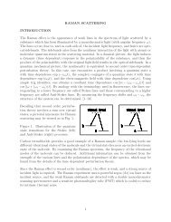
When an electron beam of energy around 20 keV strikes a metal target, two different<br />
processes produce x-<strong>ray</strong>s. In one process, the deceleration of beam electrons from<br />
collisions with the target produces a broad continuum of radiation called bremsstrahlung<br />
having a short wavelength limit that arises because the energy of the photon hc/ λ ¸can be<br />
no larger than the kinetic energy of the electron. In the other process, beam electrons<br />
knock atomic electrons in the target out of inner shells. When electrons from higher<br />
shells fall into the vacant inner shells, a series of discrete x<strong>ray</strong>s lines characteristic of the<br />
target material are emitted. In our machine, which has a copper target,only two emission<br />
lines are of appreciable intensity. Copper K α x-<strong>ray</strong>s (λ = 0:1542 nm) are produced when<br />
an n = 2 electron makes a transition to a vacancy in the n = 1 shell. A weaker K β x<strong>ray</strong><br />
with a shorter wavelength (λ = 0:1392 nm) occurs when the vacancy is filled by an n = 3<br />
electron.<br />
Thus, the spectrum of x-<strong>ray</strong>s from an x-<strong>ray</strong> tube consists of the discrete lines<br />
superimposed on the Bremsstrahlung continuum. This spectrum can be analyzed in much<br />
the same way that a visible spectrum is analyzed using a grating. Because x-<strong>ray</strong>s have<br />
much smaller wavelengths than visible light, the grating<br />
spacing must be much smaller. A single crystal with its regularly spaced, parallel planes<br />
of atoms is often used as a grating for x-<strong>ray</strong> spectroscopy. The incident x-<strong>ray</strong> wave is<br />
reflected specularly as it leaves the crystal planes, but most of the wave energy continues<br />
through to subsequent planes where additional reflected waves are produced. The path<br />
length difference for waves reflected from successive planes is 2d sin θ, where d is the<br />
distance between atomic planes. Note that the scattering angle (the angle between the<br />
original and outgoing <strong>ray</strong>s) is 2θ. Constructive interference of the reflected waves occurs<br />
when 2d sin θ is equal to an integer number of wavelengths nλ.<br />
For more detail about the theory, the Tel-X-Ometer manual has a lengthy explanation, as<br />
does the Art of Experimental Physics (excerpt from the textbook is linked here), which is<br />
available in hardcopy in the classroom. The first two chapters of C. Kittel, Introduction to<br />
Solid State Physics, or an equivalent text such as Fundamentals of Modern Physics by<br />
Eisberg also have good background on diffraction.<br />
In the Tel-X-Ometer, the x-<strong>ray</strong>s from the tube are collimated to a thick line and reflected<br />
from the crystal placed on the sample table. The detector, a Geiger-Muller (GM) tube, is<br />
placed behind collimating slits on the detector arm which can be placed at various<br />
scattering angles 2θ. In order to obey the Bragg condition, the crystal must rotate to an<br />
angle θ when the detector is at an angle 2 θ. This θ : 2 θ relationship is maintained by<br />
gears under the sample table.<br />
Equipment
• X-<strong>ray</strong> diffraction system (Tel-X-Ometer) experiment manual and its setup manual<br />
• Geiger-Müller tube and stepping motor<br />
• Computer and interface ( Labview software)<br />
• Alkali halide large single crystals<br />
• Radiation safety guide (just in case you want to know more)<br />
Theory Questions:<br />
What does the x-<strong>ray</strong> spectrum look like that is emitted from the x-<strong>ray</strong> tube?<br />
How does the Geiger-Müller tube work?<br />
Procedure<br />
1. Please read the Tel-X-Ometer setup manual (particularly sections 10.1-12.5), and<br />
any sections regarding safety features. Realize, you are working with a<br />
radioactive source, and thus should be aware of any possible hazards.<br />
2. Also read the Tel-X-Driver manual which explains how to use the software.<br />
3. To operate the Tel-X-Ometer:<br />
a. To open or close the scatter shield (the main cover), the whole shield must<br />
be displaced to the right or the left of center, depending on the position of<br />
the detector.<br />
b. To turn on the power to the unit, turn POWER ON key on the control<br />
panel; the unit will only function when the TIME SWITCH is rotated<br />
away from zero, and when the key is turned ON. This is to ensure that the<br />
x-<strong>ray</strong>s only turn on when enclosed within the leaded glass. The filament of<br />
the x-<strong>ray</strong> tube should then be illuminated. Wait 5 minutes, then depress the<br />
X-RAYS ON switch (the red light will turn on). If it does not turn on,<br />
wiggle the lid to ensure the metal pin is in the exact center.<br />
c. The Tel-atomic software (Tel-X-Driver v2.32 shortcut link on the<br />
Desktop) measures the counts from the Geiger-Mueller tube, the Geiger-<br />
Mueller tube’s voltage, and the current through the x-<strong>ray</strong> tube filament<br />
(this should be set to
maximum allowed angle should be about 115 degrees and the minimum<br />
should be 12.5 degrees (the arm cannot go below this angle).<br />
i. If the spectrum is shifted, decide the best course of action. Confirm<br />
this with your TA/Instructor BEFORE carrying out this action.<br />
b. When inserting the vertical collimating slits, you may adjust the<br />
number/position of these slits, but you should understand and describe in<br />
your report the consequence of the adjustments (both positive and negative<br />
consequences arise when slits are moved). Also, consider then angular<br />
accuracy possible given the size of the collimating slit closest to the<br />
Geiger-Mueller tube.<br />
c. When setting up the Carriage Arm you need to check two things:<br />
i. Make sure θ (written below the central gear) = ½ (2 θ) (which is<br />
written on the outer edge of the Tel-X-Ometer. If it doesn’t, rotate<br />
the sample holder using pliers (gently!)<br />
ii. Make sure that the set-angle in the software = 2θ written on the<br />
edge of the Tel-X-Ometer.<br />
5. Single Crystal <strong>Diffraction</strong> Experiments:<br />
For four of the large single crystal alkali halide samples provided (LiF,NaCl, KCl,<br />
or RbCl), collect the x-<strong>ray</strong> spectra using the Tel-X-Driver Software on the<br />
computer. Plot the spectra, and then determine in detail how the observed<br />
reflections relate to the real space structure of the crystal A detailed procedure for<br />
this is described in the Tel-X-Ometer manual, sections D.22-D.26. For purposes<br />
of plotting and analyzing your data you may wish to use one of the graphics<br />
packages available on the lab computers.<br />
Goals:<br />
References<br />
a. Quantify how the crystal spacing d changes with atomic number.<br />
i. What does the d spacing mean in terms of the crystal’s lattice<br />
constant?<br />
ii. Draw the crystal structure and label the d-spacing.<br />
iii. Compare the experimental value of the lattice constant to the<br />
published value.<br />
iv. If you rotated the crystal by 90°, would you get the same result? If<br />
you have time, try this experiment (D.25).<br />
v. What are the possible sources of error in this experiment?<br />
C. Kittel, Introduction to Solid State Physics, 6 th edition, Wiley, New York (1985).<br />
D. W. Preston and E. R. Deitz, The Art of Experimental Physics Wiley, New York<br />
(1991).<br />
R. Eisberg, Fundamentals of Modern Physics, Wiley, New York (1961).
R. Eisberg and R. Resnick, Quantum Physics of Atoms, Molecules, Solids, Nuclei and<br />
Particles, 2 nd edition, Wiley, New York (1985).<br />
B. E. Warren, X-Ray <strong>Diffraction</strong>, Addison-Wesley, Reading, MA (1969).<br />
International Tables for X-Ray Crystallography, Vol. 3, Reidel, Boston (1962).<br />
L. V. Azaroff and M. J. Buerger, The Powder Method in X-Ray Crystallography,<br />
MacGraw-Hill, New York (1958).<br />
P. J. Barry and A. D. Brothers, Am. J. Phys. 54, 186 (1986).