Static Electricity (Lab 01)
Static Electricity (Lab 01)
Static Electricity (Lab 01)

You also want an ePaper? Increase the reach of your titles
YUMPU automatically turns print PDFs into web optimized ePapers that Google loves.
We can also characterize how easily charge can flow along or through a material. Materials that<br />
easily allow charge to flow through them are known as conductors. Materials through which<br />
charge cannot easily flow are known as insulators. We understand this distinction today in terms<br />
of the mobility of charge carriers within the material. For instance, in most metals (which are<br />
often good conductors), valence electrons are free to move anywhere throughout the metal, and<br />
thus can easily transfer charge from one location to another within the metal. In insulating<br />
materials, on the other hand, there are relatively few free charge carriers, and so excess charge<br />
tends to stay where it’s put on the surface of an insulator. At an atomic level, though, we can still<br />
envision a process by which the electrons orbiting their nuclei in an insulator can shift somewhat<br />
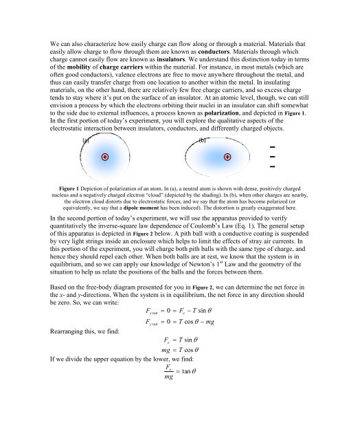
to the side due to external influences, a process known as polarization, and depicted in Figure 1.<br />
In the first portion of today’s experiment, you will explore the qualitative aspects of the<br />
electrostatic interaction between insulators, conductors, and differently charged objects.<br />
(a)<br />
(b)<br />
Figure 1 Depiction of polarization of an atom. In (a), a neutral atom is shown with dense, positively charged<br />
nucleus and a negatively charged electron “cloud” (depicted by the shading). In (b), when other charges are nearby,<br />
the electron cloud distorts due to electrostatic forces, and we say that the atom has become polarized (or<br />
equivalently, we say that a dipole moment has been induced). The distortion is greatly exaggerated here.<br />
In the second portion of today’s experiment, we will use the apparatus provided to verify<br />
quantitatively the inverse-square law dependence of Coulomb’s Law (Eq. 1). The general setup<br />
of this apparatus is depicted in Figure 2 below. A pith ball with a conductive coating is suspended<br />
by very light strings inside an enclosure which helps to limit the effects of stray air currents. In<br />
this portion of the experiment, you will charge both pith balls with the same type of charge, and<br />
hence they should repel each other. When both balls are at rest, we know that the system is in<br />
equilibrium, and so we can apply our knowledge of Newton’s 1 st Law and the geometry of the<br />
situation to help us relate the positions of the balls and the forces between them.<br />
Based on the free-body diagram presented for you in Figure 2, we can determine the net force in<br />
the x- and y-directions. When the system is in equilibrium, the net force in any direction should<br />
be zero. So, we can write:<br />
F 0 F T sin <br />
Rearranging this, we find:<br />
F<br />
x net<br />
y net<br />
e<br />
0 T cos mg<br />
T sin <br />
mg T cos <br />
If we divide the upper equation by the lower, we find:<br />
F e<br />
F e<br />
tan <br />
mg