User Manual - Holdan.eu
User Manual - Holdan.eu
User Manual - Holdan.eu

You also want an ePaper? Increase the reach of your titles
YUMPU automatically turns print PDFs into web optimized ePapers that Google loves.
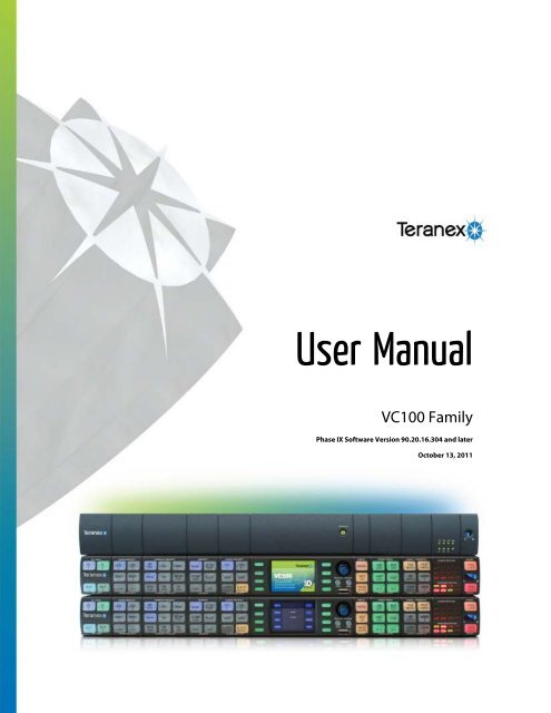
<strong>User</strong> <strong>Manual</strong><br />
VC100 Family<br />
Phase IX Software Version 90.20.16.304 and later<br />
October 13, 2011<br />
1
VC80, VC100, VC120 <strong>User</strong> <strong>Manual</strong><br />
Phase IX Software Version 90.20.16.304 and later<br />
Introduction.................................................................................................................................. 12<br />
Features: ....................................................................................................................................................13<br />
Overview....................................................................................................................................... 14<br />
Filters and Algorithms.................................................................................................................................14<br />
Block Diagram ............................................................................................................................................15<br />
Format Conversion Tables .........................................................................................................................17<br />
Packages....................................................................................................................................................25<br />
Options.......................................................................................................................................................25<br />
Applications ................................................................................................................................................27<br />
Aspect Ratio Conversion............................................................................................................................29<br />
Customer Support ....................................................................................................................... 31<br />
Connections................................................................................................................................. 32<br />
Rear Panel .................................................................................................................................................32<br />
Operation...................................................................................................................................... 36<br />
Local Control (Full) .....................................................................................................................................36<br />
Remote Control (Full) .................................................................................................................................36<br />
Status Front Panel......................................................................................................................................36<br />
Graphical <strong>User</strong> Interface.............................................................................................................................37<br />
Web <strong>User</strong> Interface ....................................................................................................................................37<br />
Local Control Panel Operation...................................................................................................38<br />
Control Panel Logic ....................................................................................................................................40<br />
Input/Output Section...................................................................................................................................41<br />
Video Select ...............................................................................................................................................43<br />
Format / Frame-rate Select ........................................................................................................................45<br />
Aspect ........................................................................................................................................................50<br />
Audio Select ...............................................................................................................................................53<br />
Graphical <strong>User</strong> Interface (GUI) and Menu Controls....................................................................................56<br />
Video Processing .......................................................................................................................................58<br />
Logo / Presets ............................................................................................................................................60<br />
Audio Status & System Status....................................................................................................................61<br />
Panel ..........................................................................................................................................................64<br />
Graphical <strong>User</strong> Interface / LCD Menu ........................................................................................ 65<br />
MAIN Menu ................................................................................................................................................66<br />
Video Menu................................................................................................................................... 67<br />
INPUT - Video Input Menu .........................................................................................................................68<br />
INPUT DETECT Menu................................................................................................................................................. 68<br />
NO INPUT Menu.......................................................................................................................................................... 69<br />
2
VC80, VC100, VC120 <strong>User</strong> <strong>Manual</strong><br />
Phase IX Software Version 90.20.16.304 and later<br />
PROC - Proc Amp Menu ............................................................................................................................70<br />
VIDEO - Video Gain Slider .......................................................................................................................................... 70<br />
BLACK - Black Level Slider ......................................................................................................................................... 71<br />
HUE - Hue Phase Slider .............................................................................................................................................. 71<br />
SATURATION - Saturation Level Slider ...................................................................................................................... 72<br />
R-Y - Level Slider......................................................................................................................................................... 72<br />
B-Y - Level Slider......................................................................................................................................................... 73<br />
RESET - Reset Proc Amp Menu ................................................................................................................................. 73<br />
ENH - Enhance Slider ................................................................................................................................75<br />
SHARP - Sharpness Slider.........................................................................................................................76<br />
ASPECT - Aspect Ratio Menu....................................................................................................................77<br />
H SIZE - Horizontal Size Slider.................................................................................................................................... 77<br />
V SIZE - Vertical Size Slider ........................................................................................................................................ 78<br />
H POS - Horizontal Position Slider .............................................................................................................................. 78<br />
V POS - Vertical Position Slider................................................................................................................................... 79<br />
H TRIM - Horizontal Trim Slider................................................................................................................................... 79<br />
V TRIM - Vertical Trim Slider ....................................................................................................................................... 80<br />
LINK – H & V Aspect Link (ON/OFF)........................................................................................................................... 80<br />
MORE - Aspect Ratio Menu - Page 2.........................................................................................................81<br />
SD FORMAT Menu...................................................................................................................................................... 81<br />
ACTIVE FILL Menu...................................................................................................................................................... 82<br />
TRIM Menu ........................................................................................................................................................... 83<br />
LEFT - Trim Left Slider.......................................................................................................................................... 83<br />
RIGHT - Trim Right Slider..................................................................................................................................... 84<br />
TOP - Trim Top Slider........................................................................................................................................... 84<br />
BOTTOM - Trim Bottom Slider.............................................................................................................................. 85<br />
SHIFT Menu.......................................................................................................................................................... 85<br />
FILL - Fill Color Sliders (Luma).................................................................................................................................... 86<br />
FILL - Fill Color Sliders (Cr) .................................................................................................................................. 86<br />
FILL - Fill Color Sliders (Cb) ................................................................................................................................. 87<br />
Z/C - Zoom/Crop Menu...............................................................................................................................88<br />
TEST - Test Pattern Generator Menu ........................................................................................................89<br />
SMPTE - Color Bars Menu .......................................................................................................................................... 89<br />
Audio Menu .................................................................................................................................. 90<br />
LEVEL - Audio Level Menu ........................................................................................................................91<br />
GROUP - Group Audio Level Menu............................................................................................................................. 92<br />
PAIR - Pair Audio Level Menu ..................................................................................................................................... 92<br />
CH - Channel Audio Level Menu ................................................................................................................................. 93<br />
PHASE - Audio Phase Menu......................................................................................................................94<br />
GROUP - Group Audio Phase Menu ........................................................................................................................... 94<br />
PAIR - Pair Audio Phase Menu ................................................................................................................................... 95<br />
3
VC80, VC100, VC120 <strong>User</strong> <strong>Manual</strong><br />
Phase IX Software Version 90.20.16.304 and later<br />
CH - Channels Audio Phase Menu.............................................................................................................................. 96<br />
ALL - Phase Audio Adjust............................................................................................................................................ 97<br />
DELAY - Audio Delay Menu .......................................................................................................................98<br />
MANUAL - <strong>Manual</strong> Audio Delay Menu ........................................................................................................................ 98<br />
uS - Microsecond Audio Delay Slider ................................................................................................................... 99<br />
mS - Millisecond Audio Delay Slider ..................................................................................................................... 99<br />
SEC - Second Audio Delay Slider....................................................................................................................... 100<br />
TEST - Audio Test Menu..........................................................................................................................101<br />
Select Audio Test Menu............................................................................................................................................. 101<br />
GROUP - Group Audio Test Menu ..................................................................................................................... 102<br />
PAIR - Pair Audio Test Menu.............................................................................................................................. 102<br />
CH - Channels Audio Test Menu ........................................................................................................................ 103<br />
ALL - Test Audio Enable Menu ........................................................................................................................... 104<br />
Advanced Menu ......................................................................................................................... 105<br />
NR - Noise Reduction Menu.....................................................................................................................106<br />
NR - Noise Reduction Enable Menu.......................................................................................................................... 106<br />
NR BIAS - Noise Reduction Bias Level Slider........................................................................................................... 107<br />
SPLIT - Split Screen Menu ........................................................................................................................................ 108<br />
RED - Red Overlay Menu .......................................................................................................................................... 108<br />
SOURCE Menu ........................................................................................................................................110<br />
COLOR CORRECT Menu........................................................................................................................111<br />
Color Correct Sliders (Red) ....................................................................................................................................... 111<br />
Color Correct Sliders (Green) .................................................................................................................................... 111<br />
Color Correct Sliders (Blue)....................................................................................................................................... 112<br />
APER - Aperture Menu.............................................................................................................................113<br />
CLIP - Clip Video Menu............................................................................................................................114<br />
Y HIGH - Y High Clip Slider ....................................................................................................................................... 114<br />
Y LOW - Y Low Clip Slider......................................................................................................................................... 115<br />
C HIGH - C High Clip Slider....................................................................................................................................... 115<br />
C LOW - C Low Clip Slider ........................................................................................................................................ 116<br />
SCENE CUT Menu...................................................................................................................................117<br />
TVP Menu ................................................................................................................................................117<br />
CADENCE - Clean Cadence Menu ..........................................................................................................118<br />
RP177 Menu ..................................................................................................................................................................... 118<br />
Setup Menu ................................................................................................................................ 119<br />
REF 1 - Reference 1 Menu.......................................................................................................................120<br />
BLACK Menu ............................................................................................................................................................. 121<br />
PIXEL - Blackburst Signal Pixel Timing Slider .................................................................................................... 121<br />
LINE - Blackburst Signal Line Timing Slider ....................................................................................................... 122<br />
TRI - I - Interlaced Tri-level Signal Menu ................................................................................................................... 122<br />
PIXEL - Interlaced Signal Pixel Timing Slider ..................................................................................................... 123<br />
4
VC80, VC100, VC120 <strong>User</strong> <strong>Manual</strong><br />
Phase IX Software Version 90.20.16.304 and later<br />
LINE - Interlaced Signal Line Timing Slider ........................................................................................................ 123<br />
TRI - P - Progressive Tri-level Signal Menu .............................................................................................................. 124<br />
PIXEL - Progressive Signal Pixel Timing Slider.................................................................................................. 124<br />
LINE - Progressive Signal Line Timing Slider ..................................................................................................... 125<br />
REF 2 - Reference 2 Menu.......................................................................................................................126<br />
AUDIO - Setup Audio Menu .....................................................................................................................127<br />
EMBED - Embedded Audio Channel Allocation Menu .............................................................................................. 127<br />
DOLBY - Dolby Setup Menu...................................................................................................................................... 128<br />
DECODE - Dolby Decoding Menu ...................................................................................................................... 128<br />
INPUT - Dolby Input Menu.................................................................................................................................. 129<br />
Out Map (Dolby) Menu .............................................................................................................................................. 130<br />
AUTO PHASE Menu.................................................................................................................................................. 131<br />
AES Menu.................................................................................................................................................................. 131<br />
AES TYPE .......................................................................................................................................................... 132<br />
AES CHAN.......................................................................................................................................................... 132<br />
ANALOG - Analog Audio Setup Menu....................................................................................................................... 133<br />
O/P - Analog Audio Output Reference Level Menu ............................................................................................ 133<br />
CHAN - Analog Audio Channel Allocation Menu ................................................................................................ 134<br />
ANC - Ancillary Data Menu.......................................................................................................................135<br />
TC - Timecode Menu ................................................................................................................................................. 135<br />
TC OUT - Timecode Output Slider...................................................................................................................... 136<br />
CC - Closed Caption Menu........................................................................................................................................ 136<br />
IN - Closed Caption Input Slider ......................................................................................................................... 137<br />
OUT - Closed Caption Output Slider................................................................................................................... 137<br />
DET FLD 2 - Detect Field 2 Menu....................................................................................................................... 138<br />
CC - Closed Caption Enable Menu..................................................................................................................... 138<br />
INDEX Menu.............................................................................................................................................................. 139<br />
AFD - Active Format Description Menu .............................................................................................................. 139<br />
INSERT - AFD Insert Menu ................................................................................................................................ 140<br />
OUTPUT LINE - AFD Output Line Slider ............................................................................................................ 140<br />
REACT - AFD React Menu ................................................................................................................................. 141<br />
CMPNT - Analog Component I/O Menu ...................................................................................................142<br />
INPUT - Analog Component Input Menu ................................................................................................................... 142<br />
CMPST - Composite Video Setup Menu ..................................................................................................143<br />
INPUT - Composite Input Menu................................................................................................................................. 143<br />
INPUT FILTER Menu.......................................................................................................................................... 144<br />
SETUP LEVEL - Composite Input Setup Level Menu ........................................................................................ 144<br />
AGC - Automatic Gain Control Menu.................................................................................................................. 145<br />
LUMA COMB Menu ............................................................................................................................................ 145<br />
CHROMA COMB Menu ...................................................................................................................................... 146<br />
OUTPUT - Composite Output Setup Menu ............................................................................................................... 146<br />
SETUP LEVEL - Composite Output Setup Level Menu...................................................................................... 147<br />
5
VC80, VC100, VC120 <strong>User</strong> <strong>Manual</strong><br />
Phase IX Software Version 90.20.16.304 and later<br />
GPI - General Purpose Interface Menu ....................................................................................................148<br />
GPI 1 - GPI Channel Selection Menu ........................................................................................................................ 148<br />
CH1 - GPI Select Preset Menu ........................................................................................................................... 149<br />
PRESET 1 - GPI Preset Type Menu................................................................................................................... 149<br />
MORE - Setup Menu page 2 ....................................................................................................................150<br />
KEY - License Key Menu..........................................................................................................................151<br />
CONFIRM - License Key Confirm Menu.................................................................................................................... 151<br />
RMT IP - Remote IP Address Menu .........................................................................................................152<br />
MANUAL - Remote IP Address Menu ....................................................................................................................... 152<br />
IP - IP Address Menu ...............................................................................................................................153<br />
DHCP Menu............................................................................................................................................................... 153<br />
STATIC IP Menu........................................................................................................................................................ 154<br />
SUBNET - Subnet IP Address Menu ......................................................................................................................... 154<br />
PNL IP - Control Panel IP Address Menu.................................................................................................155<br />
DHCP Menu............................................................................................................................................................... 155<br />
STATIC IP - Static Panel IP Address Menu............................................................................................................... 156<br />
SUBNET - Panel Subnet IP Address Menu............................................................................................................... 156<br />
RS PORT - Serial Port Menu....................................................................................................................157<br />
RS232 Menu.............................................................................................................................................................. 157<br />
BAUD - RS232 Baud Rate Menu........................................................................................................................ 158<br />
PARITY - RS232 Parity Menu............................................................................................................................. 158<br />
STOP BIT - RS232 Stop Bit Menu...................................................................................................................... 159<br />
RESET - Internal Storage Formating Menu..............................................................................................160<br />
Logo Menu.................................................................................................................................. 161<br />
USB Menu ................................................................................................................................................162<br />
POS - Logo Position Menu.......................................................................................................................163<br />
X - Logo X Position Slider.......................................................................................................................................... 163<br />
Y - Logo Y Position Slider.......................................................................................................................................... 164<br />
TRANSPARENT COLOR - RED Slider ....................................................................................................165<br />
TRANSPARENT COLOR - GREEN Slider...............................................................................................166<br />
TRANSPARENT COLOR - BLUE Slider .................................................................................................167<br />
OPAQUE..................................................................................................................................................168<br />
3D Menu...................................................................................................................................... 169<br />
ENCODE - 3D Encoder Application (VC1-3D-ENC) Menu.......................................................................170<br />
MODE - 3D Encode Mode ......................................................................................................................................... 170<br />
AUDIO - 3D Encode Audio Menu .............................................................................................................................. 171<br />
DECODE - 3D Decoder Application (VC1-3D-DEC) Menu.......................................................................172<br />
MODE - 3D Decode Mode......................................................................................................................................... 173<br />
AUDIO ....................................................................................................................................................................... 173<br />
2D >3D - 2D to 3D Menu (Option: VC1-2D-3D) ....................................................................................174<br />
6
VC80, VC100, VC120 <strong>User</strong> <strong>Manual</strong><br />
Phase IX Software Version 90.20.16.304 and later<br />
MODE ........................................................................................................................................................................ 174<br />
INTENSITY Slider...................................................................................................................................................... 175<br />
DEPTH....................................................................................................................................................................... 175<br />
3D LOGO................................................................................................................................................................... 176<br />
DEPTH Slider...................................................................................................................................................... 176<br />
POS .................................................................................................................................................................... 177<br />
X – 3D Logo X Position Slider............................................................................................................................. 177<br />
Y – 3D Logo Y Position Slider............................................................................................................................. 178<br />
AUDIO – 3D Audio Menu........................................................................................................................................... 178<br />
3D Sync Application Menu (Option: VC1-3D-SYNC)................................................................................179<br />
REF – External Reference 1 Setup Menu ................................................................................................................. 179<br />
Preset Menu ............................................................................................................................... 180<br />
PRESETS – Standard and 3D Preset Menus...........................................................................................181<br />
PRESET1 Menu ........................................................................................................................................................ 181<br />
RECALL FULL Menu ................................................................................................................................................. 182<br />
RECALL BASIC Menu ............................................................................................................................................... 182<br />
SAVE Menu ............................................................................................................................................................... 183<br />
DEFAULT – Default (power-on) Recall/Save Menu .................................................................................183<br />
DEFAULT RECALL (YES/NO) Menu ........................................................................................................................ 184<br />
DEFAULT SAVE (YES/NO) Menu............................................................................................................................. 184<br />
USB - USB Load/Save Menu ...................................................................................................................185<br />
LOAD USB - USB Load Location Menu .................................................................................................................... 185<br />
SAVE USB - USB Save Location Menu .................................................................................................................... 186<br />
Help Menu................................................................................................................................... 187<br />
SW Menu..................................................................................................................................................188<br />
HW Menu .................................................................................................................................................189<br />
MODULE Menu ........................................................................................................................................190<br />
DEMO MODE Menu.................................................................................................................................191<br />
PKG - Packages Menu.............................................................................................................................192<br />
IP/MAC Menu ...........................................................................................................................................193<br />
SVRC - Service Menu .............................................................................................................................194<br />
KEY - Save / Load KEY Menu ................................................................................................................................... 194<br />
VC80 Status Front Panel........................................................................................................... 195<br />
Web-based Operation ............................................................................................................... 196<br />
Web Interface / Set an IP Static Address .................................................................................................197<br />
VC80, VC100 & VC120 specific functions................................................................................................198<br />
Current Settings / Pending Selections......................................................................................................199<br />
Web Interface Header ..............................................................................................................................200<br />
I/O Settings menu.....................................................................................................................................201<br />
Video Settings menu ................................................................................................................................203<br />
7
VC80, VC100, VC120 <strong>User</strong> <strong>Manual</strong><br />
Phase IX Software Version 90.20.16.304 and later<br />
Proc Amp tab ............................................................................................................................................................. 203<br />
Variable Aspect tab.................................................................................................................................................... 204<br />
Fill Shade tab............................................................................................................................................................. 205<br />
Test Patterns tab ....................................................................................................................................................... 206<br />
Audio Settings menu ................................................................................................................................207<br />
Audio Level ................................................................................................................................................................ 207<br />
Embedded ................................................................................................................................................................. 208<br />
Dolby.......................................................................................................................................................................... 208<br />
Analog........................................................................................................................................................................ 209<br />
Mapping ..................................................................................................................................................................... 209<br />
Advanced Settings menu..........................................................................................................................210<br />
Noise Reduction ........................................................................................................................................................ 210<br />
Color Correction......................................................................................................................................................... 210<br />
Clip............................................................................................................................................................................. 211<br />
More........................................................................................................................................................................... 211<br />
Setup menu ..............................................................................................................................................212<br />
Reference .................................................................................................................................................................. 212<br />
Closed Caption .......................................................................................................................................................... 213<br />
Time Code ................................................................................................................................................................. 213<br />
Video Indexing ........................................................................................................................................................... 214<br />
Cmpst/Cmpnt............................................................................................................................................................. 215<br />
GPI............................................................................................................................................................................. 216<br />
More........................................................................................................................................................................... 217<br />
Logos .......................................................................................................................................................218<br />
3D menu...................................................................................................................................................219<br />
2D -> 3D .................................................................................................................................................................... 219<br />
3D ENC...................................................................................................................................................................... 220<br />
3D DEC...................................................................................................................................................................... 221<br />
3D SYNC ................................................................................................................................................................... 222<br />
Presets menu ...........................................................................................................................................223<br />
Info/Status menu ......................................................................................................................................224<br />
System Info................................................................................................................................................................ 224<br />
Keying/Packaging ...................................................................................................................................................... 224<br />
System Status............................................................................................................................................................ 225<br />
Current Configuration ................................................................................................................................................ 225<br />
Network...................................................................................................................................................................... 226<br />
Appendix A - Audio Cables ...................................................................................................... 227<br />
Cables & Pin-outs.....................................................................................................................................227<br />
Appendix B - Preset Files ......................................................................................................... 230<br />
Basic <strong>User</strong> Presets...................................................................................................................................230<br />
Appendix C - RS232/RS422 Port .............................................................................................. 231<br />
8
VC80, VC100, VC120 <strong>User</strong> <strong>Manual</strong><br />
Phase IX Software Version 90.20.16.304 and later<br />
Appendix D - GPI ....................................................................................................................... 232<br />
Appendix E - Directory Structure............................................................................................. 233<br />
On USB Storage Device ............................................................................................................................................ 233<br />
Appendix F - Video Indexing .................................................................................................... 234<br />
Wide Screen Signaling (WSS)..................................................................................................................234<br />
Video Index Information Coding ...............................................................................................................235<br />
Active Format Description (AFD)..............................................................................................................236<br />
AFD Insertion - Automatic Mode................................................................................................................................ 236<br />
AFD Insertion codes for a 4:3 output frame............................................................................................................... 237<br />
AFD Insertion codes for a 16:9 output frame............................................................................................................. 238<br />
AFD Reaction Codes for a 4:3 coded frame.............................................................................................................. 239<br />
AFD Reaction Codes for a 16:9 coded frame............................................................................................................ 240<br />
Appendix G - Guidelines for Logo Creation ........................................................................... 241<br />
Loading Logo Files via USB ...................................................................................................................................... 241<br />
Appendix H - System Specifications ....................................................................................... 242<br />
9
VC80, VC100, VC120 <strong>User</strong> <strong>Manual</strong><br />
Phase IX Software Version 90.20.16.304 and later<br />
This page is left intentionally blank<br />
10
VC80, VC100, VC120 <strong>User</strong> <strong>Manual</strong><br />
Phase IX Software Version 90.20.16.304 and later<br />
11
VC80, VC100, VC120 <strong>User</strong> <strong>Manual</strong><br />
Phase IX Software Version 90.20.16.304 and later<br />
Introduction<br />
The VC100 Family of frame synchronizers and format converters brings legendary Teranex image quality to<br />
the Broadcasting world. The VC100 is packed with proprietary Teranex technology, like PixelMotion Deinterlacing<br />
and Multi-Directional Diagonal Filtering (MDDFTM) algorithms, drastically reducing jaggies on<br />
diagonal lines. Teranex’s Per-Pixel Temporal Recursive Noise Reduction algorithm minimizes HD and SD<br />
video noise. Correct cadence is assured through Teranex’s Per-Pixel Video/Film detection. Teranex image<br />
processing technology yields unsurpassed image quality for the demanding Broadcaster.<br />
The Dual REALTA architecture includes the industry’s first fully software programmable video array<br />
processor capable of performing over 1 trillion operations per second per chip. In addition, it performs endto-end,<br />
true 10-bit image processing. The powerful Teranex Video Processor (TVP) core built into the Realta<br />
ensures flexibility and future proofing by enabling subsequent software improvements without making<br />
hardware obsolete. The Dual-Realta Module supports a 32-bit data path, assignable as 30-bit YCrCb or<br />
RGB.<br />
This flexible frame synchronizer can handle just about any signal at its inputs and outputs, in either SD, HD<br />
or 3G formats. The VC100 uses two Silicon Optix Realta image processing engines, reducing overall size<br />
while maximizing image processing capability. The result? The best possible picture from the most flexible,<br />
powerful, and user-friendly frame synchronizer available today, all in a space-saving 1RU design.<br />
Proud of its rich heritage, Teranex now expands the VC100 product into a product family, with the<br />
introduction of the affordable VC80 and unbeatable VC120 Universal frame synchronizer and format<br />
converters.<br />
VC80<br />
The VC80 is an entry level dual-channel Universal frame synchronizer and format converter for cost<br />
sensitive applications. Born of the same technology found in the VC100, it provides exceptional image<br />
quality and flexibility. The VC80 is equipped with many of the features of the VC100, such as the availability<br />
of 16 channels of embedded audio per processing video channel, video indexing support like; Active Format<br />
Description, (AFD) and full SD & HD closed caption processing. With 48 format conversions, the VC80 has<br />
the highest number of conversions in its class. And because it is part of the VC100 product family, its<br />
capabilities are expandable; users can increase their VC80's capabilities to any VC100 product family<br />
functionality by adding software or hardware options as needed.<br />
VC100<br />
The VC100 is the workhorse of the VC100 product family with 107 format conversions in its basic form,<br />
expandable to 257. The VC100 is at home in both post production and broadcast facilities and comes in<br />
single or dual channel configuration, with available composite/component video I/O, analog/AES audio I/O<br />
and expanded format and frame rate conversion support, including HD Linear Standards conversion. The<br />
VC100 is an essential addition to any facility looking to handle any conversion or signal interfacing<br />
requirement.<br />
VC120<br />
The VC120 is the ultimate Universal frame synchronizer and format converter, with standard 3G and 4:4:4<br />
capabilities. This platform supports 122 format conversions in its basic form and is expandable to 275, the<br />
largest number of conversions available today. Just like the VC100; it is available in single or dual channel<br />
configuration and supports HD Linear Standards Conversions.<br />
12
VC80, VC100, VC120 <strong>User</strong> <strong>Manual</strong><br />
Phase IX Software Version 90.20.16.304 and later<br />
Features:<br />
VC100 Family Features:<br />
<br />
<br />
<br />
<br />
<br />
<br />
<br />
<br />
<br />
<br />
<br />
Updates Available Online<br />
Aspect Ratio Conversion with Active Fill Information<br />
Video Indexing with Active Format Description (AFD)<br />
Full SD 608 & HD 708 Closed Caption Conversion Support<br />
Local Control Panel LCD Serves as a Video I/O Monitor & Menu Display<br />
Full Web Server Control - Click here to see a demo (Need a internet connection - Not compatible<br />
with Internet Explorer)<br />
Color Correction & Logo Insertion<br />
Integrated Video & Audio Test Signal & Time Code Generators<br />
Discreet Audio Gain, Delay & Phase Controls<br />
Redundant Power Supplies<br />
VC100 Family Optional Features:<br />
<br />
<br />
<br />
<br />
<br />
<br />
<br />
<br />
<br />
Remote Control Panel<br />
AES/Analog Audio I/O<br />
Audio Expansion Module<br />
Dolby E decoding<br />
Analog Composite & Component Video I/O<br />
3G-SDI I/O<br />
Temporal Recursive Noise Reduction<br />
Expanded Format & Frame Rate Conversions with SD/HD Standards Conversions<br />
Typical Applications<br />
<br />
<br />
<br />
<br />
<br />
<br />
<br />
<br />
Network Feed Centers<br />
Mobile Truck Applications<br />
International Broadcast Exchange SD/HD Linear Standards Conversion<br />
HD Broadcast Exchange Cross Conversion<br />
Frame Synchronized SD Video Signal Up Conversion To HD Switchers<br />
Frame Synchronized HD Video Down Conversion<br />
Frame Synchronized SD/HD VTR Conversion and Monitoring<br />
Frame Synchronized SD/HD Video Noise Cleaning<br />
13
VC80, VC100, VC120 <strong>User</strong> <strong>Manual</strong><br />
Phase IX Software Version 90.20.16.304 and later<br />
Overview<br />
Filters and Algorithms<br />
PixelMotion De-interlacing<br />
PixelMotion de-interlacing of video originated material produces perfect progressive frames in preparation<br />
for further processing. The processing aperture is adjusted on a pixel-by-pixel basis, which preserves all of<br />
the detail of the original interlaced image and eliminates jaggies in the output image.<br />
Aspect Ratio Control<br />
The VC100 offers selection from standard aspect ratios, such as common top & bottom, common sides,<br />
14:9 and Anamorphic. In addition, Flexview, a non-linear anamorphic aspect ratio used in upconversions,<br />
offers smart 4:3 to 16:9 aspect ratio conversion.<br />
Detail Enhancement<br />
The edge-sharpening filter used for Detail Enhancement is based on a traditional film compositing technique<br />
called "Unsharp Masking." This filter corrects any blurring introduced during image capture, compression or<br />
resampling.<br />
Noise Reduction<br />
Adjustable noise reduction controls offer a greater degree of temporal recursive noise reduction with fewer<br />
artifacts. A bias control allows the aggressiveness to be fine-tuned. For filter performance testing, a Red<br />
Overlay can be applied that will color pixels that are in motion in Red.<br />
14
VC80, VC100, VC120 <strong>User</strong> <strong>Manual</strong><br />
Phase IX Software Version 90.20.16.304 and later<br />
Block Diagram<br />
VC80<br />
15
VC80, VC100, VC120 <strong>User</strong> <strong>Manual</strong><br />
Phase IX Software Version 90.20.16.304 and later<br />
VC100<br />
VC120<br />
16
VC80, VC100, VC120 <strong>User</strong> <strong>Manual</strong><br />
Phase IX Software Version 90.20.16.304 and later<br />
Format Conversion Tables<br />
Base VC80 Format Conversions<br />
Input Output Input Output<br />
480i59.94 480i59.94<br />
720p59.94<br />
1080i59.94<br />
1080p59.94<br />
1080sf23.98<br />
576i50<br />
576i50<br />
720p50<br />
1080i50<br />
1080p50<br />
1080sf25<br />
720p59.94 480i59.94<br />
720p59.94<br />
1080i59.94<br />
1080p59.94<br />
1080sf23.98<br />
1080i50<br />
576i50<br />
720p50<br />
1080i50<br />
1080p50<br />
1080sf25<br />
1080i60 480i59.94<br />
720p59.94<br />
1080i59.94<br />
1080p59.94<br />
1080sf23.98<br />
1080sf24 480i59.94<br />
720p59.94<br />
1080i59.94<br />
1080p59.94<br />
1080sf24<br />
1080p50<br />
576i50<br />
720p50<br />
1080i50<br />
1080p50<br />
- Available when OPTIONAL VC1-3GIO module is installed.<br />
480i60 480i59.94<br />
720p59.94<br />
1080i59.94<br />
1080p59.94<br />
1080sf23.98<br />
720p50<br />
576i50<br />
720p50<br />
1080i50<br />
1080p50<br />
1080sf25<br />
720p60 480i59.94<br />
720p59.94<br />
1080i59.94<br />
1080p59.94<br />
1080sf23.98<br />
1080i59.94 480i59.94<br />
720p59.94<br />
1080i59.94<br />
1080p59.94<br />
1080sf23.98<br />
1080sf23.98 480i59.94<br />
720p59.94<br />
1080i59.94<br />
1080p59.94<br />
1080sf23.98<br />
1080sf25<br />
576i50<br />
720p50<br />
1080i50<br />
1080p50<br />
1080sf25<br />
1080p59.94 480i59.94<br />
720p59.94<br />
1080i59.94<br />
1080p59.94<br />
17
VC80, VC100, VC120 <strong>User</strong> <strong>Manual</strong><br />
Phase IX Software Version 90.20.16.304 and later<br />
Base VC100 Format Conversions<br />
Input Output Input Output<br />
480i59.94 480i59.94<br />
576sf23.98<br />
720p59.94<br />
1080i59.94<br />
1080p59.94<br />
1080sf23.98<br />
1080p23.98<br />
1080sf29.97<br />
1080p29.97<br />
576i50<br />
576i50<br />
720p50<br />
1080i50<br />
1080p50<br />
1080sf25<br />
1080p25<br />
720p50<br />
576i50<br />
720p50<br />
1080i50<br />
1080p50<br />
1080sf25<br />
1080p25<br />
720p60 480i59.94<br />
576sf23.98<br />
720p59.94<br />
1080i59.94<br />
1080p59.94<br />
1080sf23.98<br />
1080p23.98<br />
1080sf29.97<br />
1080p29.97<br />
1080i59.94 480i59.94<br />
576sf23.98<br />
720p59.94<br />
1080i59.94<br />
1080p59.94<br />
1080sf23.98<br />
1080p23.98<br />
1080sf29.97<br />
1080p29.97<br />
1080sf23.98 480i59.94<br />
576sf23.98<br />
720p59.94<br />
1080i59.94<br />
1080p59.94<br />
1080sf23.98<br />
1080p23.98<br />
1080sf24<br />
1080sf24<br />
1080p24<br />
480i60 480i59.94<br />
576sf23.98<br />
720p59.94<br />
1080i59.94<br />
1080p59.94<br />
1080sf23.98<br />
1080p23.98<br />
1080sf29.97<br />
1080p29.97<br />
576sf23.98 480i59.94<br />
576sf23.98<br />
720p59.94<br />
1080i59.94<br />
1080sf23.98<br />
1080p23.98<br />
720p59.94 480i59.94<br />
576sf23.98<br />
720p59.94<br />
1080i59.94<br />
1080p59.94<br />
1080sf23.98<br />
1080p23.98<br />
1080sf29.97<br />
1080p29.97<br />
1080i50<br />
576i50<br />
720p50<br />
1080i50<br />
1080p50<br />
1080sf25<br />
1080p25<br />
1080i60 480i59.94<br />
576sf23.98<br />
720p59.94<br />
1080i59.94<br />
1080p59.94<br />
1080sf23.98<br />
1080p23.98<br />
1080sf29.97<br />
1080p29.97<br />
1080p23.98 480i59.94<br />
576sf23.98<br />
720p59.94<br />
1080i59.94<br />
1080p59.94<br />
1080sf23.98<br />
1080p23.98<br />
1080p24<br />
1080sf24<br />
1080p24<br />
Continued on next page…<br />
18
VC80, VC100, VC120 <strong>User</strong> <strong>Manual</strong><br />
Phase IX Software Version 90.20.16.304 and later<br />
Base VC100 Format Conversions (continued)<br />
Input Output Input Output<br />
1080sf25<br />
576i50<br />
720p50<br />
1080i50<br />
1080p50<br />
1080sf25<br />
1080p25<br />
1080sf29.97 480i59.94<br />
720p59.94<br />
1080i59.94<br />
1080p59.94<br />
1080sf29.97<br />
1080p29.97<br />
1080p50<br />
576i50<br />
720p50<br />
1080i50<br />
1080p50<br />
1080sf25<br />
1080p25<br />
- Available when OPTIONAL VC1-3GIO module is installed<br />
1080p25<br />
576i50<br />
720p50<br />
1080i50<br />
1080p50<br />
1080sf25<br />
1080p25<br />
1080p29.97 480i59.94<br />
720p59.94<br />
1080i59.94<br />
1080p59.94<br />
1080sf29.97<br />
1080p29.97<br />
1080p59.94 480i59.94<br />
576sf23.98<br />
720p59.94<br />
1080i59.94<br />
1080p59.94<br />
1080sf23.98<br />
1080p23.98<br />
1080sf29.97<br />
1080p29.97<br />
19
VC80, VC100, VC120 <strong>User</strong> <strong>Manual</strong><br />
Phase IX Software Version 90.20.16.304 and later<br />
Base VC120 Format Conversions<br />
Input Output Input Output<br />
480i59.94 480i59.94<br />
576sf23.98<br />
720p59.94<br />
1080i59.94<br />
1080p59.94<br />
1080sf23.98<br />
1080p23.98<br />
1080sf29.97<br />
1080p29.97<br />
576i50<br />
576i50<br />
720p50<br />
1080i50<br />
1080p50<br />
1080sf25<br />
1080p25<br />
720p50<br />
576i50<br />
720p50<br />
1080i50<br />
1080p50<br />
1080sf25<br />
1080p25<br />
720p60 480i59.94<br />
576sf23.98<br />
720p59.94<br />
1080i59.94<br />
1080p59.94<br />
1080sf23.98<br />
1080p23.98<br />
1080sf29.97<br />
1080p29.97<br />
1080i59.94 480i59.94<br />
576sf23.98<br />
720p59.94<br />
1080i59.94<br />
1080p59.94<br />
1080sf23.98<br />
1080p23.98<br />
1080sf29.97<br />
1080p29.97<br />
1080sf23.98 480i59.94<br />
576sf23.98<br />
720p59.94<br />
1080i59.94<br />
1080p59.94<br />
1080sf23.98<br />
1080p23.98<br />
1080sf24<br />
1080sf24<br />
1080p24<br />
480i60 480i59.94<br />
576sf23.98<br />
720p59.94<br />
1080i59.94<br />
1080p59.94<br />
1080sf23.98<br />
1080p23.98<br />
1080sf29.97<br />
1080p29.97<br />
576sf23.98 480i59.94<br />
576sf23.98<br />
720p59.94<br />
1080i59.94<br />
1080sf23.98<br />
1080p23.98<br />
720p59.94 480i59.94<br />
576sf23.98<br />
720p59.94<br />
1080i59.94<br />
1080p59.94<br />
1080sf23.98<br />
1080p23.98<br />
1080sf29.97<br />
1080p29.97<br />
1080i50<br />
576i50<br />
720p50<br />
1080i50<br />
1080p50<br />
1080sf25<br />
1080p25<br />
1080i60 480i59.94<br />
576sf23.98<br />
720p59.94<br />
1080i59.94<br />
1080p59.94<br />
1080sf23.98<br />
1080p23.98<br />
1080sf29.97<br />
1080p29.97<br />
1080p23.98 480i59.94<br />
576sf23.98<br />
720p59.94<br />
1080i59.94<br />
1080p59.94<br />
1080sf23.98<br />
1080p23.98<br />
1080p24<br />
1080sf24<br />
1080p24<br />
Continued on next page…<br />
20
VC80, VC100, VC120 <strong>User</strong> <strong>Manual</strong><br />
Phase IX Software Version 90.20.16.304 and later<br />
Base VC120 Format Conversions (continued)<br />
INPUT OUTPUT INPUT OUTPUT<br />
1080sf25<br />
576i50<br />
720p50<br />
1080i50<br />
1080p50<br />
1080sf25<br />
1080p25<br />
1080sf29.97 480i59.94<br />
720p59.94<br />
1080i59.94<br />
1080p59.94<br />
1080sf29.97<br />
1080p29.97<br />
1080p50<br />
576i50<br />
720p50<br />
1080i50<br />
1080p50<br />
1080sf25<br />
1080p25<br />
1080p25<br />
576i50<br />
720p50<br />
1080i50<br />
1080p50<br />
1080sf25<br />
1080p25<br />
1080p29.97 480i59.94<br />
720p59.94<br />
1080i59.94<br />
1080p59.94<br />
1080sf29.97<br />
1080p29.97<br />
1080p59.94 480i59.94<br />
576sf23.98<br />
720p59.94<br />
1080i59.94<br />
1080p59.94<br />
1080sf23.98<br />
1080p23.98<br />
1080sf29.97<br />
1080p29.97<br />
21
VC80, VC100, VC120 <strong>User</strong> <strong>Manual</strong><br />
Phase IX Software Version 90.20.16.304 and later<br />
Available SD Standards Conversions (Option: VC1-SDSTDS-1CH, -2CH)<br />
Input Output Input Output<br />
480i59.94 576i50<br />
720p50<br />
1080i50<br />
1080p50<br />
1080sf24<br />
1080p24<br />
1080sf25<br />
1080p25<br />
576i50 480i59.94<br />
720p59.94<br />
1080i59.94<br />
1080p59.94<br />
1080sf23.98<br />
1080p23.98<br />
1080sf24<br />
1080p24<br />
1080sf29.97<br />
1080p29.97<br />
480i60<br />
- Available in VC80/100 (with 3GIO board installed) and in VC120<br />
576i50<br />
720p50<br />
1080i50<br />
1080p50<br />
1080sf24<br />
1080p24<br />
1080sf25<br />
1080p25<br />
720p50 480i59.94<br />
720p59.94 576i50 720p60 576i50<br />
1080i50 480i59.94 1080i59.94 576i50<br />
1080i60 576i50 1080sf23.98 576i50<br />
1080p23.98 576i50 1080sf24 480i59.94<br />
576i50<br />
1080p24 480i59.94<br />
576i50<br />
1080sf25 480i59.94<br />
1080p25 480i59.94 1080sf29.97 576i50<br />
1080p29.97 576i50<br />
22
VC80, VC100, VC120 <strong>User</strong> <strong>Manual</strong><br />
Phase IX Software Version 90.20.16.304 and later<br />
Available SD/HD Standards Conversions (Option: VC1-HDSTDS-1CH, -2CH)<br />
Input Output Input Output<br />
480i59.94 576i50<br />
720p50<br />
1080i50<br />
1080p50<br />
1080sf24<br />
1080p24<br />
1080sf25<br />
1080p25<br />
576i50 480i59.94<br />
720p59.94<br />
1080i59.94<br />
1080p59.94<br />
1080sf23.98<br />
1080p23.98<br />
1080sf24<br />
1080p24<br />
1080sf29.97<br />
1080p29.97<br />
720p59.94 576i50<br />
720p50<br />
1080i50<br />
1080p50<br />
1080sf23.98<br />
1080p23.98<br />
1080sf24<br />
1080p24<br />
1080sf25<br />
1080p25<br />
1080i50 480i59.94<br />
720p59.94<br />
1080i59.94<br />
1080p59.94<br />
1080sf23.98<br />
1080p23.98<br />
1080sf24<br />
1080p24<br />
1080sf29.97<br />
1080p29.97<br />
1080i60<br />
576i50<br />
720p50<br />
1080i50<br />
1080p50<br />
1080sf24<br />
1080p24<br />
1080sf25<br />
1080p25<br />
1080p23.98 576i50<br />
720p50<br />
1080i50<br />
1080p50<br />
1080sf24<br />
1080p24<br />
1080sf25<br />
1080p25<br />
1080sf29.97<br />
1080p29.97<br />
Continued on next page…<br />
480i60<br />
576i50<br />
720p50<br />
1080i50<br />
1080p50<br />
1080sf24<br />
1080p24<br />
1080sf25<br />
1080p25<br />
720p50 480i59.94<br />
720p59.94<br />
1080i59.94<br />
1080p59.94<br />
1080sf23.98<br />
1080p23.98<br />
1080sf24<br />
1080p24<br />
1080sf29.97<br />
1080p29.97<br />
720p60<br />
576i50<br />
720p50<br />
1080i50<br />
1080p50<br />
1080sf23.98<br />
1080p23.98<br />
1080sf24<br />
1080p24<br />
1080sf25<br />
1080p25<br />
1080i59.94 576i50<br />
720p50<br />
1080i50<br />
1080p50<br />
1080sf24<br />
1080p24<br />
1080sf25<br />
1080p25<br />
1080sf23.98<br />
576i50<br />
720p50<br />
1080i50<br />
1080p50<br />
1080sf24<br />
1080p24<br />
1080sf25<br />
1080p25<br />
1080sf29.97<br />
1080p29.97<br />
1080sf24 480i59.94<br />
576i50<br />
720p50<br />
720p59.94<br />
1080i50<br />
1080p50<br />
1080i59.94<br />
1080p59.94<br />
1080sf23.98<br />
1080p23.98<br />
1080p24<br />
1080sf25<br />
1080p25<br />
1080sf29.97<br />
1080p29.97<br />
23
VC80, VC100, VC120 <strong>User</strong> <strong>Manual</strong><br />
Phase IX Software Version 90.20.16.304 and later<br />
Available SD/HD Standards Conversions (continued)<br />
Input Output Input Output<br />
1080p24 480i59.94<br />
576i50<br />
720p50<br />
720p59.94<br />
1080i50<br />
1080p50<br />
1080i59.94<br />
1080p59.94<br />
1080sf23.98<br />
1080p23.98<br />
1080sf24<br />
1080sf25<br />
1080p25<br />
1080sf29.97<br />
1080p29.97<br />
1080p25 480i59.94<br />
720p59.94<br />
1080i59.94<br />
1080p59.94<br />
1080sf23.98<br />
1080p23.98<br />
1080sf24<br />
1080p24<br />
1080sf29.97<br />
1080p29.97<br />
1080p29.97 576i50<br />
720p50<br />
1080i50<br />
1080p50<br />
1080sf23.98<br />
1080p23.98<br />
1080sf24<br />
1080p24<br />
1080sf25<br />
1080p25<br />
- Available in VC80/100 (with 3GIO board installed) and VC120<br />
1080sf25 480i59.94<br />
720p59.94<br />
1080i59.94<br />
1080p59.94<br />
1080sf23.98<br />
1080p23.98<br />
1080sf24<br />
1080p24<br />
1080sf29.97<br />
1080p29.97<br />
1080sf29.97<br />
576i50<br />
720p50<br />
1080i50<br />
1080p50<br />
1080sf23.98<br />
1080p23.98<br />
1080sf24<br />
1080p24<br />
1080sf25<br />
1080p25<br />
24
VC80, VC100, VC120 <strong>User</strong> <strong>Manual</strong><br />
Phase IX Software Version 90.20.16.304 and later<br />
Packages<br />
VC80SE-SFP-2CH<br />
VC100SE-LCP<br />
VC100SE-LCP-2CH<br />
VC120SE-LCP<br />
Options<br />
VC1-80-100<br />
VC1-3GIO<br />
VC1-CCIO<br />
VC1-AAIO<br />
VC1-AABIO<br />
VC1-AEM<br />
VC1-AES-BNC<br />
VC1-AES-XLR<br />
VC1-ANA-XLR<br />
VC1-SDNR-1CH<br />
VC1-SDNR-2CH<br />
VC1-HDNR-1CH<br />
VC1-HDNR-2CH<br />
VC1-SDSTDS-1CH<br />
VC1-SDSTDS-2CH<br />
Dual Channel VC80 with Status Control Panel<br />
Single Channel VC100 with Local Control Panel<br />
Dual Channel VC100 with Local Control Panel<br />
Single Channel VC120 with Local Control Panel<br />
VC80 to VC100 dual channel upgrade<br />
SD/HD/3G-SDI I/O board (must be factory installed). Available for the VC80 &<br />
VC100<br />
Analog composite / component video I/O board. Available for the VC80 & VC100<br />
16 channel AES / 8 channel analog audio I/O, audio synchronizer with analog XLR &<br />
AES XLR breakout cables<br />
16 channel AES / 8 channel analog audio I/O, audio synchronizer with analog XLR &<br />
AES BNC breakout cables<br />
Audio Expansion Module (dual channel systems only)<br />
2m multi-pin AES breakout cable on BNC<br />
2m multi-pin AES breakout cable on XLR<br />
2m multi-pin analog audio breakout cable on XLR<br />
Motion adaptive SD Noise Reduction (single channel system). Available for the<br />
VC80 & VC100<br />
Motion adaptive SD Noise Reduction (dual channel system). Available for the VC80<br />
& VC100<br />
Motion adaptive HD Noise Reduction (single channel system). Available for the<br />
VC80 & VC100<br />
Motion adaptive HD Noise Reduction (dual channel system). Available for the VC80<br />
& VC100<br />
SD standards conversion option (single channel system)<br />
SD standards conversion option (dual channel system)<br />
VC1-SD-FRC-NR-1CH SD Standards & Frame Rate Conversion Option with Noise Reduction (single<br />
channel system). Available for the VC80 & VC100<br />
VC1-SD-FRC-NR-2CH SD Standards & Frame Rate Conversion Option with Noise Reduction (dual channel<br />
system). Available for the VC80 & VC100<br />
VC1-HDSTDS-1CH<br />
VC1-HDSTDS-2CH<br />
HD standards conversion option (single channel system)<br />
HD standards conversion option (dual channel system)<br />
25
VC80, VC100, VC120 <strong>User</strong> <strong>Manual</strong><br />
Phase IX Software Version 90.20.16.304 and later<br />
VC1-HD-FRC-NR-1CH SD/HD Standards & Frame Rate Conversion Option with Noise Reduction (single<br />
channel system). Available for the VC80 & VC100<br />
VC1-HD-FRC-NR-2CH SD/HD Standards & Frame Rate Conversion Option with Noise Reduction (dual<br />
channel system). Available for the VC80 & VC100<br />
VC1-DOLBY-DEC<br />
VC1-LCP<br />
VC1-SFP<br />
VC1-RCP-RM<br />
VC1-RCP-DT<br />
VC1-RCP-PS<br />
VC1-2D-3D<br />
VC1-3D-DEC<br />
VC1-3D-ENC<br />
VC1-3D-SYNC<br />
VC1-3DTK<br />
Dolby-E Decoding (per channel)<br />
Local control panel<br />
Status front panel (SFP) with power switch and status<br />
19 inch EIA rack mount bracket for Remote Control Panel<br />
Desktop bracket for Remote Control Panel<br />
Remote control panel external power supply (12VDC)<br />
2D to 3D Stereoscopic Processing application for dual channel VC100<br />
3D Video Decoding application for dual channel VC100<br />
3D Video Encoding application for dual channel VC100<br />
3D Synchronization application for dual channel VC100<br />
3D Video Tool Kit application for dual channel VC100<br />
26
VC80, VC100, VC120 <strong>User</strong> <strong>Manual</strong><br />
Phase IX Software Version 90.20.16.304 and later<br />
Applications<br />
Up-/Down-conversion<br />
In situations where the highest image quality up- or down-conversion is necessary, Teranex’s VC100 uses<br />
proprietary PixelMotion De-interlacing, 3:2 Detection, and Detail Enhancement combined with a powerful<br />
array processing module, provides the best image solution. The first step in the conversion process is to<br />
identify whether the input material is video or film originated. The identification process happens in a fully<br />
automatic mode and selects either PixelMotion De-interlacing for video-based material or 3:2 Detection for<br />
film-based material. The goal is to apply the appropriate filter in order to recover the full vertical resolution of<br />
the input material.<br />
PixelMotion de-interlacing produces perfect progressive frames in preparation for further processing. The<br />
processing aperture is adjusted on a pixel-by-pixel basis, which preserves all of the detail of the original<br />
interlaced image. Additionally, the filter eliminates “jaggies” in the output image, providing well-defined<br />
edges on objects and producing the sharpest images possible.<br />
3:2 Detection recognizes the redundant fields inserted by the telecine during the conversion of film to video.<br />
This advanced 3:2 pull-down filter avoids frame rate conversion artifacts and provides the highest vertical<br />
resolution and motion quality.<br />
Since the quality of the video de-interlacing is so high, there will be no difference visible in the vertical<br />
resolution seen with film originated material and that of the de-interlaced video originated material.<br />
Once the image has been de-interlaced and up-converted, Detail Enhancement can be applied to the image<br />
to further sharpen and enhance the output. This filter adds an additional level of image quality by helping to<br />
better define the detail in the up-converted image. Detecting the edges of objects and adjusting the contrast<br />
ratio around those objects to help separate them from the Background achieve this.<br />
Frame-rate Conversion<br />
Moving images exist in three dimensions. Firstly, in the horizontal direction, images are made up of<br />
individual pixels. Secondly, in the vertical direction, they are made up of the lines contained in the field or<br />
frame. The combination is referred to as the spatial domain. Thirdly, the motion image is composed of a<br />
number of fields or frames per second, which is referred to as the temporal domain.<br />
The process of frame-rate, or standards conversion is a form of sample rate conversion in two or three of the<br />
above dimensions. It consists of expressing moving images sampled on one three-dimensional sampling<br />
lattice to a different three-dimensional lattice.<br />
A process called interpolation is used to convert between these various spaces. Interpolation is defined as<br />
computing the value of a sample, or samples, which lie outside the sampling matrix of the source signal. In<br />
other words, it is the process of computing the values of output samples that lie between the input samples.<br />
Teranex’s per-pixel processing allows the processing aperture to be adjusted on a pixel-by-pixel basis,<br />
which preserves all of the detail of the original image.<br />
Frame-rate conversions generally involve changing the number of lines and fields (or frames) per second in<br />
an image. Examples of standards conversions include:<br />
<br />
<br />
<br />
480i59.94 to 576i50<br />
720p59.94 to 1080i50<br />
1080i59.94 to 1080i50<br />
If we look at a standards conversion from 480i59.94 to 576i50, we need to change two of the three<br />
parameters of the signal. The first is the number of lines in each field. A 480i signal has 240 lines per field<br />
while the 576i signal has 288 lines, as shown below.<br />
27
VC80, VC100, VC120 <strong>User</strong> <strong>Manual</strong><br />
Phase IX Software Version 90.20.16.304 and later<br />
The second parameter which needs to be changed is the number of fields per second. The 480i signal has<br />
59.94 fields per second while the 576i signal has 50, as shown below.<br />
The third parameter, the number of pixels on each active picture line, does not change significantly between<br />
480i and 576i.<br />
Conversions involving high definition I/O require that all three domains must be changed. Examples include:<br />
<br />
<br />
<br />
480i59.94 to 1080i50<br />
1080i59.94 to 576i50<br />
480i59.94 to 1080p23.98-sf<br />
28
VC80, VC100, VC120 <strong>User</strong> <strong>Manual</strong><br />
Phase IX Software Version 90.20.16.304 and later<br />
Aspect Ratio Conversion<br />
The Aspect Ratio Conversion parameters of the VC100 Product Family provides access to the parameters<br />
listed below:<br />
Common T&B<br />
Common T&B ensures that the top and bottom edges of the input image match the top and bottom edges of<br />
the output aspect ratio. If the aspect ratio of the input video is 4:3 and it is passed on to a 16:9 display using<br />
the common top and bottom method (e.g. up-conversion), the original 4:3 image will appear centered in the<br />
16:9 display with black bars, or pillars, on the left and right side.<br />
If the input aspect ratio is 16:9 and it is passed on to a 4:3 display (e.g. down-conversion), the original image<br />
will be cropped on the left and right side so that the original image's top and bottom edges will be common to<br />
those of the output display. While this method maintains correct geometry and fills the entire output display,<br />
it also results in an overall loss of approximately 33.33% of the input information in the horizontal domain.<br />
Common Sides (CS)<br />
The Common Sides aspect ratio ensures that the left and right edges of the input image match the left and<br />
right edges of the output aspect ratio. If the input aspect ratio is 4:3 and the output aspect ratio is 16:9 (e.g.<br />
up-conversion), the left and right edges of the input image will be stretched to match the left and right edges<br />
of the output. In order to maintain correct geometry of the image, the input image is then stretched vertically<br />
as well. This has the same result as "zooming in" on the image. While this method maintains correct<br />
geometry and fills the entire output display, it also results in an overall loss of approximately 33.33% of the<br />
input information in the vertical domain. This loss of information is split evenly between the top and bottom of<br />
the image.<br />
If the input aspect ratio is 16:9 and it is passed on to a 4:3 display (e.g. down-conversion), the image will<br />
appear centered in the 4:3 display with black bars at the top and bottom of the image (a letterbox display).<br />
Anamorphic<br />
Anamorphic mode is similar to Common Top and Bottom in that it ensures that the top and bottom edges of<br />
the input aspect ratio match the top and bottom edges of the output aspect ratio. However, it also stretches<br />
the image horizontally to fill the output 16:9 aspect ratio. This mode is designed for use with material that<br />
was originally captured with an anamorphic lens, thereby generating an output image with correct geometry<br />
when stretched horizontally to 16:9. When used with standard 4:3 material, it will have the effect of<br />
29
VC80, VC100, VC120 <strong>User</strong> <strong>Manual</strong><br />
Phase IX Software Version 90.20.16.304 and later<br />
stretching the material horizontally, causing circles to appear as ovals, etc.<br />
Flexview<br />
Flexview, available in up-conversions only (480i59.94 to 720p59.94 & 1080i59.94 and 576i50 to 720p50 &<br />
1080i50), is a non-linear anamorphic aspect ratio designed for use when converting 4:3 material to 16:9<br />
without the traditional distortion of a normal anamorphic stretch. Flexview leaves the center portion of the<br />
image untouched, while providing increasing amounts of stretch towards the left and right edges of the<br />
image, filling the 16:9 image without distorting the center action area.<br />
14:9<br />
The fixed 14:9 mode scales the input image to occupy a 14:9 ratio area of the output display. For example, if<br />
the input aspect ratio is 4:3 and it is passed on to a 16:9 display, the input image will be stretched<br />
horizontally and vertically to fill a 14:9 ratio of the output image, leaving the 16:9 display with black bars<br />
(pillars) on the left and right side. While this method maintains correct geometry, it also results in an overall<br />
loss of approximately 16.6% of the input information in the vertical domain (half of what is lost when using<br />
the Common Sides mode). This loss of information is split evenly between the top and bottom of the image.<br />
If the input aspect ratio is 16:9 and it is passed on to a 4:3 ratio display, the output image will be cropped on<br />
the right and left side (also with an overall loss of approximately 16.6% of the input information), and will<br />
have black bars (letterboxed image) at the top and bottom of the image.<br />
30
VC80, VC100, VC120 <strong>User</strong> <strong>Manual</strong><br />
Phase IX Software Version 90.20.16.304 and later<br />
Customer Support<br />
Getting assistance with the VC100 Family product<br />
This Quick Start Guide will help in the setup of the Teranex VC100 Family product. However, if you need<br />
further assistance, please contact:<br />
<br />
<br />
<br />
Technical Support Phone:<br />
For US & Canada: 1.877.2.TERANEX (1.877.283.7263)<br />
International: 1.407.858.6000<br />
Technical Support e-mail:<br />
support@teranex.com<br />
Technical Support web site:<br />
www.teranex.com/support<br />
Servicing<br />
Only authorized service personnel should open the unit. Disconnect AC sources to the power supply before<br />
servicing.<br />
31
VC80, VC100, VC120 <strong>User</strong> <strong>Manual</strong><br />
Phase IX Software Version 90.20.16.304 and later<br />
Connections<br />
Rear Panel<br />
VC80, VC100 & VC120 - AC Power, Control, LTC Connections<br />
1 - PS1 – Mains input 1<br />
90-110V @ 60Hz / 200-220V @ 50Hz, Auto Detect<br />
2 - PS2 – Mains input 2<br />
90-110V @ 60Hz / 200-220V @ 50Hz, Auto Detect<br />
3 - RS232/RS422 – Serial Port<br />
- 1x 9-pin-D-Male<br />
- Selectable RS232 or RS422<br />
- <strong>User</strong> adjustable baud rate via menu selection<br />
4 - GPI – General Purpose Interface<br />
1x 9-pin D-Female<br />
5 - Linear Time Code (LTC) Output – Out 2 (video processing channel 2)<br />
1x BNC<br />
6 - Linear Time Code (LTC) Input – In 2 (video processing channel 2)<br />
1x BNC<br />
7 - Linear Time Code (LTC) Output – Out 1 (video processing channel 1)<br />
1x BNC<br />
8 - Linear Time Code (LTC) Input – In 1 (video processing channel 1)<br />
1x BNC<br />
9 - Ethernet Port (10/100 BaseT)<br />
1x RJ-45<br />
32
VC80, VC100, VC120 <strong>User</strong> <strong>Manual</strong><br />
Phase IX Software Version 90.20.16.304 and later<br />
VC80 & VC100 - Digital Video Input/Output & Reference Input<br />
1 - Reference Input 2 - SD analog blackburst, HD tri-level sync (interlaced or progressive)<br />
1x BNC<br />
2 - Reference Input 1 - SD analog blackburst, HD tri-level sync (interlaced or progressive)<br />
1x BNC<br />
3 - SD/HD-SDI Output 2B (video processing channel 2)<br />
1x BNC<br />
4 - SD/HD-SDI Output 2A (video processing channel 2)<br />
1x BNC<br />
5 - SD/HD-SDI Output 1B (video processing channel 1)<br />
1x BNC<br />
6 - SD/HD-SDI Output 1A (video processing channel 1)<br />
1x BNC<br />
7 - SD/HD-SDI Input 2 Loop (Active)<br />
1x BNC<br />
8 - SD/HD-SDI Input 2 (video processing channel 2)<br />
1x BNC<br />
9 - SD/HD-SDI Input 1 Loop (Active)<br />
1x BNC<br />
10 - SD/HD-SDI Input 1 (video processing channel 1)<br />
1x BNC<br />
33
VC80, VC100, VC120 <strong>User</strong> <strong>Manual</strong><br />
Phase IX Software Version 90.20.16.304 and later<br />
VC1-AAIO Option for VC80 & VC100 - Analog & AES Audio Connection<br />
1 - Analog Audio Input/Output<br />
High Density Molex LFH Connector<br />
2 - AES Audio Input/Output<br />
High Density Molex LFH Connector<br />
Note: Requires Analog & AES Audio Option Board<br />
Note: When using the analog or AES audio cables, the cables should be secured to the rack to prevent<br />
excess stress from being placed on chassis audio connectors.<br />
VC1-CCIO Option, for VC80 & VC100 - Analog Video Input/Output & DVI Output<br />
1 - DVI-I Output<br />
1x DVI Connector<br />
2 - Analog Component Y/G Output<br />
1x BNC<br />
3 - Analog Component Pb/B/C Output<br />
1x BNC<br />
4 - Analog Component Pr/R Output<br />
1x BNC<br />
5 - Analog Composite Output<br />
1x BNC<br />
6 - No Connection<br />
1x BNC<br />
7 - Analog Component Y/G Input<br />
1x BNC<br />
8 - Analog Component Pb/B/C Input<br />
1x BNC<br />
9 - Analog Component Pr/R Input<br />
1x BNC<br />
10 - Analog Composite Input<br />
1x BNC<br />
Note: Requires Analog Video Input/Output Option Board<br />
34
VC80, VC100, VC120 <strong>User</strong> <strong>Manual</strong><br />
Phase IX Software Version 90.20.16.304 and later<br />
1 - 3G / HD / SD-SDI Output 1B<br />
1x BNC<br />
2 - 3G / HD / SD-SDI Output 1A<br />
1x BNC<br />
3 - 3G / HD / SD-SDI Input 1<br />
1x BNC<br />
4 - 3G / HD / SD-SDI Input 1 Loop (Active)<br />
1x BNC<br />
5 - 3G / HD / SD-SDI Output 2B<br />
1x BNC<br />
6- 3G / HD / SD-SDI Output 2A<br />
1x BNC<br />
7 - 3G / HD / SD-SDI Input 2<br />
1x BNC<br />
8 - 3G / HD / SD-SDI Input 2 Loop (Active)<br />
1x BNC<br />
9 - Reference Input 2 - SD analog blackburst, HD tri-level sync (interlaced or progressive)<br />
1x BNC<br />
10 - Reference Input 1 SD analog blackburst, HD tri-level sync (interlaced or progressive)<br />
1x BNC<br />
35
VC80, VC100, VC120 <strong>User</strong> <strong>Manual</strong><br />
Phase IX Software Version 90.20.16.304 and later<br />
Operation<br />
There are many ways to operate the VC100 Family of products and set their many parameters. This section<br />
presents the options for setting those parameters. The following sections of this user manual will describe<br />
how to use each one.<br />
Local Control (Full)<br />
In the Local Control mode, the panel is physically mounted to the VC100 frame and controls this one unit.<br />
The panel establishes communication with the frame and is powered via a multi-pin header connector<br />
located between the two units. The paramaters are set with the front panel's Function Buttons - “Soft”<br />
buttons associated with panel functions, such as input select, video select, etc.<br />
Remote Control (Full)<br />
In the Remote Control mode, the panel is mounted apart from the chassis. It is connected to the chassis via<br />
an Ethernet connection and powered by an external power supply. The Remote panel can be assigned to<br />
any VC100 chassis on the network. The paramaters are set with the front panel's Function Buttons - “Soft”<br />
buttons associated with panel functions such as input select, video select, etc.<br />
Status Front Panel<br />
The VC100 must have either a Local Control Panel (VC1-LCP) or a Status Front Panel (VC1-SFP) attached<br />
to the chassis in order to operate. In situations where the user wants to control the VC100 through a Remote<br />
Control Panel or the Web Server, a Status Front Panel may be connected to the chassis when local control<br />
is not desired.<br />
36
VC80, VC100, VC120 <strong>User</strong> <strong>Manual</strong><br />
Phase IX Software Version 90.20.16.304 and later<br />
Graphical <strong>User</strong> Interface<br />
The local control panel has a LCD display with a Graphical <strong>User</strong> Interface that can also be used for setting<br />
the product's many parameters and to operate the VC100 Family of products. This method can be used in<br />
local mode and in remote mode. See the Graphical <strong>User</strong> Interface / LCD Menu section of this user manual<br />
for instructions on how to operate the VC100 Family of product through the Graphical <strong>User</strong> Interface.<br />
Web <strong>User</strong> Interface<br />
The VC100 Family provides an intuitive Web interace, with which to control and operate the product's<br />
parameters. The VC80, VC100 & VC120 can be easily operated from your laptop computer with Firefox,<br />
Chrome or Safari. See the Web-based Control Operation section of this user manual for instructions on how<br />
to operate the VC100 Family of product through the Web Interface.<br />
37
VC80, VC100, VC120 <strong>User</strong> <strong>Manual</strong><br />
Phase IX Software Version 90.20.16.304 and later<br />
Local Control Panel Operation<br />
The LCD Control Panel provides intuitive and quick access to critical functions and status. The selection<br />
buttons are easy to read multicolored LEDs, which allows the user to easily view the current system<br />
status. Selection of video & audio sources, input and output formats, and the desired output aspect ratio can<br />
all be done from front panel buttons.<br />
The LCD display is used as a video display and for menu navigation. This allows for confidence monitoring<br />
of the input or output signals, and a text overlay showing the format and frame rate of the monitored signal is<br />
provided.<br />
<br />
<br />
<br />
<br />
<br />
<br />
<br />
<br />
<br />
<br />
<br />
<br />
<br />
1- Input / Output Channel Selection<br />
2- Video Source / Destination Selection<br />
3- Input / Output Format Selection<br />
4- Aspect Ratio Selection<br />
5- Audio Source / Destination Selection<br />
6- Menu Soft Keys<br />
7- Full Color Menu and Video Display<br />
8- Rotary Encoder & Menu Navigation<br />
- Back & Home Buttons<br />
- USB Port<br />
9- Menu Button / Setup Menu Button / Proc Bypass Button<br />
10- Video Proc Amp Adjustments<br />
11- Test Pattern Generator Menu<br />
- Preset Menu - Logo Menu<br />
12- Audio and System Status LEDs<br />
13- Panel Lock (Locks the Control Panel)<br />
- Power Switch<br />
Function Buttons<br />
<br />
The "Soft" Function Buttons are associated with control panel functions, such as input selection,<br />
video format selection, Proc Amp controls, etc.<br />
Display Control Buttons<br />
<br />
<br />
<br />
The Display Control Buttons are 8 “Soft” buttons surrounding Liquid Crystal Display (LCD). They<br />
are used when making Menu selections and for parameter setup.<br />
The Menu ”Home” button takes the user to first (or Home) menu in the Menu Tree<br />
The Menu ”Back” button takes the user up one level in the Menu Tree each time it is pressed.<br />
38
VC80, VC100, VC120 <strong>User</strong> <strong>Manual</strong><br />
Phase IX Software Version 90.20.16.304 and later<br />
Rotary Encoder<br />
<br />
The rotary encoder is a linear encoder with push ”TAKE” function. It is used for making parameter<br />
adjustments and also serves as the "TAKE" button to accept changes while the control panel is in<br />
"update" mode.<br />
Power switch<br />
<br />
An illuminated power switch is located on the right side of the control panel.<br />
LEDs<br />
The Control Panel utilizes the following:<br />
Tri-Color LEDs (Qty 31)<br />
All LEDs in sections 1 through 5 are red, green, blue tri-color LEDs.<br />
Bi-Color LEDs (Qty 49)<br />
All LED’s in sections 6 through 10 are bi-color LEDs.<br />
LCD Video/Menu Display<br />
<br />
The Control Panel utlizes a 320 x 240 Color LCD Display, providing menu and confidvideo.<br />
Control Panel Interfaces<br />
The VC100 Control Panel supports the following:<br />
<br />
<br />
<br />
<br />
USB port<br />
- The USB port is located on the front of the control panel below the rotary encoder.<br />
- A USB 2.0 compliant mass storage device is required.<br />
Ethernet port (for remote connections)<br />
- An Ethernet port is located on the rear of the control panel. It is only used when the control panel<br />
is used as a remote control device.<br />
- The Ethernet port is 10/100 BaseT.<br />
- The Ethernet port has a user-assignable IP address and Subnet address.<br />
- The Ethernet connection supports DHCP.<br />
Multi-pin Header Connector<br />
The Multi-pin header connector is located on the rear of the control panel and carries the following<br />
signals between the chassis and the control panel:<br />
- USB communication<br />
- High-speed serial data<br />
- Video data<br />
- DC Power<br />
Power Connector<br />
- When the control panel is used as a local control panel attached to the chassis, power for the<br />
panel is derived from the chassis via the multi-pin header connector.<br />
- When the control panel is used in a remote control configuration, an external 12VDC power<br />
supply must be used. The 12VDC power connector is located on the rear of the control panel.<br />
39
VC80, VC100, VC120 <strong>User</strong> <strong>Manual</strong><br />
Phase IX Software Version 90.20.16.304 and later<br />
Control Panel Logic<br />
Control Panel LED Color Code<br />
Button Color State Mode Comments<br />
Red Flashing Update Error condition<br />
Orange Flashing Update Warning condition<br />
Green Solid All Function is available, but not selected<br />
Cyan Solid Active Shows association with currently selected input or output<br />
Blue Solid Active Indicates that the current state of the selected input or output is<br />
an interlaced or segmented frame format (all sections follow)<br />
Blue<br />
Flashing Update Indicates that the selected input or output is in Update mode and<br />
will be an interlaced or segmented frame format (all sections<br />
follow)<br />
Magenta Solid Active Indicates that the current state of the selected input or output is<br />
a progressive format (all sections follow)<br />
Magenta Flashing Update Indicates that the selected input or output is in Update mode and<br />
will be a progressive format (all sections follow)<br />
There are two primary states for the control panel buttons/LED logic.<br />
<br />
<br />
The first is “Active” mode, shown by SOLID LED’s. This mode shows the current state of the<br />
selected input or output channel.<br />
The second is the “Update” mode, shown by FLASHING LED’s. This mode allows the user to<br />
change the state of the currently selected input or output channel.<br />
Note: The Input/Output channel selected by the user drives the state of all sections of the control panel and<br />
the MenuTree.<br />
40
VC80, VC100, VC120 <strong>User</strong> <strong>Manual</strong><br />
Phase IX Software Version 90.20.16.304 and later<br />
Input/Output Section<br />
In 1 / In 2 Buttons<br />
Allows the user to configure video processing for channel 1 and channel 2 inputs. The first press places the<br />
system into the Active mode (solid LED’s); the second press places the system into the Update mode<br />
(flashing LED’s).<br />
Button Color State Mode Comments<br />
Red Flashing Update No input signal present on SDI 1 / SDI 2<br />
Orange Flashing Update Currently selected format does not match input signal on SDI 1 /<br />
SDI 2 (manual input mode)<br />
Green Solid All IN 1 / IN 2 are available, but not selected<br />
Cyan Solid Active Shows association with currently selected output<br />
Blue Solid Active Indicates that the current state of IN 1 / IN 2 is an interlaced or<br />
segmented frame format (all sections follow)<br />
Blue<br />
Flashing Update Indicates that IN 1 / IN 2 are in Update mode and will be an<br />
interlaced or segmented frame format (all sections follow)<br />
Magenta Solid Active Indicates that the current state of IN 1 / IN 2 is a progressive<br />
format (all sections follow)<br />
Magenta Flashing Update Indicates that IN 1 / IN 2 are in Update mode and will be a<br />
progressive format (all sections follow)<br />
41
VC80, VC100, VC120 <strong>User</strong> <strong>Manual</strong><br />
Phase IX Software Version 90.20.16.304 and later<br />
Out 1 / Out 2 Buttons<br />
Allows the user to configure video processing for channel 1 and channel 2 outputs. The first press places the<br />
system into the Active mode (solid LED’s); the second press places the system into the Update mode<br />
(flashing LED’s).<br />
Button Color State Mode Comments<br />
Green Solid All OUT 1 / OUT 2 are available, but not selected<br />
Cyan Solid Active Shows association with currently selected output<br />
Blue Solid Active Indicates that the current state of OUT 1 / OUT 2 is an interlaced<br />
or segmented frame format (all sections follow)<br />
Blue<br />
Flashing Update Indicates that OUT 1 / OUT 2 are in Update mode and will be an<br />
interlaced or segmented frame format (all sections follow)<br />
Magenta Solid Active Indicates that the current state of OUT 1 / OUT 2 is a<br />
progressive format (all sections follow)<br />
Magenta Flashing Update Indicates that OUT 1 / OUT 2 are in Update mode and will be a<br />
progressive format (all sections follow)<br />
42
VC80, VC100, VC120 <strong>User</strong> <strong>Manual</strong><br />
Phase IX Software Version 90.20.16.304 and later<br />
Video Select<br />
SDI 1 / SDI 2 (Button)<br />
Assigns the SDI 1 / SDI 2 Inputs to the currently selected input channel, or assigns the SDI 1 / SDI 2 outputs<br />
to the currently selected output channel. After selecting, press the Rotary Encoder to accept.<br />
Button Color State Mode Comments<br />
Red Flashing Update No input signal (only when selected)<br />
Green Solid Update Available, but not selected<br />
Cyan Solid Active Shows association with currently selected output<br />
Blue Solid All Shows the state of the currently selected interlaced or<br />
segmented frame input or output<br />
Blue<br />
Flashing Update New interlaced or segmented frame source or destination<br />
selected – Press the Rotary Encoder to confirm<br />
Magenta Solid All Shows the state of the currently selected progressive input or<br />
output<br />
Magenta Flashing Update NEW progressive source or destination selected – Press the<br />
Rotary Encoder to confirm<br />
Note: SDI IN 1 will always be associated with SDI OUT 1, and SDI IN 2 with SDI OUT 2.<br />
CPST 1 / CPST 2 (Buttons)<br />
Assigns the CPST 1 (analog composite 1) / CPST 2 (analog composite 2) Inputs to the currently selected<br />
input channel, or the CPST 1 (analog composite 1) / CPST 2 (analog composite 2) outputs to the currently<br />
selected output channel. After selecting, press the Rotary Encoder to accept.<br />
Button Color State Mode Comments<br />
Red Flashing Update No input signal (only when selected)<br />
Green Solid Update Available, but not selected<br />
Cyan Solid Active Shows association with currently selected input or output<br />
Blue Solid All Shows the state of the currently selected input or output<br />
Blue<br />
Flashing Update NEW source or destination selected – Press the Rotary Encoder<br />
to confirm<br />
43
VC80, VC100, VC120 <strong>User</strong> <strong>Manual</strong><br />
Phase IX Software Version 90.20.16.304 and later<br />
COMP (Button)<br />
Assigns the COMP (analog component) Input to the currently selected input channel or the COMP (analog<br />
component) output to the currently selected output channel. After selecting, press the Rotary Encoder to<br />
accept.<br />
Button Color State Mode Comments<br />
Red Flashing Update No input signal (only when selected)<br />
Green Solid Update Available, but not selected<br />
Cyan Solid Active Shows association with currently selected input or output<br />
Blue Solid All Shows the state of the currently selected interlaced or segmented<br />
frame input or output<br />
Blue<br />
Flashing Update<br />
New interlaced or segmented frame source or destination selected<br />
– Press the Rotary Encoder to confirm<br />
Magenta Solid All Shows the state of the currently selected progressive input or<br />
output<br />
Magenta Flashing Update New progressive source or destination selected – Press the Rotary<br />
Encoder to confirm<br />
DVI OUT (Button)<br />
Assigns the DVI output to the currently selected output. After selecting, press the Rotary Encoder to accept.<br />
Button Color State Mode Comments<br />
Green Solid Update Available, but not selected<br />
Cyan Solid Active Shows association with currently selected output<br />
Blue Solid All Shows the state of the currently selected output<br />
Blue<br />
Flashing Update NEW source or destination selected – Press the Rotary Encoder<br />
to confirm<br />
44
VC80, VC100, VC120 <strong>User</strong> <strong>Manual</strong><br />
Phase IX Software Version 90.20.16.304 and later<br />
Format / Frame-rate Select<br />
Note: During format changes, it may take up to 30 seconds for the output to become stable. During this time<br />
the output of the VC100 will be black.<br />
480/576 (Button)<br />
The 480/576 Button allows the user to select Standard Definition input or output. The user MUST then select<br />
either the 59.94 button (for 480i59.94), the 50 button (for 576i50) or the 23.98PSF button (for 576sf23.98) to<br />
define the desired format.<br />
After selecting both the line and frame rate, press the Rotary Encoder to accept.<br />
Button Color State Mode Comments<br />
Green Solid Update Available, but not selected<br />
Cyan Solid Active Shows association with currently selected output<br />
Blue Solid All Shows the state of the currently selected interlaced or<br />
segmented frame input or output<br />
Blue<br />
Flashing Update New interlaced or segmented frame source or destination<br />
selected – Press the Rotary Encoder to confirm<br />
Note: The 576 line input or output can be set to 576i50, by pressing the 50 button in conjunction with the<br />
576 selection. Slow PAL, 576sf23.98, ls also available by pressing the 23.98 PSF button in conjunction with<br />
the 576 selection.<br />
720 (Button)<br />
Sets the line rate of the currently selected input or output to 720. The user MUST then select either the<br />
59.94 button (for 720p59.94) or the 50 button (for 720p50) to define the desired format.<br />
After selecting, press the Rotary Encoder to accept.<br />
Button Color State Mode Comments<br />
Green Solid Update Available, but not selected<br />
Cyan Solid Active Shows association with currently selected output<br />
Magenta Solid All Shows the state of the currently selected progressive input or<br />
output<br />
45
VC80, VC100, VC120 <strong>User</strong> <strong>Manual</strong><br />
Phase IX Software Version 90.20.16.304 and later<br />
Magenta Flashing Update New progressive source or destination selected – Press the<br />
Rotary Encoder to confirm<br />
1080 (Button)<br />
Sets the line rate of the currently selected input or output to 1080. The first button press will allow selection<br />
of an interlaced or segmented from format and will be illuminated Blue. Pressing the button again will allow<br />
selection of a progressive format and will be illuminated Magenta. After selecting, press the Rotary Encoder<br />
to accept.<br />
Button Color State Mode Comments<br />
Green Solid All Available, but not selected<br />
Cyan Solid Active Shows association with currently selected input or output<br />
Blue Solid All Shows the state of the currently selected interlaced or<br />
segmented frame input or output<br />
Blue<br />
Flashing Update New interlaced or segmented frame source or destination<br />
selected – Press the Rotary Encoder to confirm<br />
Magenta Solid All Shows the state of the currently selected progressive input or<br />
output<br />
Magenta Flashing Update New progressive source or destination selected – Press the<br />
Rotary Encoder to confirm<br />
59.94 (Button)<br />
Sets the frame rate of the currently selected input or output to either i59.94(interlaced) or p59.94<br />
(progressive). The first button press will allow selection of an interlaced or segmented frame format and will<br />
be illuminated Blue. Pressing the button again will allow selection of a progressive format and will be<br />
illuminated Magenta. After selecting, press the Rotary Encoder to accept.<br />
Button Color State Mode Comments<br />
Green Solid Update Available, but not selected<br />
Cyan Solid Active Shows association with currently selected input or output<br />
Blue Solid All Shows the state of the currently selected interlaced or<br />
segmented frame input or output<br />
Blue<br />
Flashing Update New interlaced or segmented frame source or destination<br />
selected – Press the Rotary Encoder to confirm<br />
Magenta Solid All Shows the state of the currently selected progressive input or<br />
output<br />
Magenta Flashing Update New progressive source or destination selected – Press the<br />
Rotary Encoder to confirm<br />
46
VC80, VC100, VC120 <strong>User</strong> <strong>Manual</strong><br />
Phase IX Software Version 90.20.16.304 and later<br />
50 (Button)<br />
Sets the frame rate of the currently selected input or output to either i50 (interlaced) or p50 (progressive).<br />
The first button press will allow selection of an interlaced or segmented from format and will be illuminated<br />
Blue. Pressing the button again will allow selection of a progressive format and will be illuminated Magenta.<br />
After selecting, press the Rotary Encoder to accept.<br />
Button Color State Mode Comments<br />
Green Solid Update Available, but not selected<br />
Cyan Solid Active Shows association with currently selected input or output<br />
Blue Solid All Shows the state of the currently selected interlaced or<br />
segmented frame input or output<br />
Blue<br />
Flashing Update New interlaced source or destination selected – Press the<br />
Rotary Encoder to confirm<br />
Magenta Solid All Shows the state of the currently selected progressive input or<br />
output<br />
Magenta Flashing Update New progressive source or destination selected – Press the<br />
Rotary Encoder to confirm<br />
23.98 PSF (Button)<br />
Sets the frame rate of the currently selected input or output to 23.98 PSF. After selecting, press the Rotary<br />
Encoder to accept.<br />
Button Color State Mode Comments<br />
Green Solid Update Available, but not selected<br />
Cyan Solid Active Shows association with currently selected input or output<br />
Blue Solid All Shows the state of the currently segmented frame input or output<br />
Blue<br />
Flashing Update New segmented frame source or destination selected – Press the<br />
Rotary Encoder to confirm<br />
Magenta Solid All Not available / Future expansion<br />
Magenta Flashing Update Not available / Future expansion<br />
47
VC80, VC100, VC120 <strong>User</strong> <strong>Manual</strong><br />
Phase IX Software Version 90.20.16.304 and later<br />
29.97 PSF (Button)<br />
Sets the frame rate of the currently selected input or output to 29.97 PSF. After selecting, press the Rotary<br />
Encoder to accept.<br />
Button Color State Mode Comments<br />
Green Solid Update Available, but not selected<br />
Cyan Solid Active Shows association with currently selected input or output<br />
Blue Solid All Shows the state of the currently segmented frame input or<br />
output<br />
Blue<br />
Flashing Update New segmented frame source or destination selected – Press<br />
the Rotary Encoder to confirm<br />
Magenta Solid All Not available / Future expansion<br />
Magenta Flashing Update Not available / Future expansion<br />
25 PSF (Button)<br />
Sets the frame rate of the currently selected input or output to 25 PSF. After selecting, press the Rotary<br />
Encoder to accept.<br />
Button Color State Mode Comments<br />
Green Solid Update Available, but not selected<br />
Cyan Solid Active Shows association with currently selected input or output<br />
Blue Solid All Shows the state of the currently segmented frame input or<br />
output<br />
Blue<br />
Flashing Update New interlaced or segmented frame source or destination<br />
selected – Press the Rotary Encoder to confirm<br />
Magenta Solid All Not available / Future expansion<br />
Magenta Flashing Update Not available / Future expansion<br />
48
VC80, VC100, VC120 <strong>User</strong> <strong>Manual</strong><br />
Phase IX Software Version 90.20.16.304 and later<br />
24 PSF (Button)<br />
Sets the frame rate of the currently selected input or output to either sf24 (segmented frame) or p24<br />
(progressive). The first button press will allow selection of the segmented frame format and will be<br />
illuminated Blue. Pressing the button again will allow selection of the progressive format and will be<br />
illuminated Magenta. After selecting, press the Rotary Encoder to accept.<br />
Button Color State Mode Comments<br />
Green Solid Update Available, but not selected<br />
Cyan Solid Active Shows association with currently selected input or output<br />
Blue Solid All Shows the state of the currently selected segmented frame input<br />
or output<br />
Blue<br />
Flashing Update New segmented frame source or destination selected – Press<br />
the Rotary Encoder to confirm<br />
Magenta Solid All Shows the state of the currently selected progressive input or<br />
output<br />
Magenta Flashing Update New progressive source or destination selected – Press the<br />
Rotary Encoder to confirm<br />
49
VC80, VC100, VC120 <strong>User</strong> <strong>Manual</strong><br />
Phase IX Software Version 90.20.16.304 and later<br />
Aspect<br />
ANA (Button)<br />
Sets the aspect ratio of the selected processing channel to Anamorphic. After selecting, press the Rotary<br />
Encoder to accept.<br />
Button Color State Mode Comments<br />
Green Solid Update Available, but not selected<br />
Cyan Solid Active Shows association with currently selected input or output<br />
Blue Solid All Shows the state of the currently selected processing channel for<br />
an interlaced or segmented frame format<br />
Blue<br />
Flashing Update New selection for an interlaced or segmented frame format -<br />
Press the Rotary Encoder to confirm<br />
Magenta Solid All Shows the state of the currently selected processing channel for<br />
a progressive format<br />
Magenta Flashing Update New selection for a progressive format - Press the Rotary<br />
Encoder to confirm<br />
COM TOP (Button)<br />
Sets the aspect ratio of the selected processing channel to Common Top & Bottom. After selecting, press<br />
the Rotary Encoder to accept.<br />
Button Color State Mode Comments<br />
Green Solid Update Available, but not selected<br />
Cyan Solid Active Shows association with currently selected input or output<br />
Blue Solid All Shows the state of the currently selected processing channel for<br />
an interlaced or segmented frame format<br />
Blue<br />
Flashing Update New selection for an interlaced or segmented frame format -<br />
Press the Rotary Encoder to confirm<br />
Magenta Solid All Shows the state of the currently selected processing channel for<br />
a progressive format<br />
Magenta Flashing Update New selection for a progressive format - Press the Rotary<br />
Encoder to confirm<br />
50
VC80, VC100, VC120 <strong>User</strong> <strong>Manual</strong><br />
Phase IX Software Version 90.20.16.304 and later<br />
COM SIDE (Button)<br />
Sets the aspect ratio of the selected processing channel to Common Sides. After selecting, press the Rotary<br />
Encoder to accept.<br />
Button Color State Mode Comments<br />
Green Solid Update Available, but not selected<br />
Cyan Solid Active Shows association with currently selected input or output<br />
Blue Solid All Shows the state of the currently selected processing channel for<br />
an interlaced or segmented frame format<br />
Blue<br />
Flashing Update New selection for an interlaced or segmented frame format -<br />
Press the Rotary Encoder to confirm<br />
Magenta Solid All Shows the state of the currently selected processing channel for<br />
a progressive format<br />
Magenta Flashing Update New selection for a progressive format - Press the Rotary<br />
Encoder to confirm<br />
FLEX (Button)<br />
Sets the aspect ratio of the selected processing channel to Flexview. After selecting, press the Rotary<br />
Encoder to accept.<br />
Button Color State Mode Comments<br />
Green Solid Update Available, but not selected<br />
Cyan Solid Active Shows association with currently selected input or output<br />
Blue Solid All Shows the state of the currently selected processing channel for<br />
an interlaced or segmented frame format<br />
Blue<br />
Flashing Update New selection for an interlaced or segmented frame format -<br />
Press the Rotary Encoder to confirm<br />
Magenta Solid All Shows the state of the currently selected processing channel for<br />
a progressive format<br />
Magenta Flashing Update New selection for a progressive format - Press the Rotary<br />
Encoder to confirm<br />
51
VC80, VC100, VC120 <strong>User</strong> <strong>Manual</strong><br />
Phase IX Software Version 90.20.16.304 and later<br />
14X9 (Button)<br />
Sets the aspect ratio of the selected processing channel to 14:9. After selecting, press the Rotary Encoder<br />
to accept.<br />
Button Color State Mode Comments<br />
Green Solid Update Available, but not selected<br />
Cyan Solid Active Shows association with currently selected input or output<br />
Blue Solid All Shows the state of the currently selected processing channel for<br />
an interlaced or segmented frame format<br />
Blue<br />
Flashing Update New selection for an interlaced or segmented frame format -<br />
Press the Rotary Encoder to confirm<br />
Magenta Solid All Shows the state of the currently selected processing channel for<br />
a progressive format<br />
Magenta Flashing Update New selection for a progressive format - Press the Rotary<br />
Encoder to confirm<br />
Note: VAR (Button) – Takes the user to the Variable Aspect Ratio menu.<br />
52
VC80, VC100, VC120 <strong>User</strong> <strong>Manual</strong><br />
Phase IX Software Version 90.20.16.304 and later<br />
Audio Select<br />
SDI 1 (Button)<br />
Assigns the embedded audio from the SDI 1 to the currently selected input or output channel. After<br />
selecting, press the Rotary Encoder to accept.<br />
Button Color State Mode Comments<br />
Red Flashing Update No input signal (only when selected)<br />
Green Solid Update Available, but not selected<br />
Cyan Solid Active Shows association with currently selected input or output<br />
Blue Solid All Shows the state of the currently selected interlaced or<br />
segmented frame input or output<br />
Blue<br />
Flashing Update New interlaced or segmented frame source or destination<br />
selected – Press the Rotary Encoder to confirm<br />
Magenta Solid All Shows the state of the currently selected progressive input or<br />
output<br />
Magenta Flashing Update New progressive source or destination selected – Press the<br />
Rotary Encoder to confirm<br />
Off N/A All Disabled if SDI 2 is selected as the input video source<br />
53
VC80, VC100, VC120 <strong>User</strong> <strong>Manual</strong><br />
Phase IX Software Version 90.20.16.304 and later<br />
SDI 2 (Button)<br />
Assigns the embedded audio from the SDI 2 to the currently selected input or output channel. After<br />
selecting, press the Rotary Encoder to accept.<br />
Button Color State Mode Comments<br />
Red Flashing Update No input signal (only when selected)<br />
Green Solid Update Available, but not selected<br />
Cyan Solid Active Shows association with currently selected input or output<br />
Blue Solid All Shows the state of the currently selected interlaced or<br />
segmented frame input or output<br />
Blue<br />
Flashing Update New interlaced or segmented frame source or destination<br />
selected – Press the Rotary Encoder to confirm<br />
Magenta Solid All Shows the state of the currently selected progressive input or<br />
output<br />
Magenta Flashing Update New progressive source or destination selected – Press the<br />
Rotary Encoder to confirm<br />
Off N/A All Disabled if SDI 1 is selected as the input video source<br />
AES (Button)<br />
Assigns AES audio to the currently selected input or output channel. After selecting, press the Rotary<br />
Encoder to accept.<br />
Button Color State Mode Comments<br />
Red Flashing Update No input signal (only when selected)<br />
Green Solid Update Available, but not selected<br />
Cyan Solid Active Shows association with currently selected input or output<br />
Blue Solid All Shows the state of the currently selected input or output<br />
Blue<br />
Flashing Update New source or destination selected - Press the Rotary Encoder<br />
to confirm<br />
Off N/A All Disabled if the audio daughter board is not installed<br />
54
VC80, VC100, VC120 <strong>User</strong> <strong>Manual</strong><br />
Phase IX Software Version 90.20.16.304 and later<br />
ANA (Button)<br />
Assigns Analog audio to the currently selected input or output channel. After selecting, press the Rotary<br />
Encoder to accept.<br />
Button Color State Mode Comments<br />
Red Flashing Update No input signal (only when selected)<br />
Green Solid Update Available, but not selected<br />
Cyan Solid Active Shows association with currently selected input or output<br />
Blue Solid All Shows the state of the currently selected input or output<br />
Blue<br />
Flashing Update New source or destination selected - Press the Rotary Encoder<br />
to confirm<br />
Off N/A All Disabled if the audio daughter board is not installed<br />
Note: AUDIO RESET (Button) – Not functional / Future expansion<br />
AUDIO MENU (Button)<br />
Takes the user to the top level Audio Menu in the MenuTree.<br />
Button Color State Mode Comments<br />
Yellow Solid All Takes you to the Audio Menu<br />
55
VC80, VC100, VC120 <strong>User</strong> <strong>Manual</strong><br />
Phase IX Software Version 90.20.16.304 and later<br />
Graphical <strong>User</strong> Interface (GUI) and Menu Controls<br />
Soft Buttons (8 Buttons around display)<br />
Assigned based on current MenuTree page<br />
Button Color State Mode Comments<br />
Green Solid All Available, but not selected<br />
Yellow Solid All Selected<br />
Rotary Encoder<br />
• Rotation – Used to navigate MenuTree or adjust sliders • Push – Used to select front panel button<br />
selections<br />
Back (Button)<br />
Takes the user to the previous menu - No LED is associated with this button<br />
Home (Button)<br />
Takes the user to the top of the MenuTree (Main Menu) - No LED is associated with this button<br />
USB Port<br />
Allows the user to Load user preset or logo files from a USB storage device to the VC100 or Save user<br />
preset files from the VC100 to a USB storage device.<br />
Note: The USB port supports USB version 2.0 devices only<br />
MENU (Button)<br />
Switches the Control Panel LCD display from active video to the top level of the the MenuTree. If pressed<br />
again, it will switch the LCD display from the MenuTree back to active video (from the currently selected<br />
input or output channel). (Acts as a toggle, but always switches between active video and the top level of the<br />
the MenuTree.)<br />
Button Color State Mode Comments<br />
Yellow Solid All Alternates the display between active video and the MenuTree<br />
Note: - Active video is not available on a Local Control Panel when the VC100 is in Service Mode.<br />
56
VC80, VC100, VC120 <strong>User</strong> <strong>Manual</strong><br />
Phase IX Software Version 90.20.16.304 and later<br />
Note: - Active video is not available on a Remote Control Panel (VC1-RCP).<br />
SETUP (Button)<br />
Takes you to the Setup Menu on the MenuTree<br />
Button Color State Mode Comments<br />
Yellow Solid All Takes you to the Setup Menu<br />
PROC BYPS (Button)<br />
All Proc Amp, Detail Enhance, and Sharpness settings are disabled<br />
Button Color State Mode Comments<br />
Yellow Solid Update Proc Amp settings are applied to the selected processing<br />
channel<br />
Yellow Flashing Update Proc Amp settings are disabled on the selected processing<br />
channel<br />
57
VC80, VC100, VC120 <strong>User</strong> <strong>Manual</strong><br />
Phase IX Software Version 90.20.16.304 and later<br />
Video Processing<br />
VID LEV (Button)<br />
Takes you to the VIDEO LEVEL control on the Proc Amp Menu of the MenuTree. The Rotary Encoder will<br />
then be used to adjust the VIDEO LEVEL.<br />
Button Color State Mode Comments<br />
Green Solid Update Available, but not selected<br />
Yellow Flashing Update The control is active<br />
BLK LEV (Button)<br />
Takes you to the BLACK LEVEL control on the Proc Amp Menu of the MenuTree. The Rotary Encoder will<br />
then be used to adjust the BLACK LEVEL.<br />
Button Color State Mode Comments<br />
Green Solid Update Available, but not selected<br />
Blue Flashing Update The control is active<br />
SAT LEV (Button)<br />
Takes you to the SATURATION LEVEL control on the Proc Amp Menu of the MenuTree. The Rotary<br />
Encoder will then be used to adjust the SATURATION LEVEL.<br />
Button Color State Mode Comments<br />
Green Solid Update Available, but not selected<br />
Blue Flashing Update The control is active<br />
58
VC80, VC100, VC120 <strong>User</strong> <strong>Manual</strong><br />
Phase IX Software Version 90.20.16.304 and later<br />
HUE (Button)<br />
Takes you to the HUE PHASE control on the Proc Amp Menu of the MenuTree. The Rotary Encoder will<br />
then be used to adjust the HUE PHASE..<br />
Button Color State Mode Comments<br />
Green Solid Update Available, but not selected<br />
Blue Flashing Update The control is active<br />
R-Y (Button)<br />
Takes the user to the R-Y LEVEL control on the Proc Amp Menu of the MenuTree. The Rotary Encoder will<br />
then be used to adjust the R-Y LEVEL.<br />
Button Color State Mode Comments<br />
Green Solid Update Available, but not selected<br />
Blue Flashing Update The control is active<br />
B-Y (Button)<br />
Takes the user to the B-Y LEVEL control on the Proc Amp Menu of the MenuTree. The Rotary Encoder will<br />
then be used to adjust the B-Y LEVEL.<br />
Button Color State Mode Comments<br />
Green Solid Update Available, but not selected<br />
Yellow Flashing Update The control is active<br />
59
VC80, VC100, VC120 <strong>User</strong> <strong>Manual</strong><br />
Phase IX Software Version 90.20.16.304 and later<br />
Logo / Presets<br />
TSG MENU (Button)<br />
Takes the user to the Video Test Signal Generator Menu of the MenuTree.<br />
Button Color State Mode Comments<br />
Yellow Solid Active Takes you to the Test Generator Menu in the MenuTree<br />
ID MENU (Button)<br />
Not functional / Future expansion<br />
LOGO MENU (Button)<br />
Takes the user to the Logo Menu of the MenuTree.<br />
Button Color State Mode Comments<br />
Yellow Solid Active Takes you to the Logo Menu in the MenuTree<br />
PRST MENU (Button)<br />
Takes the user to the <strong>User</strong> Presets Menu of the MenuTree.<br />
Button Color State Mode Comments<br />
Yellow Solid Active Takes you to the Presets Menu in the MenuTree<br />
<strong>User</strong> 1 (Button)<br />
Not functional / Future expansion<br />
<strong>User</strong>2 (Button)<br />
Not functional / Future expansion<br />
60
VC80, VC100, VC120 <strong>User</strong> <strong>Manual</strong><br />
Phase IX Software Version 90.20.16.304 and later<br />
Audio Status & System Status<br />
AUDIO STATUS (LED’s 1 – 16)<br />
Shows the status of the audio channels for the currently selected video processing channel.<br />
Button Color State Mode Comments<br />
Red Solid All Audio errors are present for selected processing channel<br />
Yellow Solid All DOLBY-E audio is present for selected processing channel<br />
Green Solid All Active audio is present for selected processing channel<br />
Off N/A All No audio is present for selected processing channel<br />
Note: - Active video is not available on a Local Control Panel when the VC100 is in Service Mode.<br />
PS1 (LED)<br />
Shows the status of Power Supply 1<br />
Button Color State Mode Comments<br />
Red Flashing All Power Supply 1 has an Error condition<br />
Green Solid All Power Supply 1 is operating properly<br />
Off N/A All Power Supply 1 is not present<br />
PS2 (LED)<br />
Shows the status of Power Supply 2<br />
Button Color State Mode Comments<br />
Red Flashing All Power Supply 2 has an Error condition<br />
Green Solid All Power Supply 2 is operating properly<br />
Off N/A All Power Supply 2 is not present<br />
61
VC80, VC100, VC120 <strong>User</strong> <strong>Manual</strong><br />
Phase IX Software Version 90.20.16.304 and later<br />
REF1 (LED)<br />
Shows the status of the signal on External Reference Input 1<br />
Button Color State Mode Comments<br />
Red Flashing All Reference 1 and the output PLL’s are not locked<br />
Yellow Flashing All Reference 1 is locked but the output PLL’s are not locked<br />
Green Solid All Reference 1 and the output PLL’s are locked<br />
Off N/A All Processing channel 1 is set to Input reference<br />
REF2 (LED)<br />
Shows the status of the signal on External Reference Input 2<br />
Button Color State Mode Comments<br />
Red Flashing All Reference 2 and the output PLL’s are not locked<br />
Yellow Flashing All Reference 2 is locked but the output PLL’s are not locked<br />
Green Solid All Reference 2 and the output PLL’s are locked<br />
Off N/A All Processing channel 2 is set to Input reference<br />
IN1 (LED)<br />
Shows the status of the signal assigned to the input of video processing channel 1<br />
Button Color State Mode Comments<br />
Red Flashing All No input has been detected<br />
Yellow Flashing All Input is detected but does not match the currently selected input<br />
format<br />
Green Solid All Input is valid<br />
IN2 (LED)<br />
Shows the status of the signal assigned to the input of video processing channel 2<br />
Button Color State Mode Comments<br />
Red Flashing All No input has been detected<br />
Yellow Flashing All Input is detected but does not match the currently selected input<br />
format<br />
Green Solid All Input is valid<br />
62
VC80, VC100, VC120 <strong>User</strong> <strong>Manual</strong><br />
Phase IX Software Version 90.20.16.304 and later<br />
SYS (LED)<br />
Shows the status of the overall system<br />
Button Color State Mode Comments<br />
Red Flashing All Critical system error<br />
Yellow Flashing All Non-critical system error<br />
Green Solid All System is operating normally<br />
USB (LED)<br />
Shows the status of the USB Connection<br />
Button Color State Mode Comments<br />
Green Solid All USB memory device instaleld and activ<br />
Off N/A All No USB memory device inserted<br />
63
VC80, VC100, VC120 <strong>User</strong> <strong>Manual</strong><br />
Phase IX Software Version 90.20.16.304 and later<br />
Panel<br />
PANL LOCK (Button)<br />
Locks the Local Control Panel. To activate or deactivate the PANEL LOCK, press and hold the button for 2<br />
seconds.<br />
Button Color State Mode Comments<br />
Orange Solid Active Control panel operative – press & hold 2 sec. to LOCK PANEL<br />
Orange Flashing Active Control panel locked – press & hold 2 sec. to UNLOCK PANEL<br />
Note: - When the panel is locked, it will still update to show current status.<br />
Power Switch<br />
Inhibits both power supplies in the VC100 chassis (This control is not active when the panel is used in the<br />
remote configuration).<br />
Button Color State Mode Comments<br />
Blue Solid Active Power On<br />
Off N/A All Power Off<br />
REM – TALLY (Button)<br />
Allows the chassis to controlled by a remote control panel.<br />
Button Color State Mode Comments<br />
Red Solid All Prevents remote control panels from connecting to this chassis<br />
Orange Solid All Allow remote control panels to connect to this chassis<br />
64
VC80, VC100, VC120 <strong>User</strong> <strong>Manual</strong><br />
Phase IX Software Version 90.20.16.304 and later<br />
Graphical <strong>User</strong> Interface / LCD Menu<br />
Another means of setting the VC100's parameters is through the LCD Menu, located on the Local Control<br />
Panel. The LCD display, as described earlier in this user manual, can display both video and a graphical<br />
user interface (LCD Menu).<br />
Operation of the LCD menu is described in the previous chapter. See the image below for basic access to<br />
and operation of the LCD Menu. The following section of this user manual goes through the LCD menu tree<br />
and describes every menu page.<br />
65
VC80, VC100, VC120 <strong>User</strong> <strong>Manual</strong><br />
Phase IX Software Version 90.20.16.304 and later<br />
MAIN Menu<br />
The Main Menu is the top level menu in the VC100 Menu Tree. It provides access to the top level functions<br />
in the menu structure, which are listed below.<br />
Navigation: Main Menu<br />
VIDEO – Takes the user to the primary Video menu<br />
AUDIO – Takes the user to the primary Audio menu<br />
ADV – Takes the user to the Advanced (features) menu<br />
SETUP – Takes the user to the Setup menu<br />
LOGO – Takes the user to the Logo menu<br />
3D – Takes the user to the 3D menu<br />
PRESET – Takes the user to the <strong>User</strong> Preset menu<br />
HELP – Takes the user to the Help menu<br />
Press the Back button to move to the previous menu.<br />
Press the Home button to go back to the Main menu<br />
Note: You can always return to this menu, regardless of where you are in the Menu Tree, by pressing the<br />
Home button located under the Rotary Encoder on the Front panel.<br />
66
VC80, VC100, VC120 <strong>User</strong> <strong>Manual</strong><br />
Phase IX Software Version 90.20.161.304 and later<br />
Video Menu<br />
The Video menu provides access to the following functions:<br />
Navigation: Main Menu > Video<br />
<br />
<br />
<br />
<br />
<br />
<br />
<br />
<br />
INPUT –Takes the user to the Video Input menu<br />
PROC – Takes the user to the Proc (Amp) menu<br />
ENH – Allows the user to adjust the Detail Enhance setting<br />
SHARP – Allows the user to adjust the Sharpness setting<br />
ASPECT – Takes the user to the Aspect Ratio menu<br />
Z/C – Enables Zoom/Crop<br />
SUB-SAMPLE – For VC120 ONLY (click for VC120 Video Menu <strong>User</strong> Guide)<br />
TEST – Takes the user to the video Test Signal Generator menu<br />
Press the Back button to move to the previous menu.<br />
Press the Home button to go back to the Main menu<br />
67
VC80, VC100, VC120 <strong>User</strong> <strong>Manual</strong><br />
Phase IX Software Version 90.20.161.304 and later<br />
INPUT - Video Input Menu<br />
The Video Input Menu allows the user to configure the input of the VC100 for automatic or manual format<br />
detection. This menu is also used to define which video signal will output when there is a loss of input video.<br />
Navigation: Main Menu > Video > Input<br />
<br />
<br />
INPUT DETECT – Takes the user to the INPUT DETECT menu for selection of Automatic or<br />
<strong>Manual</strong> input format detection<br />
NO INPUT – Takes the user to the NO INPUT menu for selection of the type of video that will be<br />
output when the video input is lost<br />
Press the Back button to move to the previous menu.<br />
Press the Home button to go back to the Main menu<br />
INPUT DETECT Menu<br />
The Input Detect menu enables automatic input format detection.<br />
Navigation: Main Menu > Video > Input > Input Detect<br />
<br />
<br />
Auto – Enables automatic detection of the input format for the selected input source.<br />
<strong>Manual</strong> – Allows the user to manually select the input format via the front panel format selection<br />
buttons.<br />
Press the Back button to move to the previous menu.<br />
Press the Home button to go back to the Main menu<br />
Note: Automatic input format detection is only available for SD/HD-SDI inputs at this time. Format selection<br />
for analog composite and analog component inputs must be done manually.<br />
Note: This selection applies for the currently selected processing channel (e.g. In 1). If you have a two<br />
channel VC100, you must enable Automatic Input Format Detection independently for each video<br />
processing channel.<br />
68
VC80, VC100, VC120 <strong>User</strong> <strong>Manual</strong><br />
Phase IX Software Version 90.20.161.304 and later<br />
NO INPUT Menu<br />
The No Input menu determines what signal the VC100 will output when the video input is lost.<br />
Navigation: Main Menu > Video > Input > No Input<br />
<br />
<br />
<br />
<br />
<br />
BLACK – The VC100 will output Black on loss of video input<br />
FREEZE – Not functional / Future expansion<br />
CH ID - Not functional / Future expansion<br />
BARS – The VC100 will output Color Bars on loss of video input<br />
INPUT – Not functional / Future expansion<br />
Press the Back button to move to the previous menu.<br />
Press the Home button to go back to the Main menu<br />
Note: This selection applies for the currently selected processing channel (e.g. In 1). If you have a twochannel<br />
VC100, you must define a "No Input" video selection independently for each video processing<br />
channel.<br />
69
VC80, VC100, VC120 <strong>User</strong> <strong>Manual</strong><br />
Phase IX Software Version 90.20.161.304 and later<br />
PROC - Proc Amp Menu<br />
The Proc Amp menu provides access to the following functions:<br />
Navigation: Main Menu > Video > Proc<br />
or via Direct VIDEO PROC pushbuttons<br />
<br />
<br />
<br />
<br />
<br />
<br />
<br />
VIDEO – Adjusts the Video Gain for the currently selected video processing channel<br />
BLACK – Adjusts the Black Level for the currently selected video processing channel<br />
HUE – Adjusts the Hue Phase for the currently selected video processing channel<br />
SAT – Adjusts the Saturation for the currently selected video processing channel<br />
R-Y – Adjusts the R-Y Level for the currently selected video processing channel<br />
B-Y – Adjusts the B-Y Level for the currently selected video processing channel<br />
RESET – Resets all Proc Amp settings to default values for the currently selected video processing<br />
channel<br />
Press the Back button to move to the previous menu.<br />
Press the Home button to go back to the Main menu<br />
VIDEO - Video Gain Slider<br />
Adjusts the Video Gain for the selected video processing channel.<br />
Navigation: Main Menu > Video > Proc > Video<br />
<br />
<br />
To adjust, turn the Rotary Encoder on the control panel<br />
Press the Default soft button to go back to the default value<br />
o The range of adjustment is -6.0dB to +6.0dB (displayed as -60 to +60 on the slider)<br />
o The default setting is 0dB<br />
Press the Back button to move to the previous menu.<br />
Press the Home button to go back to the Main menu<br />
Note: Video gain is defined as the range of light-to-dark values of the image, which are proportional to the<br />
voltage difference between the black and white voltage levels of the video signal. Video gain is related to the<br />
contrast of the video image.<br />
70
VC80, VC100, VC120 <strong>User</strong> <strong>Manual</strong><br />
Phase IX Software Version 90.20.161.304 and later<br />
BLACK - Black Level Slider<br />
Adjusts the Black Level for the selected video processing channel.<br />
Navigation: Main Menu > Video > Proc > Black<br />
<br />
<br />
To adjust, turn the Rotary Encoder on the control panel<br />
Press the Default soft button to go back to the default value<br />
o The range of adjustment is -30mV to +30mV<br />
o The default setting is 0mV<br />
Press the Back button to move to the previous menu.<br />
Press the Home button to go back to the Main menu<br />
Note: Black level is defined as the voltage, which represents the light level of a video signal reproducing the<br />
black areas of an image.<br />
HUE - Hue Phase Slider<br />
Adjusts the Hue Phase for the selected video processing channel.<br />
Navigation: Main Menu > Video > Proc > Hue<br />
<br />
<br />
To adjust, turn the Rotary Encoder on the control panel<br />
Press the Default soft button to go back to the default value<br />
o The range of adjustment is -179 degrees to +178 degrees<br />
o The default setting is 0 degrees<br />
Press the Back button to move to the previous menu.<br />
Press the Home button to go back to the Main menu<br />
Note: Hue is defined as the actual color that appears in a video image.<br />
71
VC80, VC100, VC120 <strong>User</strong> <strong>Manual</strong><br />
Phase IX Software Version 90.20.161.304 and later<br />
SATURATION - Saturation Level Slider<br />
Adjusts the Saturation Level for the selected video processing channel.<br />
Navigation: Main Menu > Video > Proc > Sat<br />
<br />
<br />
To adjust, turn the Rotary Encoder on the control panel<br />
Press the Default soft button to go back to the default value<br />
o The range of adjustment is -6.0dB to +6.0dB<br />
o The default setting is 0dB<br />
Press the Back button to move to the previous menu.<br />
Press the Home button to go back to the Main menu<br />
Note: Saturation is defined as the ratio between luminance level and chrominance amplitude.<br />
R-Y - Level Slider<br />
Adjusts the R-Y Level for the selected video processing channel.<br />
Navigation: Main Menu > Video > Proc > R-Y<br />
<br />
<br />
To adjust, turn the Rotary Encoder on the control panel<br />
Press the Default soft button to go back to the default value<br />
o The range of adjustment is -200mV to +200mV<br />
o The default setting is 0mV<br />
Press the Back button to move to the previous menu.<br />
Press the Home button to go back to the Main menu<br />
Note: R-Y is defined as the primary Red channel minus luminance. Often referred to as a color difference<br />
channel. It is one of the three channels that make up a component signal.<br />
72
VC80, VC100, VC120 <strong>User</strong> <strong>Manual</strong><br />
Phase IX Software Version 90.20.161.304 and later<br />
B-Y - Level Slider<br />
Adjusts the B-Y Level for the selected video processing channel.<br />
Navigation: Main Menu > Video > Proc > B-Y<br />
<br />
<br />
To adjust, turn the Rotary Encoder on the control panel<br />
Press the Default soft button to go back to the default value<br />
o The range of adjustment is -200mV to +200mV<br />
o The default setting is 0mV<br />
Press the Back button to move to the previous menu.<br />
Press the Home button to go back to the Main menu<br />
Note: B-Y is defined as the primary Blue channel minus luminance. Often referred to as a color difference<br />
channel. It is one of the three channels that make up a component signal.<br />
RESET - Reset Proc Amp Menu<br />
Resets all PROC AMP levels to their default values.<br />
Navigation: Main Menu > Video > Proc > Reset<br />
<br />
<br />
YES – Will reset all Proc amp levels (video gain, black level, hue, saturation, R-Y level, and B-Y<br />
level) back to their default values<br />
NO – Leaves all Proc amp settings at their current values<br />
Press the Back button to move to the previous menu.<br />
Press the Home button to go back to the Main menu<br />
73
VC80, VC100, VC120 <strong>User</strong> <strong>Manual</strong><br />
Phase IX Software Version 90.20.161.304 and later<br />
Proc Amp Function<br />
Video Gain<br />
Black Level<br />
Hue<br />
Saturation<br />
R-Y Level<br />
B-Y Level<br />
Default Value<br />
0 dB<br />
0 mV<br />
0 degrees<br />
0 dB<br />
0 mV<br />
0 mV<br />
74
VC80, VC100, VC120 <strong>User</strong> <strong>Manual</strong><br />
Phase IX Software Version 90.20.161.304 and later<br />
ENH - Enhance Slider<br />
Adjusts the Detail Enhancement setting for the selected video processing channel.<br />
Navigation: Main Menu > Video > Enh<br />
<br />
<br />
To adjust, turn the Rotary Encoder on the control panel<br />
Press the Default soft button to go back to the default value<br />
o The range of adjustment is 0 to 100<br />
o The default setting is 0<br />
Press the Back button to move to the previous menu.<br />
Press the Home button to go back to the Main menu<br />
Note: Detail Enhance is based on a traditional film compositing technique called "Unsharp Masking." This<br />
edge-sharpening filter allows for both positive and negative aperture correction.<br />
75
VC80, VC100, VC120 <strong>User</strong> <strong>Manual</strong><br />
Phase IX Software Version 90.20.161.304 and later<br />
SHARP - Sharpness Slider<br />
Adjusts the Sharpness setting for the selected video processing channel.<br />
Navigation: Main Menu > Video > Sharp<br />
<br />
<br />
To adjust, turn the Rotary Encoder on the control panel<br />
Press the Default soft button to go back to the default value<br />
o The range of adjustment is 0 to 100<br />
o The default setting is 63<br />
Press the Back button to move to the previous menu.<br />
Press the Home button to go back to the Main menu<br />
76
VC80, VC100, VC120 <strong>User</strong> <strong>Manual</strong><br />
Phase IX Software Version 90.20.161.304 and later<br />
ASPECT - Aspect Ratio Menu<br />
The Aspect (Ratio) menu provides access to the following functions:<br />
Navigation: Main Menu > Video > Aspect<br />
<br />
<br />
<br />
<br />
<br />
<br />
<br />
<br />
H SIZE – Adjusts the Horizontal Size of the image<br />
V SIZE – Adjusts the Vertical Size of the image<br />
H POS – Adjusts the Horizontal Position of the image relative to the display window<br />
V POS – Adjusts the Horizontal Position of the image relative to the display window<br />
H TRIM – Adjusts the Horizontal Trim for the image<br />
V TRIM – Adjusts the Vertical Trim for the image<br />
LINK – Links the H & V size control together<br />
More – Takes the user to the second page of Aspect menus<br />
Press the Back button to move to the previous menu.<br />
Press the Home button to go back to the Main menu<br />
H SIZE - Horizontal Size Slider<br />
Adjusts the Horizontal Size of the image for the selected video processing channel.<br />
Navigation: Main Menu > Video > Aspect > H Size<br />
<br />
<br />
To adjust, turn the Rotary Encoder on the control panel<br />
Press the Default soft button to go back to the default value<br />
o The range of adjustment is -33 to +200 percent<br />
o The range of values displayed on the slider is determined by the chosen aspect ratio<br />
o The default setting is 0<br />
Press the Back button to move to the previous menu.<br />
Press the Home button to go back to the Main menu<br />
77
VC80, VC100, VC120 <strong>User</strong> <strong>Manual</strong><br />
Phase IX Software Version 90.20.161.304 and later<br />
V SIZE - Vertical Size Slider<br />
Adjusts the Vertical Size of the image for the selected video processing channel.<br />
Navigation: Main Menu > Video > Aspect > V Size<br />
<br />
<br />
To adjust, turn the Rotary Encoder on the control panel<br />
Press the Default soft button to go back to the default value<br />
o The range of adjustment is -33 to +200 percent<br />
o The range of values displayed on the slider is determined by the chosen aspect ratio<br />
o The default setting is 0<br />
Press the Back button to move to the previous menu.<br />
Press the Home button to go back to the Main menu<br />
H POS - Horizontal Position Slider<br />
Adjusts the Horizontal Position of the image for the selected video processing channel.<br />
Navigation: Main Menu > Video > Aspect > H Pos<br />
<br />
<br />
To adjust, turn the Rotary Encoder on the control panel<br />
Press the Default soft button to go back to the default value<br />
o The range of adjustment is dependent on the current image size<br />
o The default setting is 0<br />
Press the Back button to move to the previous menu.<br />
Press the Home button to go back to the Main menu<br />
78
VC80, VC100, VC120 <strong>User</strong> <strong>Manual</strong><br />
Phase IX Software Version 90.20.161.304 and later<br />
V POS - Vertical Position Slider<br />
Adjusts the Vertical Position of the image for the selected video processing channel.<br />
Navigation: Main Menu > Video > Aspect > V Pos<br />
<br />
<br />
To adjust, turn the Rotary Encoder on the control panel<br />
Press the Default soft button to go back to the default value<br />
o The range of adjustment is dependent on the current image size<br />
o The default setting is 0<br />
Press the Back button to move to the previous menu.<br />
Press the Home button to go back to the Main menu<br />
H TRIM - Horizontal Trim Slider<br />
Adjusts the Horizontal Trim of the image for the selected video processing channel.<br />
Navigation: Main Menu > Video > Aspect > H Trim<br />
<br />
<br />
To adjust, turn the Rotary Encoder on the control panel<br />
Press the Default soft button to go back to the default value<br />
o The range of adjustment is 0 to 200 pixels for standard definition formats and 0 to 400<br />
pixels for high definition formats.<br />
o The default setting is 0 pixels for both SD & HD<br />
Press the Back button to move to the previous menu.<br />
Press the Home button to go back to the Main menu<br />
Note: The H Trim function crops the left and right sides of the image and pads it with black or the color<br />
chosen by the Fill function, if enabled.<br />
79
VC80, VC100, VC120 <strong>User</strong> <strong>Manual</strong><br />
Phase IX Software Version 90.20.161.304 and later<br />
V TRIM - Vertical Trim Slider<br />
Adjusts the Vertical Trim of the image for the selected video processing channel.<br />
Navigation: Main Menu > Video > Aspect > V Trim<br />
<br />
<br />
To adjust, turn the Rotary Encoder on the control panel<br />
Press the Default soft button to go back to the default value<br />
o The range of adjustment is 0 to 200 lines for standard definition formats and 0 to 400 lines<br />
for high definition formats.<br />
o The default setting is 0 lines for both SD & HD<br />
Press the Back button to move to the previous menu.<br />
Press the Home button to go back to the Main menu<br />
Note: The V Trim function crops the top and bottom of the image and pads it with black or the color chosen<br />
by the Fill function, if enabled.<br />
LINK – H & V Aspect Link (ON/OFF)<br />
Allows the user to link the Horizontal and Vertical Size adjustments for the selected video processing<br />
channel. When LINK is ON, the H SIZE slider will adjust both H and V size parameters simultaneously. The<br />
V SIZE soft button on the LCD menu will be unavailable (grayed out).<br />
Navigation: Main Menu > Video > Aspect > Link<br />
<br />
<br />
ON – Links the H and V SIZE adjustments on the ASPECT MENU<br />
OFF – H and V size may be adjusted independently.<br />
Press the Back button to move to the previous menu.<br />
Press the Home button to go back to the Main menu<br />
80
VC80, VC100, VC120 <strong>User</strong> <strong>Manual</strong><br />
Phase IX Software Version 90.20.161.304 and later<br />
MORE - Aspect Ratio Menu - Page 2<br />
The Aspect Ratio (More) menu provides access to the following functions:<br />
Navigation: Main Menu > Video > Aspect > More<br />
<br />
<br />
<br />
<br />
SD FORMAT – Selects the output aspect ratio format for standard definition (SD) aspect ratio<br />
conversions<br />
ACTIVE FILL – Allows the user to enable the Active Fill Information mode to fill the blanking region<br />
in an up-conversion with a live video feed<br />
FILL – Allows the user to adjust the color of the fill used in aspect ratio conversions such as pillar<br />
box or letterbox<br />
RESET – Allows the user to Reset the Aspect to default values<br />
Press the Back button to move to the previous menu.<br />
Press the Home button to go back to the Main menu<br />
SD FORMAT Menu<br />
Selects the output aspect ratio format for standard definition (SD) aspect ratio conversions.<br />
Navigation: Main Menu > Video > Aspect > More > SD Format<br />
16:9 – Sets the output aspect ratio to 16:9<br />
4:3 – Sets the output aspect ratio to 4:3<br />
Press the Back button to move to the previous menu.<br />
Press the Home button to go back to the Main menu<br />
Note: Setting this control will affect the results of the aspect ratio conversion performed using the Common<br />
Top & Bottom, Common Sides, and Anamorphic buttons when the Input and Output formats are BOTH<br />
standard definition.<br />
81
VC80, VC100, VC120 <strong>User</strong> <strong>Manual</strong><br />
Phase IX Software Version 90.20.161.304 and later<br />
ACTIVE FILL Menu<br />
Enables the Active Fill Information mode to fill the blanking region in an up-conversion with a live video feed.<br />
Navigation: Main Menu > Video > Aspect > More > Active Fill<br />
<br />
<br />
<br />
<br />
<br />
<br />
OFF – Selecting OFF will turn off the Active Fill Information feature and return the system to its<br />
normal mode of operation<br />
ACTIVE FILL – Enables the Active Fill Information mode<br />
GRAPHIC FILL – Not available / Future expansion<br />
CHROMA FILL – Not available / Future expansion<br />
TRIM – Takes the user to the Trim menu<br />
SHIFT – Takes the user to the Shift menu<br />
Press the Back button to move to the previous menu.<br />
Press the Home button to go back to the Main menu<br />
Note: This feature utilizes the VC100’s channel 2 video input as the Active Fill video source. Enabling the<br />
Active Fill mode will automatically configure the VC100 to use its second processing channel as the source<br />
for the Active Video Fill. Both single-channel and dual-channel VC100's can utilize Active Fill. In dualchannel<br />
systems, the second channel cannot be used for other conversions while Active Fill is turned ON.<br />
Selecting Active Fill configures the VC100 as follows:<br />
Turns ON Active Fill<br />
Auto-detects the video format present on processing channel 2 INPUT (SDI IN2) and sets the<br />
output of BOTH processing channels (SDI-1 and SDI-2) to that format<br />
Locks out control of processing channel 2 while Active Fill is engaged<br />
Routes the combined main/active fill video signal to the output of channel 2<br />
Connections<br />
<br />
<br />
<br />
SDI IN 1: The main video feed to be up-converted<br />
SDI IN 2: The active fill information video feed<br />
SDI OUT 2A & 2B: The channel 2 output will have the combined main/active fill video<br />
The Active Fill Information feature is available in the following format conversions<br />
Input Output Input Output<br />
480i59.94 480i59.94<br />
720p59.94<br />
1080i59.94<br />
576i50<br />
576i50<br />
720p50<br />
1080i50<br />
Note: Both channels must be referenced either to input or to the same external reference.<br />
82
VC80, VC100, VC120 <strong>User</strong> <strong>Manual</strong><br />
Phase IX Software Version 90.20.161.304 and later<br />
TRIM Menu<br />
Navigation: Main Menu > Video > Aspect > More > Active Fill > Trim<br />
<br />
<br />
<br />
<br />
LEFT: Trims the Left edge of the Active Fill region<br />
RIGHT: Trims the Right edge of the Active Fill region<br />
TOP: Trims the Top edge of the Active Fill region<br />
BOTTOM: Trims the Bottom edge of the Active Fill region<br />
Press the Back button to move to the previous menu.<br />
Press the Home button to go back to the Main menu<br />
Note: The Trim values will be restored to the default values when an aspect ratio change is made.<br />
LEFT - Trim Left Slider<br />
Trims the Left edge of the Active Fill region.<br />
Navigation: Main Menu > Video > Aspect > More > Active Fill > Trim > Left<br />
<br />
<br />
To adjust, turn the Rotary Encoder on the control panel<br />
Press the Default soft button to go back to the default value<br />
o The range of adjustment is 0 to 200 pixels<br />
o The default setting is 0<br />
Press the Back button to move to the previous menu.<br />
Press the Home button to go back to the Main menu<br />
Note: The Trim values will be restored to the default values when an aspect ratio change is made.<br />
83
VC80, VC100, VC120 <strong>User</strong> <strong>Manual</strong><br />
Phase IX Software Version 90.20.161.304 and later<br />
RIGHT - Trim Right Slider<br />
Trims the Right edge of the Active Fill region.<br />
Navigation: Main Menu > Video > Aspect > More > Active Fill > Trim > Right<br />
<br />
<br />
To adjust, turn the Rotary Encoder on the control panel<br />
Press the Default soft button to go back to the default value<br />
o The range of adjustment is 0 to 200 pixels<br />
o The default setting is 0<br />
Press the Back button to move to the previous menu.<br />
Press the Home button to go back to the Main menu<br />
Note: The Trim values will be restored to the default values when an aspect ratio change is made<br />
TOP - Trim Top Slider<br />
Trims the Top edge of the Active Fill region<br />
Navigation: Main Menu > Video > Aspect > More > Active Fill > Trim > Top<br />
<br />
<br />
To adjust, turn the Rotary Encoder on the control panel<br />
Press the Default soft button to go back to the default value<br />
o The range of adjustment is 0 to 200 Lines<br />
o The default setting is 0<br />
Press the Back button to move to the previous menu.<br />
Press the Home button to go back to the Main menu<br />
Note: The Trim values will be restored to the default values when an aspect ratio change is made<br />
84
VC80, VC100, VC120 <strong>User</strong> <strong>Manual</strong><br />
Phase IX Software Version 90.20.161.304 and later<br />
BOTTOM - Trim Bottom Slider<br />
Trims the Bottom edge of the Active Fill region.<br />
Navigation: Main Menu > Video > Aspect > More > Active Fill > Trim > Bottom<br />
<br />
<br />
To adjust, turn the Rotary Encoder on the control panel<br />
Press the Default soft button to go back to the default value<br />
o The range of adjustment is 0 to 200 Lines<br />
o The default setting is 0<br />
Press the Back button to move to the previous menu.<br />
Press the Home button to go back to the Main menu<br />
Note: The Trim values will be restored to the default values when an aspect ratio change is made<br />
SHIFT Menu<br />
Navigation: Main Menu > Video > Aspect > More > Active Fill > Shift<br />
<br />
<br />
<br />
<br />
<br />
<br />
LEFT: Moves the main video feed to the left edge of the image<br />
RIGHT: Moves the main video feed to the right edge of the image<br />
TOP: Moves the main video feed to the top edge of the image<br />
BOTTOM: Moves the main video feed to the bottom edge of the image<br />
HORIZ SYM: Centers the main video feed horizontally<br />
VERT SYM: Centers the main video feed vertically<br />
Press the Back button to move to the previous menu.<br />
Press the Home button to go back to the Main menu<br />
Note: The Shift settings do *not* reset when the aspect ratio is changed<br />
Note: Shift left/right does a true shift of the main video feed while Shift top/bottom does a pan of the main<br />
video feed.<br />
85
VC80, VC100, VC120 <strong>User</strong> <strong>Manual</strong><br />
Phase IX Software Version 90.20.161.304 and later<br />
FILL - Fill Color Sliders (Luma)<br />
Adjusts the Luminance Fill color.<br />
Navigation: Main Menu > Video > Aspect > More > Fill<br />
<br />
<br />
To adjust, turn the Rotary Encoder on the control panel<br />
Press the Default soft button to go back to the default value<br />
o The range of adjustment is 0 to 200 Lines<br />
o The default setting is 0<br />
Press Cycle to go to the Cr slider menu.<br />
Press the Back button to move to the previous menu.<br />
Press the Home button to go back to the Main menu<br />
Note: The Fill area is any area between the image and the edge of the raster. For example in an<br />
upconversion, with a common top & bottom aspect ratio you end up with a 4:3 image in a 16:9 window. The<br />
bars on either side of the image is the Fill area.<br />
FILL - Fill Color Sliders (Cr)<br />
Adjusts the Cr Fill color.<br />
Navigation: Main Menu > Video > Aspect > More > Fill > Cycle<br />
<br />
<br />
To adjust, turn the Rotary Encoder on the control panel<br />
Press the Default soft button to go back to the default value<br />
o The range of adjustment is 0 to 960<br />
o The default setting is 0<br />
Press Cycle to go to the Cb slider menu.<br />
Press the Back button to move to the previous menu.<br />
Press the Home button to go back to the Main menu<br />
Note: The Fill area is any area between the image and the edge of the raster. For example in an<br />
upconversion, with a common top & bottom aspect ratio you end up with a 4:3 image in a 16:9 window. The<br />
bars on either side of the image is the Fill area.<br />
86
VC80, VC100, VC120 <strong>User</strong> <strong>Manual</strong><br />
Phase IX Software Version 90.20.161.304 and later<br />
FILL - Fill Color Sliders (Cb)<br />
Adjusts the Cb Fill color.<br />
Navigation: Main Menu > Video > Aspect > More > Fill > Cycle<br />
<br />
<br />
To adjust, turn the Rotary Encoder on the control panel<br />
Press the Default soft button to go back to the default value<br />
o The range of adjustment is 0 to 960<br />
o The default setting is 0<br />
Press Cycle to go to the Luma slider menu.<br />
Press the Back button to move to the previous menu.<br />
Press the Home button to go back to the Main menu<br />
Note: The Fill area is any area between the image and the edge of the raster. For example in an<br />
upconversion, with a common top & bottom aspect ratio you end up with a 4:3 image in a 16:9 window. The<br />
bars on either side of the image is the Fill area.<br />
87
VC80, VC100, VC120 <strong>User</strong> <strong>Manual</strong><br />
Phase IX Software Version 90.20.161.304 and later<br />
Z/C - Zoom/Crop Menu<br />
The Zoom/Crop function is useful for eliminating edge effect artifacts caused by processing the edges of the<br />
image.<br />
Navigation: Main Menu > Video > Z/C<br />
<br />
<br />
ON: Zooms IN the image by 3-pixels/3-lines and then crops it by 3-pixels/3-lines<br />
OFF: Leaves the image in the original format<br />
Press the Back button to move to the previous menu.<br />
Press the Home button to go back to the Main menu<br />
88
VC80, VC100, VC120 <strong>User</strong> <strong>Manual</strong><br />
Phase IX Software Version 90.20.161.304 and later<br />
TEST - Test Pattern Generator Menu<br />
The Video Test Signal Generator menu provides access to the following functions:<br />
Navigation: Main Menu > Video > Test<br />
or via Direct TSG MENU pushbutton<br />
<br />
<br />
<br />
<br />
<br />
<br />
SMPTE: Selects the SMPTE (Color Bar) Test Pattern<br />
75%: Selects the 75% Color Bars Test Pattern<br />
BLACK: Not available in this release<br />
RES: Selects the Multiburst (RES) Test Pattern<br />
GRID: Selects the Grid Test Pattern<br />
COLOR MULTI: Not available in this release<br />
Press the Back button to move to the previous menu.<br />
Press the Home button to go back to the Main menu<br />
SMPTE - Color Bars Menu<br />
Selects the SMPTE (Color Bars) Test Pattern as the output of the currently selected video processing<br />
channel.<br />
Navigation: Main Menu > Video > Test > SMPTE<br />
<br />
<br />
ON: Turns ON the SMPTE Test Pattern on the output of the selected video processing channel<br />
OFF: Turns OFF the SMPTE Test Pattern on the output of the selected video processing channel<br />
Press the Back button to move to the previous menu.<br />
Press the Home button to go back to the Main menu<br />
Note: If a test pattern has been turned ON and you go Back to the Video Test menu, the other test patterns<br />
will not be available (i.e. they will be grayed out). To select a new test pattern, you must first turn OFF the<br />
current test pattern and then select the new test pattern.<br />
Note: The other test patterns (75%, Res, and Grid) are selected in the same manner as the SMPTE pattern.<br />
89
VC80, VC100, VC120 <strong>User</strong> <strong>Manual</strong><br />
Phase IX Software Version 90.20.161.304 and later<br />
Audio Menu<br />
The Audio menu provides access to the following functions:<br />
Navigation: Main Menu > Audio<br />
or via Direct AUDIO MENU Pushbutton<br />
<br />
<br />
<br />
<br />
<br />
LEVEL: Takes the user to the Audio Level adjustment menu<br />
PHASE: Takes the user to the Audio Phase adjustment menu<br />
DELAY: Takes the user to the Audio Delay adjustment menu<br />
SWAP: Takes the user to the Audio Swap menu<br />
TEST: Takes the user to the Audio Test Tone menu<br />
Press the Back button to move to the previous menu.<br />
Press the Home button to go back to the Main menu<br />
90
VC80, VC100, VC120 <strong>User</strong> <strong>Manual</strong><br />
Phase IX Software Version 90.20.161.304 and later<br />
LEVEL - Audio Level Menu<br />
Allows the user to adjust the audio Level for the audio channels in the currently selected video processing<br />
channel.<br />
Navigation: Main Menu > Audio > Level<br />
<br />
<br />
<br />
<br />
ALL: Adjusts the audio Level on all of the audio channels in the currently selected video processing<br />
channel<br />
o Selecting ALL will take the user directly to the audio Level adjustment slider<br />
GROUP: Adjusts the audio Level on the selected group of audio channels in the currently selected<br />
video processing channel<br />
o Selecting GROUP will take the user to a sub-menu to allow selection of the desired<br />
GROUP to be adjusted.<br />
PAIR: Adjusts the audio Level on the selected pair of audio channels in the currently selected video<br />
processing channel<br />
o Selecting PAIR will take the user to a sub-menu to allow selection of the desired PAIR to<br />
be adjusted.<br />
CH: Adjusts the audio Level on the selected audio channel in the currently selected video<br />
processing channel<br />
o Selecting CHANNEL will take the user to a sub-menu to allow selection of the desired<br />
CHANNEL to be adjusted.<br />
Press the Back button to move to the previous menu.<br />
Press the Home button to go back to the Main menu<br />
Note: The Channel Allocation setting in the System Setup Menu determines the number of audio channels<br />
available to each video processing channel. Refer to the Channel Allocation Menu (Setup > Audio > Chan)<br />
for further details on channel allocation.<br />
91
VC80, VC100, VC120 <strong>User</strong> <strong>Manual</strong><br />
Phase IX Software Version 90.20.161.304 and later<br />
GROUP - Group Audio Level Menu<br />
Selects the audio Group that will be affected by the audio Level adjustment.<br />
Navigation: Main Menu > Audio > Level > Group<br />
1: Adjusts the audio Level for the channels in Group 1 (channels 1 – 4)<br />
2: Adjusts the audio Level for the channels in Group 2 (channels 5 – 8)<br />
3: Adjusts the audio Level for the channels in Group 3 (channels 9 – 12)<br />
4: Adjusts the audio Level for the channels in Group 4 (channels 13 – 16)<br />
o Selecting one of the Groups (above) will take you to the audio Level adjustment slider<br />
Note: The number of audio groups available in the currently selected video processing channel is<br />
determined by the Audio Allocation setting in the System Setup Menu. Refer to the Channel Allocation Menu<br />
(Setup > Audio > Chan) for further details on channel allocation.<br />
PAIR - Pair Audio Level Menu<br />
Selects the audio Pair that will be affected by the audio Level adjustment.<br />
Navigation: Main Menu > Audio > Level > Pair<br />
1/2 – Adjusts the audio Level for the channels in Pair 1/2 (channels 1 & 2)<br />
3/4 – Adjusts the audio Level for the channels in Pair 3/4 (channels 3 & 4)<br />
5/6 – Adjusts the audio Level for the channels in Pair 5/6 (channels 5 & 6)<br />
7/8 – Adjusts the audio Level for the channels in Pair 7/8 (channels 7 & 8)<br />
9/10 – Adjusts the audio Level for the channels in Pair 9/10 (channels 9 & 10)<br />
11/12 – Adjusts the audio Level for the channels in Pair 11/12 (channels 11 & 12)<br />
13/14 – Adjusts the audio Level for the channels in Pair 13/14(channels 13 & 14)<br />
15/16 – Adjusts the audio Level for the channels in Pair 15/16 (channels 15 & 16)<br />
o Selecting one of the Pairs (above) will take you to the audio audio Level adjustment slider<br />
Press the Back button to move to the previous menu.<br />
Press the Home button to go back to the Main menu<br />
Note: The number of audio pairs available in the currently selected video processing channel is determined<br />
by the Audio Allocation setting in the System Setup Menu. Refer to the Channel Allocation Menu (Setup ><br />
Audio > Chan) for further details on channel allocation.<br />
92
VC80, VC100, VC120 <strong>User</strong> <strong>Manual</strong><br />
Phase IX Software Version 90.20.161.304 and later<br />
CH - Channel Audio Level Menu<br />
Navigation: Main Menu > Audio > Level > CH<br />
Channel (Ch 1 - 7) - Selects the audio channel that will be affected by the audio Level adjustment.<br />
1 – Adjusts the audio level for channel 1<br />
2 – Adjusts the audio level for channel 2<br />
3 – Adjusts the audio level for channel 3<br />
4 – Adjusts the audio level for channel 4<br />
5 – Adjusts the audio level for channel 5<br />
6 – Adjusts the audio level for channel 6<br />
7 – Adjusts the audio level for channel 7<br />
MORE – Takes the user to the next channel selection menu (Ch 8-14)<br />
o Selecting one of the channels (above) will take you to the audio Level adjustment slider<br />
Channel (Ch 8 - 14) - Selects the audio channel that will be affected by the audio Level adjustment.<br />
8 – Adjusts the audio level for channel 8<br />
9 – Adjusts the audio level for channel 9<br />
10 – Adjusts the audio level for channel 10<br />
11 – Adjusts the audio level for channel 11<br />
12 – Adjusts the audio level for channel 12<br />
13 – Adjusts the audio level for channel 13<br />
14 – Adjusts the audio level for channel 14<br />
MORE – Takes the user to the next channel selection menu (Ch 15-16)<br />
o Selecting one of the channels (above) will take you to the audio Level adjustment slider<br />
Channel (Ch 15 - 16) - Selects the audio channel that will be affected by the audio Level adjustment.<br />
15 – Adjusts the audio level for channel 15<br />
16 – Adjusts the audio level for channel 16<br />
o Selecting one of the channels (above) will take you to the audio Level adjustment slider<br />
Press the Back button to move to the previous menu.<br />
Press the Home button to go back to the Main menu<br />
Note: The number of audio channels available in the currently selected video processing channel is<br />
determined by the Audio Allocation setting in the System Setup Menu. Refer to the Channel Allocation Menu<br />
(Setup > Audio > Chan) for further details on channel allocation.<br />
93
VC80, VC100, VC120 <strong>User</strong> <strong>Manual</strong><br />
Phase IX Software Version 90.20.161.304 and later<br />
PHASE - Audio Phase Menu<br />
Adjusts the audio Phase for the audio channels in the currently selected video processing channel.<br />
Navigation: Main Menu > Audio > Phase<br />
<br />
<br />
<br />
<br />
ALL: Adjusts the audio Phase on all of the audio channels in the currently selected video<br />
processing channel<br />
o Selecting All will take you to the Audio Phase Adjustment menu<br />
GROUP: Adjusts the audio Phase on the selected group of audio channels in the currently selected<br />
video processing channel<br />
PAIR: Adjusts the audio Phase on the selected pair of audio channels in the currently selected<br />
video processing channel<br />
CH: Adjusts the audio Phase on the selected audio channel in the currently selected video<br />
processing channel<br />
Note: The number of audio channels available in the currently selected video processing channel is<br />
determined by the Audio Allocation setting in the System Setup Menu. Refer to the Channel Allocation Menu<br />
(Setup > Audio > Chan) for further details on channel allocation.<br />
GROUP - Group Audio Phase Menu<br />
Selects the audio Group that will be affected by the audio Phase adjustment.<br />
Navigation: Main Menu > Audio > Phase > Group<br />
1 – Adjusts the audio phase for the channels in Group 1 (channels 1 – 4)<br />
2 – Adjusts the audio phase for the channels in Group 2 (channels 5 – 8)<br />
3 – Adjusts the audio phase for the channels in Group 3 (channels 9 – 12)<br />
4 – Adjusts the audio phase for the channels in Group 4 (channels 13 – 16)<br />
o Selecting one of the Groups (above) will take you to the Audio Phase Adjustment menu<br />
Press the Back button to move to the previous menu.<br />
Press the Home button to go back to the Main menu<br />
Note: The number of audio groups available in the currently selected video processing channel is<br />
determined by the Audio Allocation setting in the System Setup Menu. Refer to the Channel Allocation Menu<br />
(Setup > Audio > Chan) for further details on channel allocation.<br />
94
VC80, VC100, VC120 <strong>User</strong> <strong>Manual</strong><br />
Phase IX Software Version 90.20.161.304 and later<br />
PAIR - Pair Audio Phase Menu<br />
Selects the audio Pair that will be affected by the audio Phase adjustment.<br />
Navigation: Main Menu > Audio > Phase > Pair<br />
1/2 – Adjusts the audio phase for the channels in Pair 1/2 (channels 1 & 2)<br />
3/4 – Adjusts the audio phase for the channels in Pair 3/4 (channels 3 & 4)<br />
5/6 – Adjusts the audio phase for the channels in Pair 5/6 (channels 5 & 6)<br />
7/8 – Adjusts the audio phase for the channels in Pair 7/8 (channels 7 & 8)<br />
9/10 – Adjusts the audio phase for the channels in Pair 9/10 (channels 9 & 10)<br />
11/12 – Adjusts the audio phase for the channels in Pair 11/12 (channels 11 & 12)<br />
13/14 – Adjusts the audio phase for the channels in Pair 13/14(channels 13 & 14)<br />
15/16 – Adjusts the audio phase for the channels in Pair 15/16 (channels 15 & 16)<br />
o Selecting one of the Pairs (above) will take you to the Audio Phase Adjustment menu<br />
Press the Back button to move to the previous menu.<br />
Press the Home button to go back to the Main menu<br />
Note: The number of audio pairs available in the currently selected video processing channel is determined<br />
by the Audio Allocation setting in the System Setup Menu. Refer to the Channel Allocation Menu (Setup ><br />
Audio > Chan) for further details on channel allocation.<br />
95
VC80, VC100, VC120 <strong>User</strong> <strong>Manual</strong><br />
Phase IX Software Version 90.20.161.304 and later<br />
CH - Channels Audio Phase Menu<br />
Channel (Ch 1 - 7) - Selects the audio channel that will be affected by the audio phase adjustment.<br />
Navigation: Main Menu > Audio > Phase > Ch<br />
1 – Adjusts the audio phase for channel 1<br />
2 – Adjusts the audio phase for channel 2<br />
3 – Adjusts the audio phase for channel 3<br />
4 – Adjusts the audio phase for channel 4<br />
5 – Adjusts the audio phase for channel 5<br />
6 – Adjusts the audio phase for channel 6<br />
7 – Adjusts the audio phase for channel 7<br />
MORE – Takes the user to the next channel selection menu (Ch 8-14)<br />
o Selecting one of the Channels (above) will take you to the Audio Phase Adjustment menu<br />
Press the Back button to move to the previous menu.<br />
Press the Home button to go back to the Main menu<br />
Channel (Ch 8 - 14) - Selects the audio channel that will be affected by the audio phase adjustment.<br />
8 – Adjusts the audio phase for channel 8<br />
9 – Adjusts the audio phase for channel 9<br />
10 – Adjusts the audio phase for channel 10<br />
11 – Adjusts the audio phase for channel 11<br />
12 – Adjusts the audio phase for channel 12<br />
13 – Adjusts the audio phase for channel 13<br />
14 – Adjusts the audio phase for channel 14<br />
MORE – Takes the user to the next channel selection menu (Ch 15-16)<br />
o Selecting one of the Channels (above) will take you to the Audio Phase Adjustment menu<br />
Press the Back button to move to the previous menu.<br />
Press the Home button to go back to the Main menu<br />
Channel (Ch 15 - 16) - Selects the audio channel that will be affected by the audio phase adjustment.<br />
15 – Adjusts the audio phase for channel 15<br />
16 – Adjusts the audio phase for channel 16<br />
o Selecting one of the Channels (above) will take you to the Audio Phase Adjustment menu<br />
Press the Back button to move to the previous menu.<br />
Press the Home button to go back to the Main menu<br />
Note: the Audio Allocation setting in the System Setup menu determines the number of audio groups<br />
available in the currently selected video processing channel. Refer to the Channel Allocation Menu (Setup ><br />
Audio > Chan) for further details on channel allocation.<br />
96
VC80, VC100, VC120 <strong>User</strong> <strong>Manual</strong><br />
Phase IX Software Version 90.20.161.304 and later<br />
ALL - Phase Audio Adjust<br />
Adjusts the audio Phase of the selected audio Group, Pair, Channel, or All in the currently selected video<br />
processing channel.<br />
Navigation: Main Menu > Audio > Phase > All<br />
or<br />
Main Menu > Audio > Phase > Group > 1<br />
or<br />
Main Menu > Audio > Phase > Pair > 1/2<br />
or<br />
Main Menu > Audio > Phase > Ch > 1<br />
<br />
<br />
0 DEG – Sets the audio phase to 0 degrees of the selected audio channel in the currently selected<br />
video processing channel.<br />
180 DEG – Sets the audio phase to 180 degrees of the selected audio channel in the currently<br />
selected video processing channel.<br />
Press the Back button to move to the previous menu.<br />
Press the Home button to go back to the Main menu<br />
Note: The Audio Allocation setting in the System Setup menu determines the number of audio groups<br />
available in the currently selected video processing channel. Refer to the Channel Allocation Menu (Setup ><br />
Audio > Chan) for further details on channel allocation.<br />
Note: The audio phase menu will indicate whether you are adjusting the audio phase for All channels, a<br />
group of channels, a pair of channels, or an individual channel.<br />
97
VC80, VC100, VC120 <strong>User</strong> <strong>Manual</strong><br />
Phase IX Software Version 90.20.161.304 and later<br />
DELAY - Audio Delay Menu<br />
The Audio Delay menu allows the user to configure the system for automatic audio delay or manual<br />
adjustment.<br />
Navigation: Main Menu > Audio > Delay<br />
<br />
<br />
AUTO: Not functional / Future expansion<br />
MANUAL: Selects the <strong>Manual</strong> delay mode<br />
Press the Back button to move to the previous menu.<br />
Press the Home button to go back to the Main menu<br />
MANUAL - <strong>Manual</strong> Audio Delay Menu<br />
Allows the audio Delay to be manually adjusted for the currently selected video processing channel. This will<br />
affect all channels currently assigned.<br />
Navigation: Main Menu > Audio > Delay > <strong>Manual</strong><br />
<br />
<br />
<br />
Audio Delay (uS): Takes the user to the microsecond adjustment slider.<br />
Audio Delay (mS): Takes the user to the millisecond adjustment slider<br />
Audio Delay (Sec): Takes the user to the second adjustment slider<br />
Press the Back button to move to the previous menu.<br />
Press the Home button to go back to the Main menu<br />
98
VC80, VC100, VC120 <strong>User</strong> <strong>Manual</strong><br />
Phase IX Software Version 90.20.161.304 and later<br />
uS - Microsecond Audio Delay Slider<br />
Adjusts the audio delay, in Microsecond increments, of the audio channels in the currently selected video<br />
processing channel.<br />
Navigation: Main Menu > Audio > Delay > <strong>Manual</strong> > uS<br />
<br />
<br />
To adjust, turn the Rotary Encoder on the control panel<br />
Press the Default soft button to go back to the default value<br />
o The range of adjustment is 0 to 49uS<br />
o The default setting is 3uS<br />
Press the Back button to move to the previous menu.<br />
Press the Home button to go back to the Main menu<br />
Note: When adjusting the audio delay, the total delay will be a cumulative effect of all three audio delay<br />
sliders: microseconds + milliseconds + seconds.<br />
Note: The sub-menu for Audio Delay indicates that the units of measurement are displayed in microseconds<br />
(uSec). The units are actually related in “audio samples.” An audio sample is approximately 20 uSec.<br />
mS - Millisecond Audio Delay Slider<br />
Adjusts the audio delay, in Millisecond increments, of the audio channels in the currently selected video<br />
processing channel.<br />
Navigation: Main Menu > Audio > Delay > <strong>Manual</strong> > mS<br />
<br />
<br />
To adjust, turn the Rotary Encoder on the control panel<br />
Press the Default soft button to go back to the default value<br />
o The range of adjustment is 0 to 999mS<br />
o The default setting is 106mS<br />
Press the Back button to move to the previous menu.<br />
Press the Home button to go back to the Main menu<br />
Note: When adjusting the audio delay, the total delay will be a cumulative effect of all three audio delay<br />
sliders: microseconds + milliseconds + seconds.<br />
99
VC80, VC100, VC120 <strong>User</strong> <strong>Manual</strong><br />
Phase IX Software Version 90.20.161.304 and later<br />
SEC - Second Audio Delay Slider<br />
Adjusts the audio delay, in one Second increments, of the audio channels in the currently selected video<br />
processing channel.<br />
Navigation: Main Menu > Audio > Delay > <strong>Manual</strong> > Sec<br />
<br />
<br />
To adjust, turn the Rotary Encoder on the control panel<br />
Press the Default soft button to go back to the default value<br />
o The range of adjustment is 0 to 4 seconds<br />
o The default setting is 0 seconds<br />
Press the Back button to move to the previous menu.<br />
Press the Home button to go back to the Main menu<br />
Note: When adjusting the audio delay, the total delay will be a cumulative effect of all three audio delay<br />
sliders: microseconds + milliseconds + seconds.<br />
100
VC80, VC100, VC120 <strong>User</strong> <strong>Manual</strong><br />
Phase IX Software Version 90.20.161.304 and later<br />
TEST - Audio Test Menu<br />
The Audio Test menu provides access to the following functions:<br />
Navigation: Main Menu > Audio > Test<br />
<br />
<br />
<br />
<br />
<br />
750Hz: Enables a 750Hz audio tone for the selected audio channel(s)<br />
1.5kHz: Enables a 1.5kHz audio tone for the selected audio channel(s)<br />
3kHz: Enables a 3kHz audio tone for the selected audio channel(s)<br />
6kHz: Enables a 6kHz audio tone for the selected audio channel(s)<br />
Mute: Mutes the selected audio channel(s)<br />
Select Audio Test Menu<br />
Allows the user to enable the selected test tone on a group, pair, channel or all basis in the currently<br />
selected video processing channel.<br />
Navigation: Main Menu > Audio > Test > 1.5kHz<br />
<br />
<br />
<br />
<br />
ALL: Enable/disables the audio test tone on all of the audio channels in the currently selected video<br />
processing channel<br />
o Selecting All will take you to the Audio Test Tone Enable Menu<br />
GROUP: Enable/disables the audio test tone on the selected group of audio channels in the<br />
currently selected video processing channel<br />
PAIR: Enable/disables the audio test tone on the selected pair of audio channels in the currently<br />
selected video processing channel<br />
CH: Enable/disables the audio test tone on the selected audio channel in the currently selected<br />
video processing channel<br />
Press the Back button to move to the previous menu.<br />
Press the Home button to go back to the Main menu<br />
Note: The process is the same for selecting the 750Hz, 1.5kHz, 3kHz, or 6kHz test tones and for Mute.<br />
Note: The Audio Allocation setting in the System Setup menu determines the number of audio channels<br />
available in the currently selected video processing channel. Refer to the Channel Allocation Menu (Setup ><br />
Audio > Chan) for further details on channel allocation.<br />
101
VC80, VC100, VC120 <strong>User</strong> <strong>Manual</strong><br />
Phase IX Software Version 90.20.161.304 and later<br />
GROUP - Group Audio Test Menu<br />
Selects the audio Group that the selected audio test tone will be enabled on<br />
Navigation: Main Menu > Audio > Test > 1.5kHz - Group<br />
1: Enables the selected audio test tone for the channels in Group 1 (channels 1 – 4)<br />
2: Enables the selected audio test tone for the channels in Group 2 (channels 5 – 8)<br />
3: Enables the selected audio test tone for the channels in Group 2 (channels 9 – 12)<br />
4: Enables the selected audio test tone for the channels in Group 2 (channels 13 – 16).<br />
o Selecting the of the Groups will take you to the Audio Test Tone Enable Menu<br />
Note: The Audio Allocation setting in the System Setup menu determines the number of audio groups<br />
available in the currently selected video processing channel. Refer to the Channel Allocation Menu (Setup ><br />
Audio > Chan) for further details on channel allocation.<br />
PAIR - Pair Audio Test Menu<br />
Selects the audio Pair that the selected audio test tone will be enabled on<br />
Navigation: Main Menu > Audio > Test > 1.5kHz - Pair<br />
1/2: Enables the selected audio test tone for the channels in Pair 1/2 (channels 1 & 2)<br />
3/4: Enables the selected audio test tone for the channels in Pair 3/4 (channels 3 & 4)<br />
5/6: Enables the selected audio test tone for the channels in Pair 5/6 (channels 5 & 6)<br />
7/8: Enables the selected audio test tone for the channels in Pair 7/8 (channels 7 & 8)<br />
9/10: Enables the selected audio test tone for the channels in Pair 9/10 (channels 9 & 10)<br />
11/12: Enables the selected audio test tone for the channels in Pair 11/12 (channels 11 & 12)<br />
13/14: Enables the selected audio test tone for the channels in Pair 13/14(channels 13 & 14)<br />
15/16: Enables the selected audio test tone for the channels in Pair 15/16 (channels 15 & 16)<br />
o Selecting the of the Pairs will take you to the Audio Test Tone Enable Menu<br />
Press the Back button to move to the previous menu.<br />
Press the Home button to go back to the Main menu<br />
Note: the Audio Allocation setting in the System Setup menu determines the number of audio pairs available<br />
in the currently selected video processing channel. Refer to the Channel Allocation Menu (Setup > Audio ><br />
Chan) for further details on channel allocation.<br />
102
VC80, VC100, VC120 <strong>User</strong> <strong>Manual</strong><br />
Phase IX Software Version 90.20.161.304 and later<br />
CH - Channels Audio Test Menu<br />
Selects the audio Channel (1 - 7) that the selected audio test tone will be enabled on.<br />
Navigation: Main Menu > Audio > Test > 1.5kHz > Ch<br />
1: Enables the selected audio test tone for channel 1<br />
2: Enables the selected audio test tone for channel 2<br />
3: Enables the selected audio test tone for channel 3<br />
4: Enables the selected audio test tone for channel 4<br />
5: Enables the selected audio test tone for channel 5<br />
6: Enables the selected audio test tone for channel 6<br />
7: Enables the selected audio test tone for channel 7<br />
MORE – Takes the user to the next channel selection menu (Ch 8-14)<br />
o Selecting a Channel will take you to the Audio Test Tone Enable Menu<br />
Selects the audio Channel (8 - 14) that the selected audio test tone will be enabled on:<br />
8: Enables the selected audio test tone for channel 8<br />
9: Enables the selected audio test tone for channel 9<br />
10: Enables the selected audio test tone for channel 10<br />
11: Enables the selected audio test tone for channel 11<br />
12: Enables the selected audio test tone for channel 12<br />
13: Enables the selected audio test tone for channel 13<br />
14: Enables the selected audio test tone for channel 14<br />
MORE – Takes the user to the next channel selection menu (Ch 15-16)<br />
o Selecting a Channel will take you to the<br />
Audio Test Tone Enable Menu<br />
Selects the audio Channel (15 - 16) that the selected audio test tone will be enabled on:<br />
15: Enables the selected audio test tone for channel 15<br />
16: Enables the selected audio test tone for channel 16<br />
o Selecting a Channel will take you to the Audio Test Tone Enable Menu<br />
Press the Back button to move to the previous menu.<br />
Press the Home button to go back to the Main menu<br />
Note: The Audio Allocation setting in the System Setup menu determines the number of audio channels<br />
available in the currently selected video processing channel. Refer to the Channel Allocation Menu (Setup ><br />
Audio > Chan) for further details on channel allocation.<br />
103
VC80, VC100, VC120 <strong>User</strong> <strong>Manual</strong><br />
Phase IX Software Version 90.20.161.304 and later<br />
ALL - Test Audio Enable Menu<br />
Enables the selected audio Test tone for the selected group, pair, channel or all.<br />
Navigation: Main Menu > Audio > Test > 1.5kHz -> All<br />
or<br />
Main Menu > Audio > Test > 1.5kHz > Group > 1<br />
or<br />
Main Menu > Audio > Test > 1.5kHz > Pair > 1/2<br />
or<br />
Main Menu > Audio > Test > 1.5kHz > Ch > 1<br />
<br />
<br />
ON: Enables the selected audio test tone<br />
OFF: Disables the selected audio test tone<br />
Press the Back button to move to the previous menu.<br />
Press the Home button to go back to the Main menu<br />
Note: The Audio Allocation setting in the System Setup menu determines the number of audio channels<br />
available in the currently selected video processing channel. Refer to the Channel Allocation Menu (Setup ><br />
Audio > Chan) for further details on channel allocation.<br />
104
VC80, VC100, VC120 <strong>User</strong> <strong>Manual</strong><br />
Phase IX Software Version 90.20.16.304 and later<br />
Advanced Menu<br />
The Advanced menu provides access to the following functions:<br />
Navigation: Main Menu > Adv<br />
<br />
<br />
<br />
<br />
<br />
<br />
<br />
<br />
NR: Takes the user to the Noise Reduction menu<br />
SOURCE: Takes the user to the Source menu<br />
LOW PASS: Not available / Future Expansion<br />
COLOR CORRECT: Takes the user to the RGB color correction sliders<br />
APER: Adjusts the Aperture filter used in frame-rate conversions<br />
CLIP: Takes the user to the Clip menu<br />
SCENE CUT: Takes the user to the Scene Cut menu<br />
MORE: Takes the user to the second page of Advanced menus<br />
Press the Back button to move to the previous menu.<br />
Press the Home button to go back to the Main menu<br />
Navigation: Main Menu > Adv > More<br />
This is the second page of the Advanced menu.<br />
<br />
<br />
<br />
TVP: Takes the user to the TVP menu<br />
CADENCE: Takes the user to the Clean Cadence menu<br />
RP177: Takes the user to the RP177 menu<br />
Press the Back button to move to the previous menu.<br />
Press the Home button to go back to the Main menu<br />
105
VC80, VC100, VC120 <strong>User</strong> <strong>Manual</strong><br />
Phase IX Software Version 90.20.16.304 and later<br />
NR - Noise Reduction Menu<br />
Takes the user to the Noise Reduction menu.<br />
Navigation: Main Menu > Adv > NR<br />
Press the Back button to move to the previous menu.<br />
Press the Home button to go back to the Main menu<br />
Note: The Noise Reducer is a motion adaptive temporal recursive filter that works well in removing random<br />
and Gaussian noise. Each pixel is labeled as motion, no motion, or noise. Each of these classes of pixels is<br />
treated differently in the noise reduction process. For pixels in which there is no motion, low-level Gaussian<br />
noise may be reduced via temporal processing by a weighted averaging over successive frames. For pixels<br />
labeled as random noise, spatial processing replaces these pixels. Pixels labeled as being “in motion” are<br />
retained “as is” to avoid artifacts that may be introduced through temporal processing.<br />
NR - Noise Reduction Enable Menu<br />
The NR menu enables the Noise Reduction option of the VC100.<br />
Navigation: Main Menu > Adv > NR > NR<br />
<br />
<br />
ON: Enables Noise Reduction<br />
OFF: Disables Noise Reduction<br />
Press the Back button to move to the previous menu.<br />
Press the Home button to go back to the Main menu<br />
Note: At present, noise reduction is not supported in frame-rate conversion applications. See the table<br />
below for supported formats:<br />
106
VC80, VC100, VC120 <strong>User</strong> <strong>Manual</strong><br />
Phase IX Software Version 90.20.16.304 and later<br />
Input Output Input Output<br />
480i59.94 480i59.94<br />
720p59.94<br />
1080i59.94<br />
720p59.94 480i59.94<br />
720p59.94<br />
1080i59.94<br />
1080i59.94 480i59.94<br />
720p59.94<br />
1080i59.94<br />
576i50<br />
576i50<br />
720p50<br />
1080i50<br />
720p50<br />
576i50<br />
720p50<br />
1080i50<br />
1080i50<br />
576i50<br />
720p50<br />
1080i50<br />
1080sf23.98 480i59.94<br />
720p59.94<br />
1080i59.94<br />
1080sf23.98<br />
1080sf24<br />
1080sf24<br />
1080sf25<br />
576i50<br />
720p50<br />
1080i50<br />
1080sf25<br />
NR BIAS - Noise Reduction Bias Level Slider<br />
The Bias menu adjusts the noise reduction Bias level.<br />
Navigation: Main Menu > Adv > NR > NR Bias<br />
<br />
<br />
To adjust, turn the Rotary Encoder on the control panel<br />
Press the Default soft button to go back to the default value<br />
o The range of adjustment is -6dB to +6dB<br />
o The default setting is 0dB<br />
Press the Back button to move to the previous menu.<br />
Press the Home button to go back to the Main menu<br />
Note: The Bias level sets the threshold between when an object is considered noise and when it is<br />
considered to be in motion.<br />
107
VC80, VC100, VC120 <strong>User</strong> <strong>Manual</strong><br />
Phase IX Software Version 90.20.16.304 and later<br />
SPLIT - Split Screen Menu<br />
The Split Screen menu Enables/Disables the noise reduction Split Screen mode.<br />
Navigation: Main Menu > Adv > NR > Split<br />
<br />
<br />
ON: Enables the Noise Reduction, Split Screen mode. In this mode the image is divided vertically.<br />
The Left half of the image will not have any noise reduction applied. The Right half of the image will<br />
have noise reduction applied<br />
OFF: Disables the Noise Reduction, Split Screen mode<br />
Press the Back button to move to the previous menu.<br />
Press the Home button to go back to the Main menu<br />
RED - Red Overlay Menu<br />
The Red (Overlay) menu Enables/Disables the noise reduction Red overlay.<br />
Navigation: Main Menu > Adv > NR > Red<br />
<br />
<br />
ON: Enables the Noise Reduction, Red Overlay. In this mode, pixels that are interpreted as in<br />
motion will be colored red<br />
OFF: Disables the Noise Reduction, Red Overlay<br />
108
VC80, VC100, VC120 <strong>User</strong> <strong>Manual</strong><br />
Phase IX Software Version 90.20.16.304 and later<br />
Press the Back button to move to the previous menu.<br />
Press the Home button to go back to the Main menu<br />
Note: In the Temporal Recursive Filter, the red overlay will show the pixels in the image that have been<br />
determined to be in motion. These pixels will not have any noise reduction applied to them. This helps to<br />
identify which pixels the temporal recursive filter is processing.<br />
109
VC80, VC100, VC120 <strong>User</strong> <strong>Manual</strong><br />
Phase IX Software Version 90.20.16.304 and later<br />
SOURCE Menu<br />
The Source menu provides access to the following features:<br />
Navigation: Main Menu > Adv > Source<br />
<br />
<br />
<br />
Auto: Select this mode if the source material is a mixture of film and video. This mode selects a<br />
compromise algorithm that will look for film- and video-based material. For best results when the<br />
source material is known to be exclusively either film or video, select the Film or Video modes<br />
below<br />
Film: Select this mode when the source material is film-originated. This mode will optimize the<br />
algorithms for processing film-originated material<br />
Video: Select this mode if the source material is interlaced video material. This mode will optimize<br />
the algorithms for processing interlaced material<br />
Press the Back button to move to the previous menu.<br />
Press the Home button to go back to the Main menu<br />
110
VC80, VC100, VC120 <strong>User</strong> <strong>Manual</strong><br />
Phase IX Software Version 90.20.16.304 and later<br />
COLOR CORRECT Menu<br />
Color Correct Sliders (Red)<br />
Adjusts the Red Gain slider.<br />
Navigation: Main Menu > Adv > Color Correct<br />
<br />
<br />
To adjust, turn the Rotary Encoder on the control panel<br />
Press the Default soft button to go back to the default value<br />
o The range of adjustment is -200 to +200<br />
o The default setting is 0<br />
Press the Cycle button to go to the Green slider menu<br />
Press the Back button to move to the previous menu.<br />
Press the Home button to go back to the Main menu<br />
Color Correct Sliders (Green)<br />
Adjusts the Green Gain slider.<br />
Navigation: Main Menu > Adv > Color Correct > Cycle<br />
<br />
<br />
To adjust, turn the Rotary Encoder on the control panel<br />
Press the Default soft button to go back to the default value<br />
o The range of adjustment is -200 to +200<br />
o The default setting is 0<br />
Press the Cycle button to go to the Blue slider menu<br />
Press the Back button to move to the previous menu.<br />
Press the Home button to go back to the Main menu<br />
111
VC80, VC100, VC120 <strong>User</strong> <strong>Manual</strong><br />
Phase IX Software Version 90.20.16.304 and later<br />
Color Correct Sliders (Blue)<br />
Adjusts the Blue Gain slider.<br />
Navigation: Main Menu > Adv > Color Correct > Cycle<br />
<br />
<br />
To adjust, turn the Rotary Encoder on the control panel<br />
Press the Default soft button to go back to the default value<br />
o The range of adjustment is -200 to +200<br />
o The default setting is 0<br />
Press the Cycle button to go to the Red slider menu<br />
Press the Back button to move to the previous menu.<br />
Press the Home button to go back to the Main menu<br />
112
VC80, VC100, VC120 <strong>User</strong> <strong>Manual</strong><br />
Phase IX Software Version 90.20.16.304 and later<br />
APER - Aperture Menu<br />
The Aperture menu allows the user to adjust the Aperture slider for frame-rate conversions.<br />
Navigation: Main Menu > Adv > Aper<br />
<br />
<br />
To adjust, turn the Rotary Encoder on the control panel<br />
Press the Default soft button to go back to the default value<br />
o The range of adjustment is 0 to 3<br />
o The default setting is 0<br />
Press the Back button to move to the previous menu.<br />
Press the Home button to go back to the Main menu<br />
Note: The Aperture slider is only available when performing a frame-rate conversion. See the Tables for SD<br />
frame frate-conversions and SD/HD frame-rate conversions for a list of framerate conversions.<br />
Note: When performing a frame rate conversion, the interpolation aperture is used to set the characteristics<br />
of the filter used to create the synthetic information in a frame rate conversion. A setting of 0 (drama) will<br />
give a sharper image with more potential for judder in motion areas. A setting of 3 (sport) will give a softer<br />
image with more blur in motion areas.<br />
113
VC80, VC100, VC120 <strong>User</strong> <strong>Manual</strong><br />
Phase IX Software Version 90.20.16.304 and later<br />
CLIP - Clip Video Menu<br />
The Clip menu allows access to the following features:<br />
Navigation: Main Menu > Adv > Clip<br />
<br />
<br />
<br />
<br />
Y HIGH: Adjusts the Luma high Clip level<br />
Y LOW: Adjusts the Luma low Clip level<br />
C HIGH: Adjusts the Chroma high Clip level<br />
C LOW: Adjusts the Chroma low Clip level<br />
Press the Back button to move to the previous menu.<br />
Press the Home button to go back to the Main menu<br />
Y HIGH - Y High Clip Slider<br />
The Y High slider adjusts the Luma (Luminance) high Clip level.<br />
Navigation: Main Menu > Adv > Clip > Y High<br />
<br />
<br />
To adjust, turn the Rotary Encoder on the control panel<br />
Press the Default soft button to go back to the default value<br />
o The range of adjustment is 0 to 1023<br />
o The default setting is 0<br />
Press the Back button to move to the previous menu.<br />
Press the Home button to go back to the Main menu<br />
114
VC80, VC100, VC120 <strong>User</strong> <strong>Manual</strong><br />
Phase IX Software Version 90.20.16.304 and later<br />
Y LOW - Y Low Clip Slider<br />
The Y Low slider adjusts the Luma (Luminance) low Clip level.<br />
Navigation: Main Menu > Adv > Clip > Y Low<br />
<br />
<br />
To adjust, turn the Rotary Encoder on the control panel<br />
Press the Default soft button to go back to the default value<br />
o The range of adjustment is 0 to 1023<br />
o The default setting is 0<br />
Press the Back button to move to the previous menu.<br />
Press the Home button to go back to the Main menu<br />
C HIGH - C High Clip Slider<br />
The C High slider adjusts the Chroma high Clip level.<br />
Navigation: Main Menu > Adv > Clip > C High<br />
<br />
<br />
To adjust, turn the Rotary Encoder on the control panel<br />
Press the Default soft button to go back to the default value<br />
o The range of adjustment is 0 to 1023<br />
o The default setting is 0<br />
Press the Back button to move to the previous menu.<br />
Press the Home button to go back to the Main menu<br />
115
VC80, VC100, VC120 <strong>User</strong> <strong>Manual</strong><br />
Phase IX Software Version 90.20.16.304 and later<br />
C LOW - C Low Clip Slider<br />
The C Low slider adjusts the Chroma low Clip level.<br />
Navigation: Main Menu > Adv > Clip > C Low<br />
<br />
<br />
To adjust, turn the Rotary Encoder on the control panel<br />
Press the Default soft button to go back to the default value<br />
o The range of adjustment is 0 to 1023<br />
o The default setting is 0<br />
Press the Back button to move to the previous menu.<br />
Press the Home button to go back to the Main menu<br />
116
VC80, VC100, VC120 <strong>User</strong> <strong>Manual</strong><br />
Phase IX Software Version 90.20.16.304 and later<br />
SCENE CUT Menu<br />
The Scene Cut menu allows the user to enable or disable scene cut detection. which preserves clean cuts<br />
between scenes. Upon detecting a cut, the temporal aperture is reduced from 4 fields to 2 fields for the first<br />
frame in the new scene. This prevents fields from the previous scene and the new scene from being mixed<br />
in the conversion process at scene boundaries.<br />
Navigation: Main Menu > Adv > Scene Cut<br />
Note: This menu is ON when shipped from the factory.<br />
<br />
<br />
ON: Enables Scene Cut Detection<br />
OFF: Disables Scene Cut Detection<br />
Press the Back button to move to the previous menu.<br />
Press the Home button to go back to the Main menu<br />
TVP Menu<br />
The TVP menu sets the video processing mode of the system to High or Low.<br />
Navigation: Main Menu > Adv > More > TVP<br />
High: Sets the video processing mode to the highest quality. The processing delay through the<br />
VC100 will be 4 frames<br />
Low: Sets the video processing mode to a lower quality, which will reduce the processing delay to 2<br />
frames through VC100<br />
Press the Back button to move to the previous menu.<br />
Press the Home button to go back to the Main menu<br />
Note: Noise Reduction will not function when the VC100 is operating in the TVP Low mode.<br />
117
VC80, VC100, VC120 <strong>User</strong> <strong>Manual</strong><br />
Phase IX Software Version 90.20.16.304 and later<br />
CADENCE - Clean Cadence Menu<br />
The Clean Cadence Menu allows the user to remove broken, non standard and mixed cadences and<br />
creates a clean 3:2 sequence from a source that originally contained film-based material. Clean Cadence is<br />
available for the following conversions:<br />
480i59.94 to 480i59.94<br />
480i59.94 to 1080i59.94<br />
1080i59.94 to 480i59.94<br />
1080i59.94 to 1080i59.94<br />
Navigation: Main Menu > Adv > More > Cadence<br />
Cadence: Selects the Clean Cadence mode<br />
Normal: Selects the Normal mode of operation where the system does not create a clean 3:2<br />
sequence<br />
Press the Back button to move to the previous menu.<br />
Press the Home button to go back to the Main menu<br />
RP177 Menu<br />
The RP177 menu enables the RP177 colorspace.<br />
Navigation: Main Menu > Adv > RP177<br />
<br />
<br />
ON: Enables the RP177 colorspace<br />
OFF: Disables the RP177 colorspace<br />
Note: SMPTE RP177 is intended to define the numerical procedures for deriving basic color equations for<br />
color television and other systems using additive display devices.<br />
118
VC80, VC100, VC120 <strong>User</strong> <strong>Manual</strong><br />
Phase IX Software Version 90.20.16.304 and later<br />
Setup Menu<br />
Takes the user to the Setup menu:<br />
Navigation: Main Menu > Setup<br />
or via Direct SETUP Pushbutton<br />
<br />
<br />
<br />
<br />
<br />
<br />
<br />
<br />
REF 1: Takes the user to the External Reference 1 menu<br />
REF 2: Takes the user to the External Reference 2 menu<br />
AUDIO: Takes the user to the Audio (Setup) menu<br />
ANC: Takes the user to the Ancillary Data Menu<br />
CMPNT: Takes the user to the Analog Component I/O (Setup) menu<br />
CMPST: Takes the user to the Analog Composite I/O (Setup) menu<br />
GPI: Takes the user to the General Purpose Interface, GPI (Setup) menu<br />
MORE: Takes the user to the page 2 of the Setup menus<br />
Press the Back button to move to the previous menu.<br />
Press the Home button to go back to the Main menu<br />
Setup Menu - page 2<br />
<br />
<br />
<br />
<br />
<br />
<br />
<br />
<br />
KEY: Used to enter the System Access Key<br />
DISPLAY: Not functional / Future expansion<br />
SECTION: Not functional / Future expansion<br />
RMT IP: Set the IP of the VC100 chassis that the Remote Control Panel will communicate with<br />
IP: Allows the user to set the IP address for the chassis<br />
PNL IP: Allow the user to set the IP address for the Front Panel<br />
RS PORT: Allows the user to configure the RS port<br />
RESET: Used to reformat internal solid state drives for preset and logo storage<br />
Press the Back button to move to the previous menu.<br />
Press the Home button to go back to the Main menu<br />
119
VC80, VC100, VC120 <strong>User</strong> <strong>Manual</strong><br />
Phase IX Software Version 90.20.16.304 and later<br />
REF 1 - Reference 1 Menu<br />
The Ref 1 menu allows the user to select the desired reference for video processing Channel 1 (CH1) or<br />
Channel 2 (CH2) of the system.<br />
The user may either reference CH 1 to the video "Input" of CH1 or to an external reference signal supplied<br />
to the REF1 BNC connector on the rear panel.<br />
PLEASE NOTE: Beginning with Phase 8 (80.20.x.304), a single external reference input maybe used for<br />
DUAL-CHANNEL SYSTEMS. Connect your reference signal to the REF 1 input BNC on the rear of the<br />
chassis. The REF 1 input choice will now be available to you in the SETUP Menu for BOTH CH 1 and CH2.<br />
In this case, CH 2 may be locked to external BLACK, TRI-I or TRI-P, depending on the output format<br />
currently selected on CH 2. If your facility uses multiple reference types, we DO NOT recommend the use of<br />
a SINGLE reference input to the chassis because of reference conflict issues that can arise between users<br />
of dual-channel systems.<br />
Valid external reference signals are dependent on the OUTPUT format conversion chosen by the user. The<br />
REF 1 Menu, shown below, will display only the reference types that are allowed for the currently selected<br />
OUTPUT format. Invalid reference types will be "grayed out" in the menu.<br />
- For SD interlaced output formats (e.g. 480i59.94, 576i50), the VC100 will accept ONLY black burst<br />
(BLACK) as the external reference. The frame rate must match the output format (59.94 or 50).<br />
- For HD interlaced output formats (e.g. 1080i59.94, 1080i50), the VC100 will accept either black burst<br />
(BLACK) or tri-level interlaced (TRI-I), in the respective frame rate (59.94 or 50).<br />
- For HD progressive output formats (e.g. 720p59.94 or 720p50), the VC100 will accept either black burst or<br />
tri-level progressive (TRI-P), in the respective frame rate (59.94 or 50).<br />
Examples:<br />
1) Output = 480i59.94, Ref = Black burst(59.94 Hz); Tri-I and Tri-P selections will be unavailable.<br />
2) Output = 576i50, Ref = Black burst (50 Hz); Tri-I and Tri-P selections will be unavailable.<br />
3) Output = 1080i59.94, Ext Ref. = Black (59.94) OR Tri-I (59.94); Tri-P selection will be unavailable.<br />
4) Output = 720p59.94, Ext Ref. = Black (59.94) or Tri-P (59.94); Tri-I selection will be unavailable.<br />
5) Output = 1080psf23.98, Ext Ref. = Black (59.94) or Tri-I (59.94); Tri-P selection will be unavailable.<br />
Navigation: Main Menu > SETUP > REF1<br />
<br />
<br />
<br />
<br />
INPUT: Selects the current input video source as the reference for video processing channel 1 (Not<br />
available when REF 1 is being used as reference for CH 2)<br />
BLACK: Selects analog blackburst as the reference<br />
TRI-I: Selects HD tri-level sync (interlaced) as the reference<br />
TRI-P: Selects HD tri-level sync (progressive) as the reference<br />
Press the Back button to move to the previous menu.<br />
Press the Home button to go back to the Main menu<br />
120
VC80, VC100, VC120 <strong>User</strong> <strong>Manual</strong><br />
Phase IX Software Version 90.20.16.304 and later<br />
Note: The VC100 does NOT auto-detect the reference source. If you choose one of the external reference<br />
types and the reference is lost, the system will go into a free-run condition until the reference is<br />
reestablished. The Video Output of the VC100 will be lost (NO OUTPUT).<br />
BLACK Menu<br />
The BLACK menu sets analog blackburst as the reference for video processing channel 1 and allows<br />
adjustment of the pixel and line timing parameters.<br />
Navigation: Main Menu > SETUP > REF1 > BLACK<br />
<br />
<br />
PIXEL: Adjusts the Pixel timing of the output relative to the analog blackburst reference<br />
LINE: Adjusts the Line timing of the output relative to the analog blackburst reference<br />
Press the Back button to move to the previous menu.<br />
Press the Home button to go back to the Main menu<br />
PIXEL - Blackburst Signal Pixel Timing Slider<br />
Adjusts the Pixel timing of the output relative to the analog blackburst reference for video processing<br />
channel 1.<br />
Navigation: Main Menu > SETUP > REF1 > BLACK > PIXEL<br />
<br />
<br />
To adjust, turn the Rotary Encoder on the control panel<br />
Press the Default soft button to go back to the default value.<br />
o The range of adjustment is based on the current input/output format selection<br />
Press the Back button to move to the previous menu.<br />
Press the Home button to go back to the Main menu<br />
121
VC80, VC100, VC120 <strong>User</strong> <strong>Manual</strong><br />
Phase IX Software Version 90.20.16.304 and later<br />
LINE - Blackburst Signal Line Timing Slider<br />
Adjusts the Line timing of the output relative to the analog blackburst reference for video processing channel<br />
1.<br />
Navigation: Main Menu > SETUP > REF1 > BLACK > LINE<br />
<br />
<br />
To adjust, turn the Rotary Encoder on the control panel. You may also press the top left soft button<br />
to decrement by one unit or the top right soft button to increment by one unit.<br />
Press the Default soft button to go back to the default value<br />
o The range of adjustment is based on the current input/output format selection<br />
Press the Back button to move to the previous menu.<br />
Press the Home button to go back to the Main menu<br />
TRI - I - Interlaced Tri-level Signal Menu<br />
The Tri-I menu sets HD tri-level sync (interlaced) as the reference for video processing channel 1 and allows<br />
adjustment of the pixel and line timing parameters.<br />
Navigation: Main Menu > SETUP > REF1 > TRI-I<br />
<br />
<br />
PIXEL: Adjusts the Pixel timing of the output relative to the HD tri-level sync (interlaced) reference<br />
LINE: Adjusts the Line timing of the output relative to the HD tri-level sync (interlaced) reference<br />
Press the Back button to move to the previous menu.<br />
Press the Home button to go back to the Main menu<br />
122
VC80, VC100, VC120 <strong>User</strong> <strong>Manual</strong><br />
Phase IX Software Version 90.20.16.304 and later<br />
PIXEL - Interlaced Signal Pixel Timing Slider<br />
Adjusts the Pixel timing of the output relative to the HD tri-level sync (interlaced) reference for video<br />
processing channel 1.<br />
Navigation: Main Menu > SETUP > REF1 > TRI-I > PIXEL<br />
<br />
<br />
To adjust, turn the Rotary Encoder on the control panel. You may also press the top left soft button<br />
to decrement by one unit or the top right soft button to increment by one unit.<br />
Press the Default soft button to go back to the default value<br />
o The range of adjustment is based on the current input/output format selection<br />
Press the Back button to move to the previous menu.<br />
Press the Home button to go back to the Main menu<br />
LINE - Interlaced Signal Line Timing Slider<br />
Adjusts the Line timing of the output relative to the HD tri-level sync (interlaced) reference for video<br />
processing channel 1.<br />
Navigation: Main Menu > SETUP > REF1 > TRI-I > LINE<br />
<br />
<br />
To adjust, turn the Rotary Encoder on the control panel. You may also press the top left soft button<br />
to decrement by one unit or the top right soft button to increment by one unit.<br />
Press the Default soft button to go back to the default value<br />
o The range of adjustment is based on the current input/output format selection<br />
Press the Back button to move to the previous menu.<br />
Press the Home button to go back to the Main menu<br />
123
VC80, VC100, VC120 <strong>User</strong> <strong>Manual</strong><br />
Phase IX Software Version 90.20.16.304 and later<br />
TRI - P - Progressive Tri-level Signal Menu<br />
The Tri-P menu sets HD tri-level sync (progressive) as the reference for video processing channel 1 and<br />
allows adjustment of the timing parameters.<br />
Navigation: Main Menu > SETUP > REF1 > TRI-P<br />
<br />
<br />
PIXEL: Adjusts the Pixel timing of the output relative to the HD tri-level sync (progressive)<br />
reference<br />
LINE: Adjusts the Line timing of the output relative to the HD tri-level sync (progressive) reference<br />
Press the Back button to move to the previous menu.<br />
Press the Home button to go back to the Main menu<br />
PIXEL - Progressive Signal Pixel Timing Slider<br />
Adjusts the Pixel timing of the output relative to the HD tri-level sync (progressive) reference.<br />
Navigation: Main Menu > SETUP > REF1 > TRI-P > PIXEL<br />
<br />
<br />
To adjust, turn the Rotary Encoder on the control panel. You may also press the top left soft button<br />
to decrement by one unit or the top right soft button to increment by one unit.<br />
Press the Default soft button to go back to the default value<br />
o The range of adjustment is based on the current input/output format selection.<br />
Press the Back button to move to the previous menu.<br />
Press the Home button to go back to the Main menu<br />
124
VC80, VC100, VC120 <strong>User</strong> <strong>Manual</strong><br />
Phase IX Software Version 90.20.16.304 and later<br />
LINE - Progressive Signal Line Timing Slider<br />
Adjusts the Line timing of the output relative to the HD tri-level sync (progressive) reference.<br />
Navigation: Main Menu > SETUP > REF1 > TRI-P > LINE<br />
<br />
<br />
To adjust, turn the Rotary Encoder on the control panel. You may also press the top left soft button<br />
to decrement by one unit or the top right soft button to increment by one unit.<br />
Press the Default soft button to go back to the default value<br />
o The range of adjustment is based on the current input/output format selection.<br />
Press the Back button to move to the previous menu.<br />
Press the Home button to go back to the Main menu<br />
125
VC80, VC100, VC120 <strong>User</strong> <strong>Manual</strong><br />
Phase IX Software Version 90.20.16.304 and later<br />
REF 2 - Reference 2 Menu<br />
The Ref 2 menu provides access to the following features:<br />
Navigation: Main Menu > Setup > Ref 2<br />
Press the Back button to move to the previous menu.<br />
Press the Home button to go back to the Main menu<br />
Note: Refer to External Reference 1 Menu for details on the controls available in the Ref 2 menu.<br />
126
VC80, VC100, VC120 <strong>User</strong> <strong>Manual</strong><br />
Phase IX Software Version 90.20.16.304 and later<br />
AUDIO - Setup Audio Menu<br />
The Audio (Setup) menu provides access to the following features:<br />
Navigation: Main Menu > Setup > Audio<br />
<br />
<br />
<br />
<br />
<br />
EMBED: Takes the user to the Embedded Audio setup menu<br />
DOLBY: Takes the user to the Dolby Decoder setup menu (grayed out is not licensed for this<br />
feature)<br />
AUTO PHASE: Takes the user to the Auto Phase menu<br />
AES: Takes the user to the AES Audio setup menu<br />
ANALOG: Takes the user to the Analog Audio setup menu<br />
EMBED - Embedded Audio Channel Allocation Menu<br />
The Embedded Audio Channel Allocation menu allows the user to determine the number of embedded<br />
audio channels available in each video processing channel.<br />
NOTE: This menu is not available if the VC1-AEM Audio Expansion Module is installed.<br />
Navigation: Main Menu > Setup > Audio > Embed<br />
<br />
<br />
<br />
<br />
<br />
0:16: Zero (0) audio channels are assigned to video processing channel 1 and sixteen (16) audio<br />
channels are assigned to video processing channel 2<br />
4:12: Four (4) audio channels are assigned to video processing channel 1 and twelve (12) audio<br />
channels are assigned to video processing channel 2<br />
8:8: Eight (8) audio channels are assigned to video processing channel 1 and eight (8) audio<br />
channels are assigned to video processing channel 2. This is the default setting<br />
12:4: Twelve (12) audio channels are assigned to video processing channel 1 and four (4) audio<br />
channels are assigned to video processing channel 2<br />
16:0: Sixteen (16) audio channels are assigned to video processing channel 1 and zero (0) audio<br />
channels are assigned to video processing channel 2<br />
Press the Back button to move to the previous menu.<br />
Press the Home button to go back to the Main menu<br />
Note: This menu only applies to a VC100 in a 2 channel configuration. A two channel configuration means<br />
that the system has two completely independent video processing channels. The VC100 has a total of 16<br />
127
VC80, VC100, VC120 <strong>User</strong> <strong>Manual</strong><br />
Phase IX Software Version 90.20.16.304 and later<br />
audio channels. In the default setting, there are 8 audio channels allocated, or assigned, to each video<br />
processing channel. If additional audio channels are needed for one of the video processing channels, they<br />
may reallocated from the other video processing channel in groups of four. So, if you require 12 channels of<br />
audio for video processing channel 1, then there would be 4 channels left for video processing channel 2.<br />
Note: The designation in the menu of x:x refers to the number of audio channels allocated to video<br />
processing channel 1 relative to the number of audio channels allocated to video processing channel 2. (e.g.<br />
12:4)<br />
DOLBY - Dolby Setup Menu<br />
The Dolby Setup menu allows the user to configure the Dolby-E decoder module option.<br />
Navigation: Main Menu > Setup > Audio > Dolby<br />
<br />
<br />
<br />
Decode: Takes the user to the Dolby-E Decoder enable menu<br />
Input: Takes the user to the Dolby-E Decoder Input channels selection menu<br />
Out Map: Not functional / Future expansion<br />
Press the Back button to move to the previous menu.<br />
Press the Home button to go back to the Main menu<br />
Note: At present, the Dolby-E decoded channels are assigned to audio channels 1 through 8 for video<br />
processing channel 1 and to channels 9 though 16 for video processing channel 2.<br />
Note: The Dolby-E Decoder function requires the VC1-DOLBY-DEC option module to be installed. In a dual<br />
channel system, one module would be required for each processing channel, if needed.<br />
DECODE - Dolby Decoding Menu<br />
The Decode menu allows the user to Enable/Disable the Dolby-E decoder module for the selected video<br />
processing channel.<br />
Navigation: Main Menu > Setup > Audio > Dolby > Decode<br />
<br />
<br />
ON: Enables Dolby-E decoding for the selected video processing channel<br />
OFF: Disables Dolby-E decoding for the selected video processing channel<br />
Press the Back button to move to the previous menu.<br />
Press the Home button to go back to the Main menu<br />
128
VC80, VC100, VC120 <strong>User</strong> <strong>Manual</strong><br />
Phase IX Software Version 90.20.16.304 and later<br />
Note: At present the Dolby-E decoded channels are assigned to audio channel 1 through 8 for video<br />
processing channel 1 and to channels 9 through 16 for video processing channel 2.<br />
Note: The Dolby-E Decoder function requires the VC1-DOLBY-DEC option module to be installed. In a dual<br />
channel system, one module would be required for each processing channel, if needed.<br />
INPUT - Dolby Input Menu<br />
The Dolby Input menu selects which audio PAIR will be routed to the input to the Dolby-E decoder.<br />
Navigation: Main Menu > Setup > Audio > Dolby > Input<br />
<br />
<br />
<br />
<br />
<br />
<br />
<br />
<br />
1/2: Channels 1 & 2 are routed to the input of the Dolby-E decoder<br />
3/4: Channels 3 & 4 are routed to the input of the Dolby-E decoder<br />
5/6: Channels 5 & 6 are routed to the input of the Dolby-E decoder<br />
7/8: Channels 7 & 8 are routed to the input of the Dolby-E decoder<br />
9/10: Channels 9 & 10 are routed to the input of the Dolby-E decoder<br />
11/12: Channels 11 & 12 are routed to the input of the Dolby-E decoder<br />
13/14: Channels 13 & 14 are routed to the input of the Dolby-E decoder<br />
15/16: Channels 15 & 16 are routed to the input of the Dolby-E decoder<br />
Press the Back button to move to the previous menu.<br />
Press the Home button to go back to the Main menu<br />
129
VC80, VC100, VC120 <strong>User</strong> <strong>Manual</strong><br />
Phase IX Software Version 90.20.16.304 and later<br />
Out Map (Dolby) Menu<br />
The Dolby-E decoder module will output up to eight channel of audio. At present they are assigned to the<br />
Channels 1 to 8 in the VC100. The content of each channel is defined by the Dolby-E Encoding mode that<br />
was used as shown in the following table.<br />
Dolby E Program Config or<br />
Main Output Channel Assignment<br />
Dolby Digital Coding Mode CH 1 CH 2 CH 3 CH 4 CH 5 CH 6 CH 7 CH 8<br />
5.1+2 1L 1R 1C 1LFE 1Ls 1Rs 2L 2L<br />
5.1+1+1 1L 1R 1C 1LFE 1Ls 1Rs 2L 3C<br />
4+4 1L 1R 1C 1S 2C 2S 2L 2R<br />
4+2+2 1L 1R 1C 1S 3L 3R 2L 2R<br />
4+2+1+1 1L 1R 1C 1S 3C 4C 2L 2R<br />
4+1+1+1+1 1L 1R 1C 1S 4C 5C 2C 3C<br />
2+2+2+2 1L 1R 3L 3R 4L 4R 2L 2R<br />
2+2+2+1+1 1L 1R 3L 3R 4C 5C 2L 2R<br />
2+2+1+1+1+1 1L 1R 3C 4C 5C 6C 2L 2R<br />
2+1+1+1+1+1+1 1L 1R 4C 5C 6C 7C 2C 3C<br />
1+1+1+1+1+1+1+1 1L 2C 3C 4C 5C 6C 7C 8C<br />
5.1 1L 1R 1C 1LFE 1Ls 1Rs None None<br />
4+2 1L 1R 1C 1S None None 2L 2R<br />
4+1+1 1L 1R 1C 1S None None 2C 3C<br />
2+2+2 1L 1R 3L 3R None None 2L 2R<br />
2+2+1+1 1L 1R 3C 4C None None 2L 2R<br />
2+1+1+1+1 1L 1R 4C 5C None None 2C 3C<br />
1+1+1+1+1+1 1C 2C 3C 4C 5C 6C None None<br />
4 1L 1R 1C 1S None None None None<br />
2+2 1L None None None None None 2L 2R<br />
2+1+1 1L 1R None None None None 2C 3C<br />
1+1+1+1 1C 2C 3C 4C None None None None<br />
3/2L (Dolby Digital) 1L 1R 1C 1LFE 1Ls 1Rs None None<br />
3/2 (Dolby Digital) 1L 1R 1C None 1Ls 1Rs None None<br />
2/2L (Dolby Digital) 1L 1R None 1LFE 1Ls 1Rs None None<br />
2/2 (Dolby Digital) 1L 1R None None 1Ls 1Rs None None<br />
3/1L (Dolby Digital) 1L 1R 1C 1LFE 1S None None None<br />
3/1 (Dolby Digital) 1L 1R 1C None 1S None None None<br />
2/1L (Dolby Digital) 1L 1R None 1LFE 1S None None None<br />
2/1 (Dolby Digital) 1L 1R None None 1S None None None<br />
3/0L (Dolby Digital) 1L 1R 1C 1LFE None None None None<br />
3/0 (Dolby Digital) 1L 1R 1C None None None None None<br />
2/0 (Dolby Digital) 1L 1R None None None None None None<br />
1/0 (Dolby Digital) None None 1C None None None None None<br />
1+1 (Dolby Digital) 1C 2C None None None None None None<br />
PCM 1L 1R None None None None None None<br />
130
VC80, VC100, VC120 <strong>User</strong> <strong>Manual</strong><br />
Phase IX Software Version 90.20.16.304 and later<br />
AUTO PHASE Menu<br />
The Audio Auto Phase Menu allows the user to enable audio error checking, which detects audio phase<br />
errors. When "Auto Phase" is turned ON, the VC100 will attempt to maintain the phase of all audio channels.<br />
If errors are detected, the VC100 will attempt to align them; however, this may result in audible "pops" or<br />
"clicks" in the output audio. When "Auto Phase" is turned OFF, the errors will be passed through to the<br />
output, which may cause errors in down-stream processing equipment.<br />
Navigation: Main Menu > Setup > Audio > Auto Phase<br />
<br />
<br />
ON: Enables Auto Phase for the selected video processing channel<br />
OFF: Disables Auto Phase for the selected video processing channel<br />
Press the Back button to move to the previous menu.<br />
Press the Home button to go back to the Main menu<br />
AES Menu<br />
The AES (Setup) menu allows the user to configure the AES audio option for balanced or unbalanced<br />
operation.<br />
Navigation: Main Menu > Setup > Audio > AES<br />
<br />
<br />
TYPE: Takes the user to the AES TYPE audio setup menu<br />
CHAN: Takes the user to the AES Channel Allocation Menu<br />
Press the Back button to move to the previous menu.<br />
Press the Home button to go back to the Main menu<br />
131
VC80, VC100, VC120 <strong>User</strong> <strong>Manual</strong><br />
Phase IX Software Version 90.20.16.304 and later<br />
AES TYPE<br />
The AES TYPE (Setup) menu allows the user to configure the AES audio option for balanced or unbalanced<br />
operation.<br />
Navigation: Main Menu > Setup > Audio > AES > Type<br />
<br />
<br />
BAL: Sets the AES audio input & output to the Balanced format<br />
UNBAL: Sets the AES audio input & output to the Unbalanced format<br />
Press the Back button to move to the previous menu.<br />
Press the Home button to go back to the Main menu<br />
AES CHAN<br />
The AES CHAN (Setup) menu allows the user to allocate AES audio channels from the optional VC1-AAIO<br />
module to the two video processing channels. This menu is only available in dual-channel units and when<br />
the AAIO option board is installed.<br />
Navigation: Main Menu > Setup > Audio > AES > Chan<br />
<br />
<br />
<br />
<br />
<br />
0:16: Zero (0) audio channels are assigned to video processing channel 1 and sixteen (16) audio<br />
channels are assigned to video processing channel 2<br />
4:12: Four (4) audio channels are assigned to video processing channel 1 and twelve (12) audio<br />
channels are assigned to video processing channel 2<br />
8:8: Eight (8) audio channels are assigned to video processing channel 1 and eight (8) audio<br />
channels are assigned to video processing channel 2. This is the default setting<br />
12:4: Twelve (12) audio channels are assigned to video processing channel 1 and four (4) audio<br />
channels are assigned to video processing channel 2<br />
16:0: Sixteen (16) audio channels are assigned to video processing channel 1 and zero (0) audio<br />
channels are assigned to video processing channel 2<br />
Press the Back button to move to the previous menu.<br />
Press the Home button to go back to the Main menu.<br />
132
VC80, VC100, VC120 <strong>User</strong> <strong>Manual</strong><br />
Phase IX Software Version 90.20.16.304 and later<br />
ANALOG - Analog Audio Setup Menu<br />
The Analog Audio Setup menu allows the user to configure the analog audio output reference levels and<br />
perform channel allocation.<br />
Navigation: Main Menu > Setup > Audio > Analog<br />
<br />
<br />
O/P LEVEL: Takes the user to the Analog Output Level selection menu.<br />
CHAN: Takes the user to the Analog audio channel allocation menu.<br />
Press the Back button to move to the previous menu.<br />
Press the Home button to go back to the Main menu.<br />
O/P - Analog Audio Output Reference Level Menu<br />
The O/P (output) menu allows the user to configure the output reference level for the analog audio outputs.<br />
Navigation: Main Menu > Setup > Audio > Analog > O/P Level<br />
<br />
<br />
<br />
<br />
-10dB: Sets the Analog audio output reference level to -10dB<br />
0dB: Sets the Analog audio output reference level to 0dB<br />
+4dB: Sets the Analog audio output reference level to +4dB<br />
+8dB: Sets the Analog audio output reference level to +8dB<br />
Press the Back button to move to the previous menu.<br />
Press the Home button to go back to the Main menu<br />
133
VC80, VC100, VC120 <strong>User</strong> <strong>Manual</strong><br />
Phase IX Software Version 90.20.16.304 and later<br />
CHAN - Analog Audio Channel Allocation Menu<br />
The Analog Audio CHAN (Setup) menu allows the user to allocate Analog audio channels from the optional<br />
VC1-AAIO module to the two video processing channels. This menu is only available in dual-channel units<br />
and when the AAIO option board is installed.<br />
Navigation: Main Menu > Setup > Audio > Analog > Chan<br />
<br />
<br />
<br />
0:8: Zero (0) audio channels are assigned to video processing channel 1 and eight (8) audio<br />
channels are assigned to video processing channel 2<br />
4:4: Four (4) audio channels are assigned to video processing channel 1 and four (4) audio<br />
channels are assigned to video processing channel 2. This is the default setting.<br />
8:0: Eight (8) audio channels are assigned to video processing channel 1 and zero (0) audio<br />
channels are assigned to video processing channel 2.<br />
Press the Back button to move to the previous menu.<br />
Press the Home button to go back to the Main menu.<br />
134
VC80, VC100, VC120 <strong>User</strong> <strong>Manual</strong><br />
Phase IX Software Version 90.20.16.304 and later<br />
ANC - Ancillary Data Menu<br />
The Ancillary Data menu provides access to the following features:<br />
Navigation: Main Menu > Setup > Anc<br />
<br />
<br />
<br />
TC: Takes the user to the Timecode menu<br />
CC: Takes the user to the Closed Caption menu<br />
INDEX: Takes the user to the Video Indexing menu<br />
Press the Back button to move to the previous menu.<br />
Press the Home button to go back to the Main menu<br />
Note: The VC100 does not pass the entire ancillary data space. It will only process the items on the<br />
Ancillary Data Menu as shown above.<br />
TC - Timecode Menu<br />
The Timecode menu allows the user to configure the Timecode functions of the system.<br />
Navigation: Main Menu > Setup > Anc > TC<br />
<br />
<br />
TC OUT: Selects the line on which timecode will be inserted in an SD output<br />
TC GEN: Not functional / Future expansion<br />
Press the Back button to move to the previous menu.<br />
Press the Home button to go back to the Main menu<br />
135
VC80, VC100, VC120 <strong>User</strong> <strong>Manual</strong><br />
Phase IX Software Version 90.20.16.304 and later<br />
TC OUT - Timecode Output Slider<br />
The TC Out slider selects the line that timecode will be inserted on in a standard definition (SD) output.<br />
Navigation: Main Menu > Setup > Anc > TC > TC Out<br />
<br />
<br />
To adjust, turn the Rotary Encoder on the control panel<br />
Press the Default soft button to go back to the default value<br />
o The range of adjustment is Line 9 to Line 19<br />
o The default setting is 14<br />
Press the Back button to move to the previous menu.<br />
Press the Home button to go back to the Main menu<br />
CC - Closed Caption Menu<br />
The Closed Caption menu allows the user to configure the Closed Caption functions in the system.<br />
Navigation: Main Menu > Setup > Anc > CC<br />
<br />
<br />
<br />
<br />
IN: Takes the user to the CC Input Line slider to select the desired line for closed caption detection<br />
OUT: Takes the user to the CC Output Line Slider to select the desired line for closed caption<br />
processing<br />
DET FLD 2: Takes the user to the Detect Field 2 ON/OFF menu.<br />
CC ENABLE: Takes the user to the Closed Caption Enable ON/OFF menu<br />
Press the Back button to move to the previous menu.<br />
Press the Home button to go back to the Main menu<br />
136
VC80, VC100, VC120 <strong>User</strong> <strong>Manual</strong><br />
Phase IX Software Version 90.20.16.304 and later<br />
IN - Closed Caption Input Slider<br />
The IN slider is used to select the line on which closed caption information is located in the incoming signal.<br />
Navigation: Main Menu > Setup > Anc > CC > IN<br />
<br />
<br />
To adjust, turn the Rotary Encoder on the control panel, or use the upper left and upper right Soft<br />
Buttons to decrement/increment by one unit.<br />
Press the DEFAULT soft button to go back to the default value.<br />
o The range of adjustment is Line 9 to Line 21 for SD and Line 9 to Line 19 for HD<br />
o The default setting is Line 21 for SD and Line 9 for HD<br />
Press the Back button to move to the previous menu.<br />
Press the Home button to go back to the Main menu<br />
OUT - Closed Caption Output Slider<br />
The OUT slider is used to select the line that closed caption information will be inserted on in the output<br />
signal.<br />
Navigation: Main Menu > Setup > Anc > CC > OUT<br />
<br />
<br />
To adjust, turn the Rotary Encoder on the control panel, or use the upper left and upper right Soft<br />
Buttons to decrement/increment by one unit.<br />
Press the DEFAULT soft button to go back to the default value.<br />
o The range of adjustment is Line 9 to Line 21 for SD and 9 to Line 19 for HD<br />
o The default setting is Line 21 for SD and Line 9 for HD<br />
Press the Back button to move to the previous menu.<br />
Press the Home button to go back to the Main menu<br />
137
VC80, VC100, VC120 <strong>User</strong> <strong>Manual</strong><br />
Phase IX Software Version 90.20.16.304 and later<br />
DET FLD 2 - Detect Field 2 Menu<br />
The Detect Field 2 menu Enables/Disables the detection of field 2 closed caption information.<br />
Navigation: Main Menu > Setup > Anc > CC > Det Fld 2<br />
<br />
<br />
ON: Enables Field 2 detection of closed caption information<br />
OFF: Disables Field 2 detection of closed caption information<br />
Press the Back button to move to the previous menu.<br />
Press the Home button to go back to the Main menu<br />
CC - Closed Caption Enable Menu<br />
The CC Enable menu Enables/Disables Closed Caption processing for the currently selected video<br />
processing channel.<br />
Navigation: Main Menu > Setup > Anc > CC > CC<br />
<br />
<br />
ON: Enables Closed Caption support<br />
OFF: Disables Closed Caption support<br />
Press the Back button to move to the previous menu.<br />
Press the Home button to go back to the Main menu<br />
138
VC80, VC100, VC120 <strong>User</strong> <strong>Manual</strong><br />
Phase IX Software Version 90.20.16.304 and later<br />
INDEX Menu<br />
The Index menu Enables/Disables one of the available video indexing methods.<br />
Navigation: Main Menu > Setup > Anc > Index<br />
<br />
<br />
<br />
WSS: Enables WSS (Wide Screen Signaling) support<br />
RP186: Enables RP186 support<br />
AFD: Enables AFD support and takes the user to the AFD menu<br />
Note: The 3 video indexing modes, WSS, RP186, and AFD, are mutually exclusive. Only one may be active<br />
at a given time.<br />
Note: At present, the VC100 will not pass or insert WSS codes. It will only respond to them if WSS is<br />
enabled and a flag is present.<br />
Note: At present the VC100 will not pass or insert RP186 codes. It will only respond to them if RP-186 is<br />
enabled and a flag is present.<br />
Note: See Appendix F for additional information of the video indexing modes.<br />
AFD - Active Format Description Menu<br />
The AFD menu allows the user to configure the Active Format Description mode.<br />
Navigation: Main Menu > Setup > Anc > Index > AFD<br />
<br />
<br />
<br />
INSERT: Takes the user to the AFD Insertion menu - Allows the user to insert an AFD code into the<br />
ancillary data space of the output video signal.<br />
OUTPUT LINE: Takes the user to the AFD Output Line slider - Allows the user to select the line on<br />
which the AFD will be inserted in the output video signal<br />
REACT: Takes the user to the AFD Reaction menu - Allows the VC100 to react to AFD codes<br />
embedded in the input video stream.<br />
Press the Back button to move to the previous menu.<br />
Press the Home button to go back to the Main menu<br />
139
VC80, VC100, VC120 <strong>User</strong> <strong>Manual</strong><br />
Phase IX Software Version 90.20.16.304 and later<br />
INSERT - AFD Insert Menu<br />
The AFD Insert menu allows the user to insert an AFD code into the ancillary data space of the output video<br />
signal. The code will be inserted into the line selected by the AFD Output Line slider.<br />
Navigation: Main Menu > Setup > Anc > Index > AFD > Insert<br />
<br />
<br />
<br />
OFF: No AFD will be inserted<br />
AUTO: Refer to Appendix F for a table of AFD codes in that will be automatically inserted based on<br />
the currently selected output aspect ratio<br />
0000 to 1111: Refer to Appendix F for a table of codes inserted in a 4:3 output frame and the for<br />
codes inserted in a 16:9 output frame<br />
Press the Back button to move to the previous menu.<br />
Press the Home button to go back to the Main menu<br />
OUTPUT LINE - AFD Output Line Slider<br />
The AFD Output Line slider allows the user to select the line on which the AFD code will be inserted in the<br />
ancillary data space of the output video signal.<br />
Navigation: Main Menu > Setup > Anc > Index > AFD > Output Line<br />
<br />
<br />
To adjust, turn the Rotary Encoder on the control panel<br />
Press the Default soft button to go back to the default value<br />
o The range of adjustment is 10 to 19<br />
o The default value is 10<br />
Press the Back button to move to the previous menu.<br />
Press the Home button to go back to the Main menu<br />
140
VC80, VC100, VC120 <strong>User</strong> <strong>Manual</strong><br />
Phase IX Software Version 90.20.16.304 and later<br />
REACT - AFD React Menu<br />
The AFD React menu allows the VC100 to react to AFD codes embedded in the input video stream.<br />
Navigation: Main Menu > Setup > Anc > Index > AFD > React<br />
<br />
<br />
ON: The VC100 will react to the AFD code by changing the aspect ratio according to the tables in<br />
Appendix F for 4:3 and 16:9 coded frames.<br />
OFF: The VC100 will not react to AFD code<br />
Press the Back button to move to the previous menu.<br />
Press the Home button to go back to the Main menu<br />
141
VC80, VC100, VC120 <strong>User</strong> <strong>Manual</strong><br />
Phase IX Software Version 90.20.16.304 and later<br />
CMPNT - Analog Component I/O Menu<br />
The CMPNT menu allows the user to configure analog component input and output for the system.<br />
Navigation: Main Menu > Setup > CMPNT<br />
<br />
<br />
INPUT: Allows the user to select the Analog Component Input type<br />
OUTPUT: Allows the user to select the Analog Component Output type<br />
Press the Back button to move to the previous menu.<br />
Press the Home button to go back to the Main menu<br />
INPUT - Analog Component Input Menu<br />
The Input menu allows the user to configure the analog component input for the system.<br />
Navigation: Main Menu > Setup > CMPNT > Input<br />
<br />
<br />
<br />
YCrCb: Sets the Analog Component input to Y,Cr,Cb<br />
RGB: Sets the Analog Component input to RGB<br />
SETUP LEVEL: Enables/Disables the Setup Level for the Component input<br />
Press the Back button to move to the previous menu.<br />
Press the Home button to go back to the Main menu<br />
142
VC80, VC100, VC120 <strong>User</strong> <strong>Manual</strong><br />
Phase IX Software Version 90.20.16.304 and later<br />
CMPST - Composite Video Setup Menu<br />
The CMPST menu allows the user to configure the analog composite video input and output for the system.<br />
Navigation: Main Menu > Setup > CMPST<br />
<br />
<br />
INPUT: Takes the user to the analog composite input setup menu<br />
OUTPUT: Takes the user to the analog composite output setup menu<br />
Press the Back button to move to the previous menu.<br />
Press the Home button to go back to the Main menu<br />
INPUT - Composite Input Menu<br />
The Analog Composite Decoder menu allows the user to configure the analog composite input for the<br />
system.<br />
Navigation: Main Menu > Setup > CMPST > Input<br />
<br />
<br />
<br />
<br />
<br />
INPUT FILTER: Takes the user to the input filter selection menu<br />
SETUP LEVEL: Takes the user to setup level enable menu<br />
AGC: Takes the user to the automatic gain control (AGC) enable menu<br />
LUMA COMB: Takes the user to the luminance comb filter setup menu<br />
CHROMA COMB: Takes the user to the chrominance comb filter setup menu<br />
Press the Back button to move to the previous menu.<br />
Press the Home button to go back to the Main menu<br />
143
VC80, VC100, VC120 <strong>User</strong> <strong>Manual</strong><br />
Phase IX Software Version 90.20.16.304 and later<br />
INPUT FILTER Menu<br />
The Input Filter menu allows the user to configure the filter that is used for the analog composite decoder.<br />
Navigation: Main Menu > Setup > CMPST > Input > Input Filter<br />
<br />
<br />
<br />
<br />
NARROW: Selects a narrow signal bandwidth to be fed to the comb filter<br />
MED: Selects a medium signal bandwidth to be fed to the comb filter<br />
WIDE: Selects a wide signal bandwidth to be fed to the comb filter<br />
WIDEST: Selects the widest signal bandwidth to be fed to the comb filter<br />
Press the Back button to move to the previous menu.<br />
Press the Home button to go back to the Main menu<br />
Note: The Input Filter determines how much of the overall signal bandwidth is fed to the comb filter. A<br />
narrow filter selection gives better performance on diagonal lines, but leaves more dot crawl in the final<br />
output image. The opposite is true for selecting a wide bandwidth filter.<br />
SETUP LEVEL - Composite Input Setup Level Menu<br />
The Composite Input Setup Level menu Enables/Disables the setup level to be expected for the analog<br />
composite input.<br />
Navigation: Main Menu > Setup > CMPST > Input > Setup Level<br />
<br />
<br />
ON: Configures the system for an NTSC composite input signal with a 7.5 IRE setup level<br />
OFF: Configures the system for an NTSC composite input signal without a 7.5 IRE setup level<br />
Press the Back button to move to the previous menu.<br />
Press the Home button to go back to the Main menu<br />
144
VC80, VC100, VC120 <strong>User</strong> <strong>Manual</strong><br />
Phase IX Software Version 90.20.16.304 and later<br />
AGC - Automatic Gain Control Menu<br />
The AGC menu Enables/Disables the Automatic Gain Control for the analog composite input.<br />
Navigation: Main Menu > Setup > CMPST > Input > AGC<br />
<br />
<br />
ON: Enables AGC for the selected analog composite input<br />
OFF: Disables AGC for the selected analog composite input<br />
Press the Back button to move to the previous menu.<br />
Press the Home button to go back to the Main menu<br />
Note: When enabled, the AGC ensures that the output video signal is maintained at a constant level<br />
regardless of any variations in the input signal. The composite decoder takes measurements of the sync<br />
pulse on the input signal and compares it against a target value. This is then used to determine the<br />
appropriate gain of all three channels (Y, R-Y, B-Y) at the output of the decoder circuit.<br />
LUMA COMB Menu<br />
Configures the Luminance Comb Filter Decoder selection for analog composite video inputs.<br />
Navigation: Main Menu > Setup > CMPST > Input > Luma Comb<br />
<br />
<br />
<br />
<br />
ADAPT: Uses an Adaptive filter for the luminance comb filter decoding<br />
NOTCH: Uses a Notch filter for the luminance comb filter decoding<br />
2 LINE: Uses a 2 Line filter for the luminance comb filter decoding<br />
3 LINE: Uses a 3 Line filter for the luminance comb filter decoding<br />
Press the Back button to move to the previous menu.<br />
Press the Home button to go back to the Main menu<br />
145
VC80, VC100, VC120 <strong>User</strong> <strong>Manual</strong><br />
Phase IX Software Version 90.20.16.304 and later<br />
CHROMA COMB Menu<br />
Configures the Chrominance Comb Filter Decoder selection for analog composite video inputs.<br />
Navigation: Main Menu > Setup > CMPST > Input > Chroma Comb<br />
<br />
<br />
<br />
<br />
ADAPT: Uses an Adaptive filter for the chrominance comb filter decoding<br />
DISABLE: Disables the chrominance comb filter decoding<br />
3 LINE: Uses a 3 Line filter for the luminance comb filter decoding<br />
4 LINE: Uses a 4 Line filter for the luminance comb filter decoding<br />
Press the Back button to move to the previous menu.<br />
Press the Home button to go back to the Main menu<br />
OUTPUT - Composite Output Setup Menu<br />
The Composite Setup menu allows the user to configure the analog composite output of the system.<br />
Navigation: Main Menu > Setup > CMPST > Output<br />
<br />
SETUP LEVEL: Takes the user to the Setup Level menu<br />
Press the Back button to move to the previous menu.<br />
Press the Home button to go back to the Main menu<br />
146
VC80, VC100, VC120 <strong>User</strong> <strong>Manual</strong><br />
Phase IX Software Version 90.20.16.304 and later<br />
SETUP LEVEL - Composite Output Setup Level Menu<br />
The Composite Setup Level menu allows the user to Enable/Disable the setup level on the analog<br />
composite output.<br />
Navigation: Main Menu > Setup > CMPST > Output > Setup Level<br />
<br />
<br />
<br />
ON: Configures the system for an NTSC composite output signal with a 7.5 IRE setup level<br />
OFF: Configures the system for an NTSC composite output signal without a 7.5 IRE setup level<br />
NOTE: This control will ONLY be available when the Composite Output is selected for the current<br />
video processing channel.<br />
Press the Back button to move to the previous menu.<br />
Press the Home button to go back to the Main menu<br />
147
VC80, VC100, VC120 <strong>User</strong> <strong>Manual</strong><br />
Phase IX Software Version 90.20.16.304 and later<br />
GPI - General Purpose Interface Menu<br />
The GPI menu allows the user to configure the general purpose interface (GPI) for the system.<br />
Navigation: Main Menu > Setup > GPI<br />
<br />
<br />
<br />
<br />
<br />
<br />
GPI 1: Configures GPI 1 for the selected video processing channel<br />
GPI 2: Configures GPI 2 for the selected video processing channel<br />
GPI 3: Configures GPI 3 for the selected video processing channel<br />
GPI 4: Configures GPI 4 for the selected video processing channel<br />
GPI 5: Configures GPI 5 for the selected video processing channel<br />
GPI 6: Configures GPI 6 for the selected video processing channel<br />
Press the Back button to move to the previous menu.<br />
Press the Home button to go back to the Main menu<br />
Note: See Appendix D for a pin-out of the GPI Connector.<br />
GPI 1 - GPI Channel Selection Menu<br />
The GPI 1 Channel Selection Menu allows the user to select the video processing channel that will be<br />
affected by GPI 1.<br />
Navigation: Main Menu > Setup > GPI > GPI 1<br />
CH 1: Assigns the GPI to video processing channel 1<br />
CH 2: Assigns the GPI to video processing channel 2<br />
Press the Back button to move to the previous menu.<br />
Press the Home button to go back to the Main menu<br />
Note: Repeat for GPI 2 through 6, as needed.<br />
148
VC80, VC100, VC120 <strong>User</strong> <strong>Manual</strong><br />
Phase IX Software Version 90.20.16.304 and later<br />
CH1 - GPI Select Preset Menu<br />
The GPI Select Preset Menu allows the user to select which Preset will be recalled by the currently selected<br />
GPI.<br />
Navigation: Main Menu > Setup > GPI > GPI 1 > CH 1<br />
<br />
<br />
<br />
<br />
<br />
<br />
PRESET 1: Assigns PRESET 1 to the selected GPI<br />
PRESET 2: Assigns PRESET 2 to the selected GPI<br />
PRESET 3: Assigns PRESET 3 to the selected GPI<br />
PRESET 4: Assigns PRESET 4 to the selected GPI<br />
PRESET 5: Assigns PRESET 5 to the selected GPI<br />
PRESET 6: Assigns PRESET 6 to the selected GPI<br />
Press the Back button to move to the previous menu.<br />
Press the Home button to go back to the Main menu<br />
PRESET 1 - GPI Preset Type Menu<br />
The Preset Type menu allows the user to select whether the Preset that is recalled by the currently selected<br />
GPI is a Basic preset or a Full preset.<br />
Navigation: Main Menu > Setup > GPI > GPI 1 > CH 1 > Preset1<br />
<br />
<br />
Full: Recalls the ‘Full’ version of the preset via GPI<br />
Basic: Recalls the ‘Basic’ version of the preset via GPI<br />
Press the Back button to move to the previous menu.<br />
Press the Home button to go back to the Main menu<br />
Note: See Appendix B for a list of the parameters that are stored in a Full preset recall vs. a Basic preset<br />
recall.<br />
149
VC80, VC100, VC120 <strong>User</strong> <strong>Manual</strong><br />
Phase IX Software Version 90.20.16.304 and later<br />
MORE - Setup Menu page 2<br />
The Setup Menu (More) provides access to the following additional Setup parameters and features:<br />
Navigation: Main Menu > Setup > More<br />
<br />
<br />
<br />
<br />
<br />
<br />
<br />
<br />
KEY: Used to enter the System Access Key<br />
DISPLAY: Not functional / Future expansion<br />
SECTION: Not functional / Future expansion<br />
RMT IP: Set the IP of the VC100 chassis with which a Remote Control Panel will communicate<br />
(Only available when a control panel is in use as a REMOTE PANEL.)<br />
IP: Allows the user to set the IP address for the chassis<br />
PNL IP: Allow the user to set the IP address for the Front Panel<br />
RS PORT: Allows the user to configure the RS port<br />
RESET: Not functional / Future expansion<br />
Press the Back button to move to the previous menu.<br />
Press the Home button to go back to the Main menu<br />
150
VC80, VC100, VC120 <strong>User</strong> <strong>Manual</strong><br />
Phase IX Software Version 90.20.16.304 and later<br />
KEY - License Key Menu<br />
The Key menu allows the user to enter or modify the license access key for the system. The WARNING<br />
below will be displayed requiring you to CONFIRM that you wish to enter the Access Key Menu.<br />
Navigation: Main Menu > Setup > More > Key<br />
<br />
<br />
CONFIRM: <strong>User</strong> must press to confirm that he wants to enter the Key Menu<br />
CANCEL: Cancels the operation and returns the user to the Setup Menu<br />
Note: Modifying the system license access key will affect the configuration of the unit. Please use care when<br />
entering this menu. If you have any questions, please contact Teranex Customer Support.<br />
CONFIRM - License Key Confirm Menu<br />
The Key Menu allows the user to enter or edit the license access key.<br />
Navigation: Main Menu > Setup > More > Key > Confirm<br />
<br />
<br />
<br />
<br />
<br />
<br />
LEFT: Moves the cursor left, one position<br />
RIGHT: Moves the cursor right, one position<br />
UP: Scrolls up through the list 0-9 and A-Z<br />
DOWN: Scrolls down through the list 0-9 and A-Z<br />
RESET: Resets (deletes) the currently entered Key<br />
ENTER: Press to accept the Access Key<br />
Press the Back button to move to the previous menu.<br />
Press the Home button to go back to the Main menu<br />
Note: The VC80/100/120 uses an encypted access key to enable features, such as dual channel operation,<br />
Dolby decoding, noise reduction and linear standards conversion.<br />
Note: Demo Mode, which can be activated via the HELP MENU, allows a user to "preview" optional features<br />
by unlocking them on their system. While in Demo Mode, a "black" frame will be inserted into the output<br />
video every 7 seconds. (Note: In previous software releases, a white rectangle will be overlaid on the output<br />
video to indicate Demo Mode.).<br />
151
VC80, VC100, VC120 <strong>User</strong> <strong>Manual</strong><br />
Phase IX Software Version 90.20.16.304 and later<br />
RMT IP - Remote IP Address Menu<br />
The Remote IP menu allows the user to configure IP address of the Remote Control panel for either<br />
automatic (future) or manual mode.<br />
Navigation: Main Menu > Setup > More > RMT IP<br />
<br />
<br />
AUTO: Not functional / Future expansion<br />
MANUAL: Takes the user to the Remote IP address setup menu<br />
Press the Back button to move to the previous menu.<br />
Press the Home button to go back to the Main menu<br />
Note: This menu is only available on remote control panels.<br />
MANUAL - Remote IP Address Menu<br />
The <strong>Manual</strong> (Remote IP) menu is used to enter the IP address of the chassis to which you wish to connect<br />
via the remote control panel.<br />
Navigation: Main Menu > Setup > More > RMT IP > <strong>Manual</strong><br />
LEFT: Moves the cursor left, one position<br />
RIGHT: Moves the cursor right, one position<br />
UP: Scrolls up through the list 0-9<br />
DOWN: Scrolls down through the list 0-9<br />
DSCNCT: Disconnects the Remote Control Panel from the VC100 chassis<br />
CNCT: Connects the Remote Control Panel to the Chassis selected by the Remote IP Address<br />
Press the Back button to move to the previous menu.<br />
Press the Home button to go back to the Main menu<br />
Note: This menu is only available on remote control panels.<br />
152
VC80, VC100, VC120 <strong>User</strong> <strong>Manual</strong><br />
Phase IX Software Version 90.20.16.304 and later<br />
IP - IP Address Menu<br />
The IP menu allows the user to set the IP address of the chassis via DHCP or with a Static IP address.<br />
Navigation: Main Menu > Setup > More > IP<br />
<br />
<br />
<br />
DHCP: Takes the user to the DHCP (Dynamic Host Configuration Protocol) menu. (If DHCP is ON,<br />
the Static IP address menus will be grayed out (not available).<br />
STATIC IP: Allows the user to manually enter a chassis IP address<br />
SUBNET: Allows the user to manually enter a Subnet mask<br />
Press the Back button to move to the previous menu.<br />
Press the Home button to go back to the Main menu<br />
DHCP Menu<br />
The DHCP menu Enables/Disables the assignment of an IP address to the chassis using Dynamic Host<br />
Configuration Protocol (DHCP).<br />
Navigation: Main Menu > Setup > More > IP > DHCP<br />
<br />
<br />
ON: Enables DHCP IP address assignment.<br />
OFF: Disables DHCP<br />
Press the Back button to move to the previous menu.<br />
Press the Home button to go back to the Main menu<br />
153
VC80, VC100, VC120 <strong>User</strong> <strong>Manual</strong><br />
Phase IX Software Version 90.20.16.304 and later<br />
STATIC IP Menu<br />
The Static IP Menu allows the user to manually set the IP address of the chassis.<br />
Navigation: Main Menu > Setup > More > IP > Static IP<br />
LEFT: Moves the cursor left, one position<br />
RIGHT: Moves the cursor right, one position<br />
UP: Scrolls up through the list 0-9<br />
DOWN: Scrolls down through the list 0-9<br />
ENTER: Press to accept the Access Key<br />
Press the Back button to move to the previous menu.<br />
Press the Home button to go back to the Main menu<br />
Note: To access this feature, DCHP must be turned OFF.<br />
SUBNET - Subnet IP Address Menu<br />
The Subnet IP Address Menu allows the user to manually set the Subnet of the chassis.<br />
Navigation: Main Menu > Setup > More > IP > Subnet<br />
LEFT: Moves the cursor left, one position<br />
RIGHT: Moves the cursor right, one position<br />
UP: Scrolls up through the list 0-9<br />
DOWN: Scrolls down through the list 0-9<br />
ENTER: Press to accept the Access Key<br />
Press the Back button to move to the previous menu.<br />
Press the Home button to go back to the Main menu<br />
Note: To access this feature, DCHP must be turned OFF.<br />
154
VC80, VC100, VC120 <strong>User</strong> <strong>Manual</strong><br />
Phase IX Software Version 90.20.16.304 and later<br />
PNL IP - Control Panel IP Address Menu<br />
The PNL IP menu allows the user to set the IP address for the Local Control Panel.<br />
Navigation: Main Menu > Setup > More > PNL IP<br />
<br />
<br />
<br />
DHCP: Takes the user to the DHCP (Dynamic Host Configuration Protocol) menu. (If DHCP is ON,<br />
the Static IP address menus will be grayed out (not available).<br />
STATIC IP: Allows the user to manually enter an IP address for the Local Control Panel<br />
SUBNET: Allows the user to manually enter a Subnet Mask for the Local Control Panel<br />
Press the Back button to move to the previous menu.<br />
Press the Home button to go back to the Main menu<br />
DHCP Menu<br />
The DHCP menu Enables/Disables the assigning an IP address to the Local Control Panel using Dynamic<br />
Host Configuration Protocol (DHCP).<br />
Navigation: Main Menu > Setup > More > PNL IP > DHCP<br />
<br />
<br />
ON: Enables DHCP IP address assignment.<br />
OFF: Disables DHCP<br />
Press the Back button to move to the previous menu.<br />
Press the Home button to go back to the Main menu<br />
155
VC80, VC100, VC120 <strong>User</strong> <strong>Manual</strong><br />
Phase IX Software Version 90.20.16.304 and later<br />
STATIC IP - Static Panel IP Address Menu<br />
The Static Panel IP Address menu allows user to manually set the IP address of the Local Control Panel.<br />
Navigation: Main Menu > Setup > More > PNL IP > Static IP<br />
LEFT: Moves the cursor left, one position<br />
RIGHT: Moves the cursor right, one position<br />
UP: Scrolls up through the list 0-9<br />
DOWN: Scrolls down through the list 0-9<br />
ENTER: Press to accept the IP Address<br />
Press the Back button to move to the previous menu.<br />
Press the Home button to go back to the Main menu<br />
Note: To access this feature, DCHP must be turned OFF.<br />
SUBNET - Panel Subnet IP Address Menu<br />
The Panel Subnet IP Address menu allows user to manually set the Subnet of the Local Control Panel.<br />
Navigation: Main Menu > Setup > More > PNL IP > Subnet<br />
LEFT: Moves the cursor left, one position<br />
RIGHT: Moves the cursor right, one position<br />
UP: Scrolls up through the list 0-9<br />
DOWN: Scrolls down through the list 0-9<br />
ENTER: Press to accept the Subnet mask<br />
Press the Back button to move to the previous menu.<br />
Press the Home button to go back to the Main menu<br />
Note: To access this feature, DCHP must be turned OFF.<br />
156
VC80, VC100, VC120 <strong>User</strong> <strong>Manual</strong><br />
Phase IX Software Version 90.20.16.304 and later<br />
RS PORT - Serial Port Menu<br />
The RS Port menu allows the user to configure the Serial Communication Port of the system.<br />
Navigation: Main Menu > Setup > More > RS Port<br />
<br />
<br />
RS232: Configures the serial port for RS232<br />
RS422: Configures the serial port for RS422<br />
Press the Back button to move to the previous menu.<br />
Press the Home button to go back to the Main menu<br />
Note: See Appendix C for a pin-out of the Serial Port Connector.<br />
RS232 Menu<br />
The RS232 menu allows the user to configure the serial communication port for RS232 and adjust the<br />
parameters of the port.<br />
Navigation: Main Menu > Setup > More > RS Port > RS232<br />
<br />
<br />
<br />
BAUD: Takes the user to the RS232 baud rate menu<br />
PARITY: Takes the user to the RS232 parity menu<br />
STOP BIT: Takes the user to the RS232 stop bit menu<br />
Press the Back button to move to the previous menu.<br />
Press the Home button to go back to the Main menu<br />
157
VC80, VC100, VC120 <strong>User</strong> <strong>Manual</strong><br />
Phase IX Software Version 90.20.16.304 and later<br />
BAUD - RS232 Baud Rate Menu<br />
The Baud menu allows the user to configure the Baud rate of the RS232 port.<br />
Navigation: Main Menu > Setup > More > RS Port > RS232 > Baud<br />
<br />
<br />
<br />
<br />
<br />
9600: Sets the baud rate of the RS232 port to 9600 bits/s<br />
19200: Sets the baud rate of the RS232 port to 19200 bits/s<br />
38400: Sets the baud rate of the RS232 port to 38400 bits/s<br />
57600: Sets the baud rate of the RS232 port to 57600 bits/s<br />
115200: Sets the baud rate of the RS232 port to 115200 bits/s<br />
Press the Back button to move to the previous menu.<br />
Press the Home button to go back to the Main menu<br />
PARITY - RS232 Parity Menu<br />
The Parity menu allows the user to configure the Parity used for the RS232 port communications.<br />
Navigation: Main Menu > Setup > More > RS Port > RS232 > Parity<br />
<br />
<br />
<br />
NONE: Sets the parity for the RS232 port to None<br />
EVEN: Sets the parity for the RS232 port to Even<br />
ODD: Sets the parity for the RS232 port to Odd<br />
Press the Back button to move to the previous menu.<br />
Press the Home button to go back to the Main menu<br />
158
VC80, VC100, VC120 <strong>User</strong> <strong>Manual</strong><br />
Phase IX Software Version 90.20.16.304 and later<br />
STOP BIT - RS232 Stop Bit Menu<br />
The Stop Bit menu allows the user to configure the number of stop bits used in RS232 communications.<br />
Navigation: Main Menu > Setup > RS Port > RS232 > Stop Bit<br />
<br />
<br />
<br />
1: Sets the RS232 port to one (1) stop bit<br />
1.5: Sets the RS232 port to one and a half (1.5) stop bits<br />
2: Sets the RS232 port to two (2) stop bits<br />
Press the Back button to move to the previous menu.<br />
Press the Home button to go back to the Main menu<br />
159
VC80, VC100, VC120 <strong>User</strong> <strong>Manual</strong><br />
Phase IX Software Version 90.20.16.304 and later<br />
RESET - Internal Storage Formating Menu<br />
The Reset menu allows the user to re-format the internal "Drives" of the system. These memory locations<br />
are used to store Logo files and <strong>User</strong> System Presets. The "D: Drive" contains <strong>User</strong> Logo Bitmap (BMP)<br />
files. The "E: Drive" contains <strong>User</strong> Preset data. There are D: and E: drives associated with each video<br />
processing channel. Therefore, to delete all logos or presets from one or both video processing channels,<br />
you must perform the reset operation individally on each desired video processing channel.<br />
The drives are independent; therefore, resetting the D: drive does not affect the E: drive (and vice-versa).<br />
Navigation: Main Menu > Setup > More > Reset<br />
<br />
<br />
<br />
<br />
Soft: Not Functional / Future expansion<br />
Hard: Not Functional / Future expansion<br />
FORMAT D: DRIVE: WARNING: Pressing this button will initiate an immediate re-formatting of the<br />
internal "D: DRIVE", which will DELETE all user Logo BMP files. DO NOT select this option unless<br />
you intend to DELETE ALL LOGO FILES from the currently selected video processing channel of<br />
the system. When the FORMAT D: DRIVE button is pressed, the message “FORMAT IN<br />
PROGRESS” will appear. Reformatting should take approximately 15 seconds. When the message<br />
“FORMAT COMPLETE” appears, press the CLEAR button and then load the new logo files from a<br />
USB stick via the Logo Menu (Navigation: MENU > LOGO> USB)<br />
FORMAT E: DRIVE: WARNING: Pressing this button will initiate an immediate re-formatting of the<br />
internal "E: DRIVE", which will DELETE all user Preset data. DO NOT select this option unless you<br />
intend to DELETE ALL PRESETS from the currently selected video processing channel of the<br />
system. When the FORMAT E: DRIVE button is pressed, the message “FORMAT IN PROGRESS”<br />
will appear. When the message “FORMAT COMPLETE” appears, press the CLEAR button.<br />
- NOTE: You MUST cycle power on the chassis twice after selecting this operation to complete the<br />
formatting process of the E: Drive.<br />
You may load or save new preset data via the PRESET Menu (Navigation: MENU > PRESET).<br />
Press the Back button to move to the previous menu.<br />
Press the Home button to go back to the Main menu<br />
160
VC80, VC100, VC120 <strong>User</strong> <strong>Manual</strong><br />
Phase IX Software Version 90.20.16.304 and later<br />
Logo Menu<br />
Logo Menu - Page 1<br />
The Logo menus allow the user to manage the internal logo display system. Logo selection, positioning and<br />
transparency are some of the features available via the Logo Menu.<br />
Note: See Appendix G for guidelines on creation of logos for the VC100.<br />
Navigation: Main Menu > Logo<br />
or via Direct LOGO MENU Pushbutton<br />
<br />
<br />
<br />
<br />
<br />
<br />
<br />
<br />
LOGO1: Press to turn on Logo 1 (soft button will turn yellow)<br />
LOGO2: Press to turn on Logo 2 (soft button will turn yellow)<br />
LOGO3: Press to turn on Logo 3 (soft button will turn yellow)<br />
LOGO4: Press to turn on Logo 4 (soft button will turn yellow)<br />
USB: Takes the user to the USB Transfer Menu (Selectable only when USB stick has been<br />
inserted into local control panel)<br />
POS: Takes the user to the Logo Position Menu<br />
OFF: Turns off the current logo<br />
MORE: Takes the user to Page 2 of the Logo Menus<br />
Press the Back button to move to the previous menu.<br />
Press the Home button to go back to the Main menu<br />
161
VC80, VC100, VC120 <strong>User</strong> <strong>Manual</strong><br />
Phase IX Software Version 90.20.16.304 and later<br />
Logo Menu - Page 2<br />
Navigation: Main Menu > Logo > More<br />
<br />
<br />
CLEAR BACKGR: Takes the user to Transparent Color RGB Cycle Menu<br />
OPAQUE: Takes the user to the Logo Opacity Menu<br />
Press the Back button to move to the previous menu.<br />
Press the Home button to go back to the Main menu<br />
USB Menu<br />
The USB menu button will be active and selectable ONLY when a USB memory stick is inserted into the<br />
USB connector on the Local Control Panel. Logos may be loaded only while the VC100 is in standard 2D<br />
operational mode. Logos cannot be installed while in any 3D processing mode.<br />
Pressing the USB button on this menu will initiate a download of all Logos from the USB stick to the<br />
“D:drive” of the currently selected video processing channel.<br />
Note: It is recommended that you reformat the D:drive for the desired video processing channel prior to<br />
loading logos. This process will OVERWRITE any existing logos currently stored in the unit.<br />
(Navigation: SETUP > MORE > RESET > FORMAT D: DRIVE)<br />
The message “USB Transfer Complete” will be displayed if all logos were saved successfully to the D: drive.<br />
Press CLEAR to close this message.<br />
The message “Transfer Failed” will be displayed if no logo files are found on the USB stick. This could be<br />
caused by an improper path assigned on the USB stick.<br />
Navigation: Main Menu > Logo > USB<br />
Press the Back button to move to the previous menu.<br />
Press the Home button to go back to the Main menu<br />
162
VC80, VC100, VC120 <strong>User</strong> <strong>Manual</strong><br />
Phase IX Software Version 90.20.16.304 and later<br />
POS - Logo Position Menu<br />
Once a logo is turned on, the POS Menu permits selection of "X" and "Y" positioning of the on-screen logo.<br />
Navigation: Main Menu > Logo > Pos<br />
<br />
<br />
X: Takes the user to the ‘X’ (horizontal) Position Slider<br />
Y: Takes the user to the ‘Y’ (vertical) Position Slider<br />
Press the Back button to move to the previous menu.<br />
Press the Home button to go back to the Main menu<br />
Note: If the position is set in one output format and the user switches to another output format, the VC100<br />
will attempt to locate the logo in a similar placement.<br />
X - Logo X Position Slider<br />
Adjusts the ‘X’ (horizontal) position of the currently enabled logo.<br />
Navigation: Main Menu > Logo > Pos > X<br />
<br />
<br />
To adjust, turn the Rotary Encoder on the control panel, or use the upper left and upper right Soft<br />
Buttons to decrement/increment by one unit.<br />
The Default values will place the logo at the RIGHT side of the screen.<br />
o The range of adjustment is:<br />
• 0 to 720 - Logo Width (for 480i59.94 & 576i50)<br />
• 0 to 1280 - Logo Width (for 720p)<br />
• 0 to 1920 - Logo Width (for 1080)<br />
o The Default values are:<br />
• 720 (for 480i59.94 & 576i50)<br />
• 1280 (for 720p)<br />
• 1920 (for 1080)<br />
Press the Back button to move to the previous menu.<br />
Press the Home button to go back to the Main menu<br />
163
VC80, VC100, VC120 <strong>User</strong> <strong>Manual</strong><br />
Phase IX Software Version 90.20.16.304 and later<br />
Note: The range of adjustment for the X position is the maximum image width minus the logo width. For<br />
example, if a logo is 50 pixels wide, the maximum range of adjustment in a 480i59.94 output would be 670<br />
pixels (720-50=670).<br />
Y - Logo Y Position Slider<br />
Adjusts the ‘Y’ (vertical) position of the currently enabled logo.<br />
Navigation: Main Menu > Logo > Pos > Y<br />
<br />
<br />
To adjust, turn the Rotary Encoder on the control panel, or use the upper left and upper right Soft<br />
Buttons to decrement/increment by one unit.<br />
The Default values will place the logo at the BOTTOM of the screen.<br />
o The range of adjustment is:<br />
• 0 to 488 (for 480i59.94)<br />
• 0 to 576 (for 576i50)<br />
• 0 to 720 (for 720p)<br />
• 0 to 1920 (for 1080)<br />
o The Default values are:<br />
• 488 (for 480i59.94)<br />
• 576 (for 576i50)<br />
• 720 (for 720p)<br />
• 1080 (for 1080)<br />
Press the Back button to move to the previous menu.<br />
Press the Home button to go back to the Main menu<br />
164
VC80, VC100, VC120 <strong>User</strong> <strong>Manual</strong><br />
Phase IX Software Version 90.20.16.304 and later<br />
TRANSPARENT COLOR - RED Slider<br />
This slider adjusts the RED value for the CLEAR (Transparent) background of the logo.<br />
Navigation: Main Menu > Logo > More > CLEAR BKGR<br />
<br />
<br />
<br />
<br />
To adjust, turn the Rotary Encoder on the control panel.<br />
o The range of adjustment is 0 to 255 (for each color)<br />
Cycle: Takes the user to the Transparent Color Green slider<br />
Apply: Set the currently selected value. Once pressed, the logo will automatically be refreshed with<br />
the selected transparent color value.<br />
+ / - (Soft Buttons): Permits the user to expand the transparent range for this color channel, which<br />
may be needed if the background is not a flat color.<br />
Press the Back button to move to the previous menu.<br />
Press the Home button to go back to the Main menu<br />
Note: Pressing the Cycle button on the Transparent Color Red Slider page will take you to the Transparent<br />
Color Green Slider page. Pressing the Cycle button on this page will take you to the Transparent Color Blue<br />
Slider page. Pressing the Cycle button on this page will take you back to the Transparent Color Red Slider<br />
page.<br />
Note: The Transparent Color setting is global across all logos.<br />
165
VC80, VC100, VC120 <strong>User</strong> <strong>Manual</strong><br />
Phase IX Software Version 90.20.16.304 and later<br />
TRANSPARENT COLOR - GREEN Slider<br />
This slider adjusts the GREEN value for the CLEAR (Transparent) background of the logo.<br />
Navigation: Main Menu > Logo > Transparent<br />
<br />
<br />
<br />
<br />
To adjust, turn the Rotary Encoder on the control panel<br />
o The range of adjustment is 0 to 255 (for each color)<br />
Cycle: Takes the user to the Transparent Color Blue slider<br />
Apply: Sets the currently selected value. Once pressed, the logo will automatically be refreshed<br />
with the selected transparent color value.<br />
+ / - (Soft Buttons): Permits the user to expand the transparent range for this color channel, which<br />
may be needed if the background is not a flat color.<br />
Press the Back button to move to the previous menu.<br />
Press the Home button to go back to the Main menu<br />
Note: Pressing the Cycle button on the Transparent Color Red Slider page will take you to the Transparent<br />
Color Green Slider page. Pressing the Cycle button on this page will take you to the Transparent Color Blue<br />
Slider page. Pressing the Cycle button on this page will take you back to the Transparent Color Red Slider<br />
page<br />
Note: The Transparent Color setting is global across all logos.<br />
166
VC80, VC100, VC120 <strong>User</strong> <strong>Manual</strong><br />
Phase IX Software Version 90.20.16.304 and later<br />
TRANSPARENT COLOR - BLUE Slider<br />
This slider adjusts the BLUE value for the CLEAR (Transparent) background of the logo.<br />
Navigation: Main Menu > Logo > Transparent > Cycle<br />
<br />
<br />
<br />
<br />
To adjust, turn the Rotary Encoder on the control panel<br />
o The range of adjustment is 0 to 255 (for each color)<br />
Cycle: Takes the user to the Transparent Color Red slider<br />
Apply: Set the currently selected value. Once pressed, the logo will automatically be refreshed with<br />
the selected transparent color value.<br />
+ / - (Soft Buttons): Permits the user to expand the transparent range for this color channel, which<br />
may be needed if the background is not a flat color.<br />
Press the Back button to move to the previous menu.<br />
Press the Home button to go back to the Main menu<br />
Note: Pressing the Cycle button on the Transparent Color Red Slider page will take you to the Transparent<br />
Color Green Slider page. Pressing the Cycle button on this page will take you to the Transparent Color Blue<br />
Slider page. Pressing the Cycle button on this page will take you back to the Transparent Color Red Slider<br />
page<br />
Note: The Transparent Color setting is global across all logos.<br />
167
VC80, VC100, VC120 <strong>User</strong> <strong>Manual</strong><br />
Phase IX Software Version 90.20.16.304 and later<br />
OPAQUE<br />
This menu allows the user to set the opacity of the selected logo. Once applied, the logo will automatically<br />
refresh with the new value.<br />
Navigation: Main Menu > Logo > More > Opaque<br />
<br />
<br />
<br />
To adjust, turn the Rotary Encoder on the control panel, or use the upper left and upper right Soft<br />
Buttons to decrement/increment the slider by one unit.<br />
Apply: Press to apply the new opacity setting. The logo will then be refreshed with the new value,<br />
allowing the user to verify or continue to adjust, as needed.<br />
DEFAULT: Press to return the slider to its Default value.<br />
The Range of the slider is 0 to 100. The Default value is 50.<br />
Press the Back button to move to the previous menu.<br />
Press the Home button to go back to the Main menu<br />
168
VC80, VC100, VC120 <strong>User</strong> <strong>Manual</strong><br />
Phase IX Software Version 90.20.16.304 and later<br />
3D Menu<br />
The 3D Menu provides access to the OPTIONAL 3D applications that may be available in the VC100. Only<br />
one application may be active at a time.<br />
Navigation: Main Menu > 3D<br />
Press the associated soft button for the desired application, if available through your license key.<br />
<br />
<br />
<br />
<br />
Encode: Takes the user to the Encoder Application menu. This Menu will ONLY be available when<br />
an HD source is connected to the VC100 Inputs #1 and #2.<br />
Decode: Takes the user to the Decoder Application menu. This Menu will ONLY be available when<br />
an HD source is connected to the VC100 Input #1.<br />
2D -> 3D: Takes the user to the 2D-to-3D Application menu.<br />
3D SYNC: Takes the user to the 3D Sync Application menu.<br />
Press the Back button to move to the previous menu.<br />
Press the Home button to go back to the Main menu<br />
169
VC80, VC100, VC120 <strong>User</strong> <strong>Manual</strong><br />
Phase IX Software Version 90.20.16.304 and later<br />
ENCODE - 3D Encoder Application (VC1-3D-ENC) Menu<br />
The VC100 3D Encoder application permits the user to input HD-SDI Left- and Right-eye sources and create<br />
a compressed HD-SDI output at 1.485 Gbps, encoded in one of the three formats listed below.<br />
Input/Output Connections<br />
- Connect the HD-SDI “Left Eye” SDI video input to SDI IN 1<br />
- Connect the HD-SDI “Right Eye” SDI video input to SDI IN 2<br />
- The HD-SDI encoded output will be available via OUT 1A and 1B.<br />
The output format and framerate will automatically follow the input format.<br />
Navigation: Main Menu > 3D > Encode<br />
Automatic video input format detection is available in this application and is recommended for ease of use of<br />
the Encoder application.<br />
The Encoder output format will automatically follow the input format. This ensures that the input and output<br />
formats are at the same resolution and framerate.<br />
<br />
<br />
<br />
MODE: Takes the user to the 3D ENCODE MENU to select the preferred encoding method<br />
AUDIO: Takes you to the 3D Audio menu to permit routing of embedded audio from CH 1 (Left eye)<br />
or CH 2 (Right Eye). You may also turn OFF the audio.<br />
o The Default setting is CH 1<br />
META: The Metadata option will be available in a future software release.<br />
Press the Back button to move to the previous menu.<br />
Press the Home button to go back to the Main menu<br />
MODE - 3D Encode Mode<br />
The 3D Encode Mode menu permits selection of the desired encoding method.<br />
Navigation: Main Menu > 3D > Encode > Mode<br />
170
VC80, VC100, VC120 <strong>User</strong> <strong>Manual</strong><br />
Phase IX Software Version 90.20.16.304 and later<br />
<br />
<br />
<br />
<br />
SIDE SIDE: Press to enable normal Side by Side 3D encoding<br />
SENSIO SIDE: Press to enable Sensio side by side 3D encoding<br />
TOP BOTTOM: Press to enable top/bottom 3D encoding<br />
(currently available for 720p sources ONLY)<br />
OFF: Press to turn OFF 3D Encoding and return the unit to standard VC100 video processing<br />
mode.<br />
Press the Back button to move to the previous menu.<br />
Press the Home button to go back to the Main menu<br />
AUDIO - 3D Encode Audio Menu<br />
The 3D Encode Audio menu permits routing of the desired embedded audio input to the encoded SDI output<br />
of the VC100. You may also disable audio in this menu by turning the audio OFF.<br />
Navigation: Main Menu > 3D > Encode > Audio<br />
<br />
<br />
<br />
CH 1: Routes incoming embedded audio from CH 1 (Left Eye) to the encoded output. This is the<br />
DEFAULT mode.<br />
CH 2: Routes incoming embedded audio from CH 2 (Right Eye) to the encoded output<br />
OFF: Disables embedded audio in the encoded output<br />
Press the Back button to move to the previous menu.<br />
Press the Home button to go back to the Main menu<br />
171
VC80, VC100, VC120 <strong>User</strong> <strong>Manual</strong><br />
Phase IX Software Version 90.20.16.304 and later<br />
DECODE - 3D Decoder Application (VC1-3D-DEC) Menu<br />
The VC100 3D Decoder application permits the user to input a 3D encoded HD-SDI source (compressed,<br />
1.485 Gbps) and creates independent Left- and Right-eye HD-SDI outputs.<br />
Input/Output Connections<br />
- Connect the encoded 3D HD-SDI source to SDI IN 1<br />
- The decoded HD-SDI Left-eye signal will be available via SDI OUT 1A and 1B<br />
- The decoded HD-SDI Right-eye signal will be available via SDI OUT 2A and 2B<br />
The output format and framerate will automatically follow the input format.<br />
Navigation: Main Menu > 3D > Decode<br />
Automatic video input format detection is available in this application and is recommended for ease of use of<br />
the Decoder application.<br />
The Decoder's output format will automatically follow the input format. This ensures that the input and output<br />
formats are at the same resolution and framerate.<br />
<br />
<br />
<br />
MODE: Takes the user to the 3D DECODE MENU to select the preferred decoding method<br />
AUDIO: Takes you to the 3D Decode Audio menu to permit routing of embedded audio from the<br />
encoded input to either CH 1 (Left eye) or CH 2 (Right Eye). You may also turn OFF the audio<br />
o The Default setting is CH 1<br />
META: The Metadata option will be available in a future software release.<br />
Press the Back button to move to the previous menu.<br />
Press the Home button to go back to the Main menu<br />
172
VC80, VC100, VC120 <strong>User</strong> <strong>Manual</strong><br />
Phase IX Software Version 90.20.16.304 and later<br />
MODE - 3D Decode Mode<br />
The 3D Decode Mode menu permits selection of the desired decoding method.<br />
Navigation: Main Menu > 3D > Decode > Mode<br />
<br />
<br />
<br />
<br />
SIDE SIDE: Press to enable normal Side by Side 3D decoding<br />
SENSIO SIDE: Press to enable Sensio side by side 3D decoding<br />
TOP BOTTOM: Press to enable top/bottom 3D decoding<br />
(currently available for 720p sources ONLY)<br />
OFF: Press to turn OFF 3D decoding and return the unit to standard VC100 video processing mode<br />
Press the Back button to move to the previous menu.<br />
Press the Home button to go back to the Main menu<br />
AUDIO<br />
The 3D Decode Audio menu allows the user to route the embedded audio input from the encoded input to<br />
the decoded CH 1 (Left Eye) output, CH 2 (Right Eye) output, or both CH 1 and CH 2 HD-SDI outputs of the<br />
VC100. You may also disable audio in this menu by turning the audio OFF.<br />
Navigation: Main Menu > 3D > Decode > Audio<br />
<br />
<br />
<br />
<br />
CH 1: Routes incoming embedded audio to the CH 1 (Left Eye) output only<br />
CH 2: Routes incoming embedded audio to the CH 2 (Right Eye) output only<br />
BOTH: Routes incoming embedded audio to both CH 1 (Right Eye) and CH 2 (Right Eye) outputs<br />
OFF: Disables embedded audio in the decoded outputs<br />
Press the Back button to move to the previous menu.<br />
Press the Home button to go back to the Main menu<br />
173
VC80, VC100, VC120 <strong>User</strong> <strong>Manual</strong><br />
Phase IX Software Version 90.20.16.304 and later<br />
2D 3D - 2D to 3D Menu (Option: VC1-2D-3D)<br />
Teranex’s 2D-to-3D Stereoscopic Processing Mode can be applied during any format or framerate<br />
conversion available in the VC100. The output format, however, must be an HD format.<br />
Input/Output Connections<br />
- Connect the SDI video input to SDI IN 1<br />
- The simulated Left Eye HD-SDI signal will be available via OUT 1A and 1B; the simulated Right Eye HD-<br />
SDI signal will be available via OUT 2A and 2B.<br />
Navigation: Main Menu > 3D > 2D–>3D<br />
<br />
<br />
<br />
<br />
<br />
<br />
MODE: Takes the user to the menu to turn the 2D-to-3D Mode ON or OFF.<br />
Note: The controls listed below will be unavailable (grayed out) until this application is turned ON in<br />
the MODE menu.<br />
INTENSITY: Takes the user to the Intensity slider, which provides the overall 3D effect.<br />
DEPTH: Takes the user to the Depth slider, which pushes the overall image deeper. This can add<br />
to the 3D effect; however, in most cases, it is left at the default setting of 0; Range is –12 to +12<br />
(most depth)<br />
3D LOGO: Takes you to the 3D Logo menu. A Teranex logo is stored in the unit for demo<br />
purposes.<br />
AUDIO: Takes you to the 3D Audio menu to permit routing of embedded audio to CH 1 (Left Eye),<br />
CH 2 (Right Eye), BOTH Channels or OFF.<br />
META: The Metadata option will be available in a future software release.<br />
Press the Back button to move to the previous menu.<br />
Press the Home button to go back to the Main menu<br />
MODE<br />
This menu permits the user to turn the 2D-to-3D Mode ON or OFF.<br />
Navigation: Main Menu > 3D > 2D–>3D > Mode<br />
<br />
<br />
ON: Turns ON 2D-to-3D processing<br />
OFF: Turns OFF 2D-to-3D processing<br />
Press the Back button to move to the previous menu.<br />
Press the Home button to go back to the Main menu<br />
174
VC80, VC100, VC120 <strong>User</strong> <strong>Manual</strong><br />
Phase IX Software Version 90.20.16.304 and later<br />
INTENSITY Slider<br />
This slider provides user control of the amount of the overall 3D effect.<br />
Navigation: Main Menu > 3D > 2D–>3D > Intensity<br />
<br />
<br />
To adjust, turn the Rotary Encoder on the control panel. You may also press the top left soft button<br />
to decrement by one unit or the top right soft button to increment by one unit.<br />
Press the Default soft button to go back to the default value<br />
o The Range is –40 (image in front of screen) to +40 (image behind screen). (Zero provides<br />
a flat, 2D output image)<br />
o The default setting is +15<br />
Press the Back button to move to the previous menu.<br />
Press the Home button to go back to the Main menu<br />
DEPTH<br />
The Depth slider pushes the overall image deeper. This can add to the 3D effect; however, in most cases,<br />
this slider is left in the default setting.<br />
Navigation: Main Menu > 3D > 2D –>3D > Depth<br />
<br />
<br />
To adjust, turn the Rotary Encoder on the control panel. You may also press the top left soft button<br />
to decrement by one unit or the top right soft button to increment by one unit.<br />
Press the Default soft button to go back to the default value<br />
o Range is –12 to +12<br />
o The default setting is 0<br />
Press the Back button to move to the previous menu.<br />
Press the Home button to go back to the Main menu<br />
175
VC80, VC100, VC120 <strong>User</strong> <strong>Manual</strong><br />
Phase IX Software Version 90.20.16.304 and later<br />
3D LOGO<br />
Navigation: Main Menu > 3D > 2D–>3D > 3D Logo<br />
LOGO1: Turns on Logo 1 in stereoscopic mode on both channels 1 and 2<br />
LOGO2: Turns on Logo 2 in stereoscopic mode on both channels 1 and 2<br />
LOGO3: Turns on Logo 3 in stereoscopic mode on both channels 1 and 2<br />
LOGO4: Turns on Logo 4 in stereoscopic mode on both channels 1 and 2<br />
DEPTH: Takes the user to the Logo Depth (Z-axis) positioning slider<br />
POS: Takes the user to the Logo Position Menu<br />
OFF: Turns off the current logo<br />
Press the Back button to move to the previous menu.<br />
Press the Home button to go back to the Main menu<br />
Note: A Teranex logo is stored in LOGO1 of the VC100 for demo purposes.<br />
DEPTH Slider<br />
This slider allows the user to control of the amount of 3D effect applied to the Logo. The Default setting of 0<br />
(zero) places the logo in the plane of the viewing screen. A negative setting moves the logo in front of the<br />
screen, while a positive setting moves the logo behind the screen.<br />
Navigation: Main Menu > 3D > 2D–>3D > 3D Logo > Depth<br />
<br />
<br />
To adjust, turn the Rotary Encoder on the control panel. You may also press the top left soft button<br />
to decrement by one unit or the top right soft button to increment by one unit.<br />
Press the Default soft button to go back to the default value<br />
o Range is –30 to +30<br />
o The default setting is 0<br />
Press the Back button to move to the previous menu.<br />
Press the Home button to go back to the Main menu<br />
176
VC80, VC100, VC120 <strong>User</strong> <strong>Manual</strong><br />
Phase IX Software Version 90.20.16.304 and later<br />
POS<br />
Position This menu allows the user to set the horizontal and vertical position of the on-screen logo.<br />
Navigation: Main Menu > 3D > 2D–>3D > 3D LOGO > POS<br />
<br />
<br />
X: Takes the user to the ‘X’ (horizontal) Position Slider<br />
Y: Takes the user to the ‘Y’ (vertical) Position Slider<br />
Press the Back button to move to the previous menu.<br />
Press the Home button to go back to the Main menu<br />
X – 3D Logo X Position Slider<br />
This slider adjusts the ‘X’ (horizontal) position of the currently enabled logo.<br />
Navigation: Main Menu > 3D > 2D–>3D > 3D LOGO > POS > X<br />
<br />
<br />
To adjust, turn the Rotary Encoder on the control panel. You may also press the top left soft button<br />
to decrement by one unit or the top right soft button to increment by one unit.<br />
Press the Default soft button to go back to the default value<br />
Press the Back button to move to the previous menu.<br />
Press the Home button to go back to the Main menu<br />
177
VC80, VC100, VC120 <strong>User</strong> <strong>Manual</strong><br />
Phase IX Software Version 90.20.16.304 and later<br />
Y – 3D Logo Y Position Slider<br />
This slider adjusts the ‘Y’ (vertical) position of the currently enabled logo.<br />
Navigation: Main Menu > 3D > 2D–>3D > 3D LOGO > POS > Y<br />
<br />
<br />
To adjust, turn the Rotary Encoder on the control panel. You may also press the top left soft button<br />
to decrement by one unit or the top right soft button to increment by one unit.<br />
Press the Default soft button to go back to the default value<br />
Press the Back button to move to the previous menu.<br />
Press the Home button to go back to the Main menu<br />
AUDIO – 3D Audio Menu<br />
The 3D Audio menu permits routing of embedded audio to the SDI outputs of the VC100.<br />
Navigation: Main Menu > 3D > 2D–>3D > AUDIO<br />
<br />
<br />
<br />
<br />
CH 1: Routes incoming embedded audio from IN1 to CH 1 (Left eye) output<br />
CH 2: Routes incoming embedded audio from IN1 to CH 2 (Right eye) output<br />
BOTH: Routes incoming embedded audio from IN1 to both CH 1 & CH 2 (Left and Right eye)<br />
outputs<br />
OFF: Disables embedded audio in the CH1 and CH2 outputs<br />
Press the Back button to move to the previous menu.<br />
Press the Home button to go back to the Main menu<br />
178
VC80, VC100, VC120 <strong>User</strong> <strong>Manual</strong><br />
Phase IX Software Version 90.20.16.304 and later<br />
3D Sync Application Menu (Option: VC1-3D-SYNC)<br />
The 3D Sync application is a software option for use on a dual-channel VC100 that permits synchronizing of<br />
a free-running stereoscopic pair of video signals to either the left eye (channel 1) input signal or to an<br />
external reference of Blackburst or Tri-level sync supplied to the Reference 1 input. With FRC options<br />
installed, it also allows for frame rate conversion of the stereoscopic pair, ensuring that the output<br />
stereoscopic pair is both frame and phase locked.<br />
Inputs<br />
When the VC100 is in 3D-Sync mode, the Left Eye of the stereoscopic INPUT pair should be connected to<br />
the input of Channel 1, with the Right Eye connected to Channel 2. Both input streams must be the same<br />
format and frame rate.<br />
Outputs<br />
When the VC100 is in 3D-Sync mode, the Left Eye of the stereoscopic OUTPUT pair will be provided on<br />
Channel 1 (outputs 1A and 1B), with the Right Eye on Channel 2 (outputs 2A and 2B). Both output streams<br />
will be the same format and frame rate.<br />
Note: It is recommended that 3D Sync be turned on from Video Processing Channel 1. Turning on 3D Sync<br />
from Channel 2 may result in unexpected behavior.<br />
Navigation: Main Menu > 3D > 3D Sync<br />
<br />
<br />
<br />
REF: Takes the user to the REF 1 Setup Menu to select, verify or adjust the desired reference<br />
settings.<br />
ON: Turns ON the 3D SYNC application<br />
OFF: Turns OFF the 3D SYNC application<br />
REF – External Reference 1 Setup Menu<br />
The 3D Sync Reference menu permits synchronizing of the stereoscopic pair of video signals to either the<br />
left eye (channel 1) input signal or to an external reference of Blackburst or Tri-level sync supplied to the<br />
Reference 1 input. The two output streams will be frame locked within a tolerance of 15 pixels relative to<br />
each other. Also, the two output streams will be frame locked within a tolerance of 15 pixels relative to the<br />
selected reference.<br />
For more details about this menu, see the REF 1 Menu section in the SETUP menu tree.<br />
Navigation: Main Menu > 3D > 3D Sync > REF<br />
179
VC80, VC100, VC120 <strong>User</strong> <strong>Manual</strong><br />
Phase VIII Software Version 80.20.21.304 and later<br />
Preset Menu<br />
The Preset Menu allows the user to save system configurations to internal memory, to an external USB<br />
memory stick and, similarly, to recall system configurations to the system.<br />
There is one Default (power-on) preset per system.<br />
Each video processing channel has its own set of six standard presets. A separate set of six presets are<br />
available for systems that are licensed for 3D applications.<br />
Navigation: Main Menu > Preset<br />
or directly via the PRST MENU pushbutton<br />
<br />
<br />
<br />
<br />
PRESET: Takes the user to the standard Preset menu for normal 2D operation<br />
DEFAULT: Takes the user to the Default Load/Save Menu. The Default Preset is used as the<br />
“Power-on Preset.” Parameters saved to this Preset will be loaded when the system is powered on.<br />
3D PRESET: Takes the user to the 3D Preset menu (grayed out if 3D applications are not licensed<br />
in the unit)<br />
USB: Takes the user to the USB (Load/Save) menu (grayed out if a compatible USB memory stick<br />
has not been inserted into the front panel USB connector)<br />
180
VC80, VC100, VC120 <strong>User</strong> <strong>Manual</strong><br />
Phase IX Software Version 90.20.16.304 and later<br />
PRESETS – Standard and 3D Preset Menus<br />
Navigation: Main Menu > Preset > Preset<br />
Navigation: Main Menu > Preset > 3D Preset<br />
The Standard Preset menu and the 3D Preset Menu are identical in function; however, the preset data is<br />
saved in separate locations. 3D Presets are only available in systems that are licensed for 3D applications.<br />
PRESET1: Saves or Recalls to/from system memory location 1<br />
PRESET2: Saves or Recalls to/from system memory location 2<br />
PRESET3: Saves or Recalls to/from system memory location 3<br />
PRESET4: Saves or Recalls to/from system memory location 4<br />
PRESET5: Saves or Recalls to/from system memory location 5<br />
PRESET6: Saves or Recalls to/from system memory location 6<br />
Press the Back button to move to the previous menu.<br />
Press the Home button to go back to the Main menu<br />
Note: At present, the Presets do not capture all system parameters. See Appendix B for a list of the<br />
parameters that are being captured.<br />
PRESET1 Menu<br />
The Preset 1 menu saves the current system settings to the Preset 1 memory or Recalls the stored values<br />
from the Preset 1 memory. (The remaining 5 presets operate identically to Preset1.)<br />
Navigation: Main Menu > Preset > Preset1<br />
<br />
<br />
<br />
RECALL FULL: Recalls all system parameters from the preset 1 memory<br />
RECALL BASIC: Recalls the Basic system parameters from the preset 1 memory<br />
SAVE: Saves all system parameters to the preset 1 memory<br />
Press the Back button to move to the previous menu.<br />
Press the Home button to go back to the Main menu<br />
Note: At present, the Presets do not capture all system parameters. See Appendix B for a list of the<br />
parameters that are being captured.<br />
181
VC80, VC100, VC120 <strong>User</strong> <strong>Manual</strong><br />
Phase IX Software Version 90.20.16.304 and later<br />
RECALL FULL Menu<br />
The Recall Full function recalls the Full values from the preset memory.<br />
Navigation: Main Menu > Preset > Preset1 > Recall Full<br />
<br />
<br />
YES: Recalls all system parameters from Preset 1 memory<br />
NO: Cancels the operation<br />
Press the Back button to move to the previous menu.<br />
Press the Home button to go back to the Main menu<br />
Note: See Appendix B for a list of parameters that are recalled in a Full Preset.<br />
Note: Recalling a full preset may cause the system to reinitialize certain parameters. This will cause a<br />
momentary disturbance in audio and/or video output of the system.<br />
Note: RECALL OF SOME 3D PRESETS CAN TAKE UP TO 1 MINUTE TO PROCESS. Additional time is<br />
required to reset both channels of the dual-channel VC100 and to properly start the 3D applications with all<br />
necessary parameters.<br />
RECALL BASIC Menu<br />
The Recall Basic function recalls the Basic values from the preset memory.<br />
Navigation: Main Menu > Preset > Preset1 > Recall Basic<br />
<br />
<br />
YES: Recalls the ‘Basic’ system parameters from Preset 1 memory<br />
NO: Cancels the operation<br />
Press the Back button to move to the previous menu.<br />
Press the Home button to go back to the Main menu<br />
Note: See Appendix B for a list of parameters that are recalled in a Basic Preset.<br />
Note: Recalling a basic preset will not cause any visible or audible disturbances on the output of the system.<br />
182
VC80, VC100, VC120 <strong>User</strong> <strong>Manual</strong><br />
Phase IX Software Version 90.20.16.304 and later<br />
SAVE Menu<br />
The Save function saves all parameters to the preset memory.<br />
Navigation: Main Menu > Preset > Preset1 > Save<br />
<br />
<br />
YES: Saves all system parameters to Preset 1 memory<br />
NO: Cancels the operation<br />
Press the Back button to move to the previous menu.<br />
Press the Home button to go back to the Main menu<br />
Note: The Preset Save function always saves all parameters to the preset memory.<br />
Note: At present, there are some parameters that are not saved. See Appendix B for a list of parameters<br />
that are currently being saved.<br />
DEFAULT – Default (power-on) Recall/Save Menu<br />
The DEFAULT (Recall/Save) menu allows the user to recall the current Default system configuration or save<br />
a new Default configuration.<br />
Navigation: Main Menu > Preset > Default<br />
<br />
<br />
RECALL: Takes the user to the RECALL DEFAULT (YES/NO) menu<br />
SAVE: Takes the user to the SAVE DEFAULT (YES/NO) menu<br />
Press the Back button to move to the previous menu.<br />
Press the Home button to go back to the Main menu<br />
183
VC80, VC100, VC120 <strong>User</strong> <strong>Manual</strong><br />
Phase IX Software Version 90.20.16.304 and later<br />
DEFAULT RECALL (YES/NO) Menu<br />
The Default Recall function recalls the system configuration from the Default preset memory.<br />
Navigation: Main Menu > Preset > Default > Recall<br />
<br />
<br />
YES: Recalls the Default system parameters from memory<br />
NO: Cancels the operation<br />
Press the Back button to move to the previous menu.<br />
Press the Home button to go back to the Main menu<br />
DEFAULT SAVE (YES/NO) Menu<br />
The Default Save function saves all system configuration to the Default preset memory.<br />
Navigation: Main Menu > Preset > Default > Save<br />
<br />
<br />
YES: Saves the system parameters to the Default preset memory<br />
NO: Cancels the operation<br />
Press the Back button to move to the previous menu.<br />
Press the Home button to go back to the Main menu<br />
184
VC80, VC100, VC120 <strong>User</strong> <strong>Manual</strong><br />
Phase IX Software Version 90.20.16.304 and later<br />
USB - USB Load/Save Menu<br />
The USB (Load/Save) menu allows the user to load/save the VC100 presets from/to a USB device.<br />
Navigation: Main Menu > Preset > USB<br />
<br />
<br />
LOAD USB: Takes the user to the LOAD USB LOCATION menu<br />
SAVE USB: Takes the user to the SAVE USB LOCATION menu<br />
Press the Back button to move to the previous menu.<br />
Press the Home button to go back to the Main menu<br />
Note: This function requires software version 1.20.0.1584 or later.<br />
LOAD USB - USB Load Location Menu<br />
The USB Load Location menu allows the user to load Global or System preset files from a USB device to<br />
the VC100.<br />
Navigation: Main Menu > Preset > USB > Load USB<br />
<br />
<br />
GLOBAL: Loads the GLOBAL preset files from a USB device to the VC100<br />
SYSTEM: Loads the SYSTEM preset files from a USB device to the VC100<br />
Press the Back button to move to the previous menu.<br />
Press the Home button to go back to the Main menu<br />
Note: This function requires software version 1.20.0.1584 or later.<br />
Note: GLOBAL Presets are preset files that may be loaded into any VC100.<br />
Note: SYSTEM Presets are preset files that are specific to a particular VC100. When the SYSTEM preset<br />
files are loaded from the USB device, the VC100 system will look for the preset files on the USB device that<br />
are specific to that system.<br />
185
VC80, VC100, VC120 <strong>User</strong> <strong>Manual</strong><br />
Phase IX Software Version 90.20.16.304 and later<br />
Note: Loading presets from a USB device, whether GLOBAL or SYSTEM, saves the preset files into the<br />
memory of the VC100. To enable (recall) a specific preset, you must recall that preset by selecting it via the<br />
PRESET menu.<br />
Note: See Appendix E, for details on the file structure used on the USB device for Preset storage.<br />
SAVE USB - USB Save Location Menu<br />
The USB Save Location menu allows the user to save Global or System preset files from the VC100 to a<br />
USB device.<br />
Navigation: Main Menu > Preset > USB > Save USB<br />
<br />
<br />
GLOBAL: Saves the GLOBAL preset files from the VC100 to a USB device<br />
SYSTEM: Saves the SYSTEM preset files from the VC100 to a USB device<br />
Press the Back button to move to the previous menu.<br />
Press the Home button to go back to the Main menu<br />
Note: This function requires software version 1.20.0.1584 or later.<br />
Note: GLOBAL Presets are preset files that may be loaded into any VC100.<br />
Note: System Presets - are preset files that are specific to a particular VC100. When the files are stored on<br />
the USB device, the files will be placed in a folder with a name which includes the last 6 characters of the<br />
system MAC address. This allows the user to store preset files from multiple VC100’s on the same USB<br />
device.<br />
Note: See Appendix E for details on the file structure used on the USB device for Preset storage.<br />
186
VC80, VC100, VC120 <strong>User</strong> <strong>Manual</strong><br />
Phase IX Software Version 90.20.16.304 and later<br />
Help Menu<br />
The Help menu provides access to the following features and system information:<br />
Navigation: Main Menu > Help<br />
<br />
<br />
<br />
<br />
<br />
<br />
<br />
SW: Takes the user to the Software (SW) information display screen<br />
HW: Takes the user to the Hardware (HW) information display screen<br />
MODULE: Takes the user to the installed hardware option information display screen<br />
DEMO MODE: Takes the user to the Demo Mode ON/OFF selection menu<br />
PKG: Takes the user to the Package (PKG) information display screen<br />
IP/MAC: Takes the user to the IP/MAC address information display screen<br />
SVRC: Takes the user to the Service menu<br />
Press the Back button to move to the previous menu.<br />
Press the Home button to go back to the Main menu<br />
187
VC80, VC100, VC120 <strong>User</strong> <strong>Manual</strong><br />
Phase IX Software Version 90.20.16.304 and later<br />
SW Menu<br />
The SW menu displays the currently installed software and bootloader versions for the chassis and the local<br />
control panel (also called Front Panel (FP)).<br />
The UPGRADE button allows the user to upgrade the software in the unit via a USB flash drive (memory<br />
stick). However, an upgrade via Ethernet remains the recommended method due to the faster speeds of an<br />
Ethernet connection, which results in a much faster upgrade.<br />
Navigation: Main Menu > Help > SW<br />
<br />
<br />
<br />
<br />
<br />
SW VERSION: Shows the software version of the VC100 chassis<br />
FP SW VERSION: Shows the software version of the VC100 front panel (local)<br />
BOOT VERSION: Shows software version of the VC100 chassis Bootloader<br />
FP BOOT VERSION: Shows software version of the VC100 front panel Bootloader<br />
UPGRADE (button): For use when upgrading system software via a USB memory stick. This<br />
selection will be unavailable ("grayed out") until a USB memory stick is inserted into the Local<br />
Control Panel USB connector.<br />
Press the Back button to move to the previous menu.<br />
Press the Home button to go back to the Main menu<br />
188
VC80, VC100, VC120 <strong>User</strong> <strong>Manual</strong><br />
Phase IX Software Version 90.20.16.304 and later<br />
HW Menu<br />
The Hardware (HW) information screen displays firmware and serial number information for certain<br />
hardware modules installed in the unit.<br />
Navigation: Main Menu > Help > HW<br />
<br />
<br />
<br />
<br />
<br />
<br />
SAP FPGA VERSION: Displays the firmware version of the SDI Ancillary Processing FPGA<br />
AM FPGA VERSION: Displays the firmware version of the Audio Mapper FPGA<br />
VM FPGA VERSION: Displays the firmware version of the Video Mapper FPGA<br />
MOTHERBOARD: Displays the serial number of the chassis motherboard. (This number may not<br />
display properly in older systems.)<br />
PRED: Displays the serial number of the internal dual channel processing module<br />
FPC: Displays the serial number of the LCP internal front panel controller module<br />
Press the Back button to move to the previous menu.<br />
Press the Home button to go back to the Main menu<br />
189
VC80, VC100, VC120 <strong>User</strong> <strong>Manual</strong><br />
Phase IX Software Version 90.20.16.304 and later<br />
MODULE Menu<br />
The Module menu displays information about installed hardware option modules.<br />
Navigation: Main Menu > Help > Module<br />
<br />
<br />
<br />
<br />
<br />
<br />
SIMM SLOT 1: Displays the type of module installed in SIMM slot #1. This may be a Dolby-E<br />
decoder or Teranex Audio Expansion Module (AEM). Will state that the slot is "Empty" if no module<br />
is installed.<br />
SIMM SLOT 2: Displays the type of module installed in SIMM slot #2. This may be a Dolby-E<br />
decoder or Teranex Audio Expansion Module (AEM). Will state that the slot is "Empty" if no module<br />
is installed.<br />
AUDIO BOARD: Displays "AAIO" if a Teranex Analog/AES option board is installed. Will state that<br />
the slot is "Empty" if no module is installed.<br />
AUDIO BOARD FW VER: Displays the current firmware version of the Analog/AES option board, if<br />
installed.<br />
I/O BOARD: Displays "CCIO" if a Teranex Analog Video I/O option board is installed. Will state that<br />
the slot is "Empty" if no module is installed.<br />
I/O BOARD FW VER: Displays the current firmware version of the Analog Video I/O option board, if<br />
installed.<br />
Press the Back button to move to the previous menu.<br />
Press the Home button to go back to the Main menu<br />
190
VC80, VC100, VC120 <strong>User</strong> <strong>Manual</strong><br />
Phase IX Software Version 90.20.16.304 and later<br />
DEMO MODE Menu<br />
The Demo Mode On/Off menu allows the user to activate a special Demo Mode, which permits the user to<br />
"preview" optional features by unlocking them on their system. While in Demo Mode, a "black" frame will be<br />
inserted into the output video every 7 seconds. (Note: In previous software releases, a white rectangle was<br />
overlaid on the output video to indicate that Demo Mode was ON.)<br />
Navigation: Main Menu > Help > Demo Mode<br />
<br />
<br />
ON: Press to turn ON Demo Mode. The user will then be instructed to power-cycle the unit (turn<br />
power OFF, then ON again) to invoke Demo Mode. The ON soft button will turn YELLOW when<br />
Demo Mode is ON.<br />
OFF: Press to turn OFF Demo Mode. The user will then be instructed to power-cycle the unit (turn<br />
power OFF, then ON again) to disable Demo Mode. The OFF soft button will turn YELLOW when<br />
Demo Mode is OFF.<br />
Press the Back button to move to the previous menu.<br />
Press the Home button to go back to the Main menu<br />
191
VC80, VC100, VC120 <strong>User</strong> <strong>Manual</strong><br />
Phase IX Software Version 90.20.16.304 and later<br />
PKG - Packages Menu<br />
The Packages menu displays the configuration and optional software packages that have been enabled on<br />
the unit via the currently installed access key.<br />
Navigation: Main Menu > Help > PKG<br />
Packages<br />
VC80<br />
VC100<br />
VC100-2CH<br />
VC1-DOLBY<br />
VC1-SDNR-CH1<br />
VC1-SDNR-CH2<br />
VC1-HDNR-CH1<br />
VC1-HDNR-CH2<br />
VC1-SDSTDS-CH1<br />
VC1-SDSTDS-CH2<br />
VC1-HDSTDS-CH1<br />
VC1-HDSTDS-CH2<br />
VC1-2D-3D<br />
VC1-3D-DEC<br />
VC1-3D-ENC<br />
VC1-3DTK<br />
VC1-3D-SYNC<br />
Description<br />
Dual channel VC80<br />
Single channel VC100<br />
Dual channel VC100<br />
Dolby-E Decoder option<br />
SD Noise Reduction option on VPC1<br />
SD Noise Reduction option on VPC2<br />
SD/HD Noise Reduction option on VPC1<br />
SD/HD Noise Reduction option on VPC2<br />
SD Standards Conversion option on VPC1<br />
SD Standards Conversion option on VPC2<br />
SD/HD Standards Conversion option on VPC1<br />
SD/HD Standards Conversion option on VPC2<br />
2D to 3D Stereoscopic Processing application for dual channel VC100<br />
3D Video Decoding application for dual channel VC100<br />
3D Video Encoding application for dual channel VC100<br />
3D Video Tool Kit application for dual channel VC100<br />
3D Synchronization application for dual channel VC100<br />
Press the Back button to move to the previous menu.<br />
Press the Home button to go back to the Main menu<br />
192
VC80, VC100, VC120 <strong>User</strong> <strong>Manual</strong><br />
Phase IX Software Version 90.20.16.304 and later<br />
IP/MAC Menu<br />
The IP/MAC menu displays the IP address and MAC address of the VC100.<br />
Navigation: Main Menu > Help > IP/MAC<br />
<br />
<br />
<br />
VC100 IP: Shows the IP address of the VC100 chassis. To change the IP address, go to the<br />
IP Address menu (Main Menu > Setup > More > IP).<br />
PNL IP: Shows the IP address of the VC100 LCP. To change the IP address, go to the IP Address<br />
menu (Main Menu > Setup > More > PNL IP).<br />
MAC ADDRESS: Shows the MAC Address of the VC100 chassis. The MAC address may not be<br />
changed.<br />
Press the Back button to move to the previous menu.<br />
Press the Home button to go back to the Main menu<br />
193
VC80, VC100, VC120 <strong>User</strong> <strong>Manual</strong><br />
Phase IX Software Version 90.20.16.304 and later<br />
SVRC - Service Menu<br />
A Service menu “SVRC” has been added to the Help menu, which allows the following functions:<br />
Navigation: Main Menu > Help > SRVC<br />
<br />
<br />
USB Capture: This feature captures all the current settings and parameter values of the VC100 to a<br />
USB storage device. Insert a USB stick, press the USB Capture button to save a snapshot setting<br />
of the unit. This text file can then be sent to Teranex for analysis.<br />
KEY: Press this button to go to the KEY menu, which allows the user to save or load the system<br />
access key to or from a USB memory stick.<br />
Press the Back button to move to the previous menu.<br />
Press the Home button to go back to the Main menu<br />
KEY - Save / Load KEY Menu<br />
The KEY menu allows the user to save or load the system access key to or from a USB memory stick. If the<br />
access key is accidentally altered or erased, the VC100 unit will go into DEMO MODE. If you have saved<br />
the access key to a USB device, you may be able to reinstall it quickly by loading it from the USB device.<br />
Prior to saving the access key, the USB memory stick must have a folder structure as follows:<br />
Navigation: Main Menu > Help > SRVC > KEY<br />
<br />
<br />
LOAD USB: Allows the user to LOAD the system access key from a USB storage device.<br />
SAVE USB: Allows the user to SAVE the system access key to a USB storage device.<br />
Press the Back button to move to the previous menu.<br />
Press the Home button to go back to the Main menu<br />
194
VC80, VC100, VC120 <strong>User</strong> <strong>Manual</strong><br />
Phase IX Software Version 90.20.16.304 and later<br />
VC80 Status Front Panel<br />
The Status Front Panel is standard for the VC80 and is interchangeable with the Local Control Panel. In this<br />
configuration, the user can control the VC80 through the multi-lingual web interface or a Remote Control<br />
Panel.<br />
1 - Update button - used only when initiating firmware updates<br />
<br />
<br />
2 - Status LEDs<br />
o P1 - Power Supply 1<br />
o P2 - Power Supply 2<br />
o R1 - Reference Input 1<br />
o R2 - Reference Input 2<br />
o I1 - Video Input 1<br />
o I2 - Video Input 2<br />
o S1 - System Status 1<br />
o Unused<br />
3 - On/Off Switch<br />
195
VC80, VC100, VC120 <strong>User</strong> <strong>Manual</strong><br />
Phase IX Software Version 90.20.16.304 and later<br />
Web-based Operation<br />
The VC100 Family features an intuitive web-based user interface through which you can set and control the<br />
product's many functions. The interface can be controlled using Firefox, Chrome or Safari.<br />
All of the VC100 Family product's controls are located in the 9 tabs of the interface. Many tabs also include<br />
subtabs, which re-group functions of similar nature.<br />
When the user has an active connection to the Internet, an integrated translator can set the interface to<br />
display all text in any of the 50+ languages available. Simply select a language from the drop down menu<br />
196
VC80, VC100, VC120 <strong>User</strong> <strong>Manual</strong><br />
Phase IX Software Version 90.20.16.304 and later<br />
Web Interface / Set an IP Static Address<br />
The VC100 Family web interface is integrated to the product - you do not need to install a software.<br />
However, you need to set an IP address before you can start to control the VC100 Family product. Use the<br />
following steps to access the web interface:<br />
<br />
1- To connect to the VC100 Family product via the web Interface, you must first enable remote<br />
connections. Press the Remote Tally button, on the local control panel. The button will change from<br />
red to orange, to show that remote connections are now enabled for your VC100 Family product.<br />
For system that do not have a local control panel, the remote connection are enabled by default,<br />
and require no action from the user.<br />
<br />
2- You will now need to get the IP address of the system you wish to control. Using the Local<br />
Control Panel LCD menu, go the IP/MAC page, in the Help Menu. The IP address of your system is<br />
displayed in this menu page.<br />
<br />
3- Open your web browser and type in this IP address in the URL bar. Press the Enter key.<br />
197
VC80, VC100, VC120 <strong>User</strong> <strong>Manual</strong><br />
Phase IX Software Version 90.20.16.304 and later<br />
<br />
4- You now have the web Interface in your browser. To complete the connection process, click on<br />
the yellow button at the top of the VC100 Family Web Interface, where it says "Disconnected<br />
(Press to connect)". Wait a few seconds. When the connection is established, this button turns to<br />
green.<br />
You should now have control of the VC100 Family product over the web interface.<br />
VC80, VC100 & VC120 specific functions<br />
The VC80 and VC100 products share the same web interface. The VC120 web interface, however, is<br />
slightly different with functions added and, with VC80 and VC100 specific functions removed. In the following<br />
section of the manual, as we go through the many menu pages of the web interface, functions specific to the<br />
VC120 will be outlined.<br />
198
VC80, VC100, VC120 <strong>User</strong> <strong>Manual</strong><br />
Phase IX Software Version 90.20.16.304 and later<br />
Current Settings / Pending Selections<br />
Dark blue buttons, in many pages of the web interface, inform the user of the product's current settings. In<br />
the example below, the VC100 Family product is set to a 480i59.94 Input Format and a 480i59.94 Output<br />
Format. When a different selection is made by the user, (for example, by selecting 720p59.94 as the Input<br />
Format), the selected button turns to light blue, to indicate that this new selection is pending. The user has<br />
to click on the Apply button at the top of the menu page for this selection to become active. You can change<br />
more than one selection before clicking on the Apply button. Click on the Cancel button, if you do not wish to<br />
apply your new selections to the system.<br />
Once the Apply button has been clicked, the new selections turns to dark blue, to indicate the new current<br />
setting of the system. The latest settings are recalled by the system after a power-up.<br />
199
VC80, VC100, VC120 <strong>User</strong> <strong>Manual</strong><br />
Phase IX Software Version 90.20.16.304 and later<br />
Web Interface Header<br />
Some functions of the VC100 Family product can be controlled in the web interface header. The header's<br />
most noticeable button, as described in the "Set an IP address" section, is used to connect the web interface<br />
to a specific VC100 Family product, identified with its IP address. When the button's window is green, the<br />
web interface is connected to a VC100 Family product. Click on the button to disconnect. When the button's<br />
window is yellow, the button is not connected to a VC100 Family product. Click on the button to connect.<br />
Channel Select<br />
The parameters set in the web interface are applied to 1 processing channel. Depending on the<br />
configuration, your VC100 Family product can have 1 or 2 processing channels. In the header, click on<br />
channel 1 or channel 2 to select the video processing channel for which you wish to set the parameters.<br />
Page Time Out<br />
For safety reasons, after a period of time (10 minutes), a web interface that has not been used is<br />
disconnected from the VC100 Family product it was connected to. The Page Time Out function allows the<br />
user to enable or disable this function.<br />
Web Lock Out<br />
The web interface can be locked out by a user to prevent other computers from changing the settings of a<br />
VC100 Family product during a session. The Web Lock Out function allows the user to enable or disable this<br />
parameter.<br />
Rename<br />
When the user first connects to the web server a pop up window appears and asks to name the session.<br />
The user may select the default name or type in its own. If the user hits Cancel a default name of<br />
“GenericWebInterface” is used. The rename button is used to give the session a new name. Giving the<br />
session a name does not associate a name with the VC100 itself.<br />
200
VC80, VC100, VC120 <strong>User</strong> <strong>Manual</strong><br />
Phase IX Software Version 90.20.16.304 and later<br />
I/O Settings menu<br />
Video Source<br />
The Video Source section allows the user to select the input and output video sources (video connections)<br />
for the selected processing channel (1 or 2). Composite (CPST-1 and CPST-2) and Component I/O<br />
selections are available when the VC1-CCIO OPTION board is installed. When the source is Component,<br />
the user can select the Component Format (YCrCb or RGB), for the input and output.<br />
Audio Source<br />
The Audio Source section allows the user to select the input and output audio sources (video/audio<br />
connections) for the selected processing channel (1 or 2). Analog and AES I/O selections are available<br />
when the VC1-AAIO OPTION board is installed.<br />
The AES Audio functions allows the user to configure the AES audio option to balanced or unbalanced<br />
formats.<br />
The Analog Audio Output functions allow the user to configure the output reference level for the analog<br />
audio outputs.<br />
Format<br />
The Format section allows the user to select the input and output video format for the selected processing<br />
channel (1 or 2). The input video format can be selected by the user, or automatically detected by the<br />
VC100 Family product, by selecting the Auto Input Detect function. The 1080p50 and 1080p59.94 video<br />
formats selections are only available on the VC120 and on a VC80 or VC100 with a 3G I/O module installed.<br />
See the Format Conversion Tables here.<br />
Sub Sample<br />
The Sub Sample section of the I/O Settings menu page is only available for the VC120.<br />
Aspect<br />
The Aspect section allows the user to set the aspect ratio of the selected processing channel. Read more on<br />
these parameters here. SD ARC will allow the user to define the input format as 4:3 or 16:9.<br />
201
VC80, VC100, VC120 <strong>User</strong> <strong>Manual</strong><br />
Phase IX Software Version 90.20.16.304 and later<br />
202
VC80, VC100, VC120 <strong>User</strong> <strong>Manual</strong><br />
Phase IX Software Version 90.20.16.304 and later<br />
Video Settings menu<br />
Proc Amp tab<br />
The Proc Amp subtab allows the user to set the video gain, black level, hue, saturation, R-Y level, B-Y level,<br />
detail and sharpness of the output image. Read more on these controls in the LCD menu section.<br />
203
VC80, VC100, VC120 <strong>User</strong> <strong>Manual</strong><br />
Phase IX Software Version 90.20.16.304 and later<br />
Variable Aspect tab<br />
The Variable Aspect subtab allows the user to vary the size and position of the output image from the<br />
standard aspect ratio settings available in the VC100 Family product.<br />
The Horizontal and Vertical Size controls have a range of adjustment of -33% to +200% of input image<br />
size. Horizontal Size adjustments are made in 1-pixel increments. Vertical Size adjustments are made in 1-<br />
line increments.<br />
The Horizontal and Vertical Position controls have a range of adjustment that is dependent on the current<br />
image size. Horizontal position adjustments are made in 1-pixel increments. Vertical Position adjustments<br />
are made in 1-line increments.<br />
Horizontal and Vertical Position controls are not available in HD to HD or HD to SD frame-rate conversions.<br />
Horizontal and Vertical Trim adjustments may be made to crop the image as needed. It is only available<br />
while using the VAR adjustments.<br />
The Link Aspect On/Off selection allows the user to simultaneously adjust the Horizontal and Vertical Size<br />
by linking those controls.<br />
The Zoom/Crop On/Off setting does NOT affect the VAR settings. This feature will zoom the image by 3-<br />
lines/pixels and then crop the image by 3-lines/pixels. The purpose of this function is to mask video<br />
disturbances that may arise on the top or bottom edge of an image or on the left or right side of an image.<br />
204
VC80, VC100, VC120 <strong>User</strong> <strong>Manual</strong><br />
Phase IX Software Version 90.20.16.304 and later<br />
Fill Shade tab<br />
The Fill Shade subtab allows the user to fill the blanking portion of the image in an upconversion with a live<br />
video feed.<br />
Fill Shade<br />
The Fill Shade section allows the user to fill the blanking portion of the image with color. Use the Luma Fill,<br />
R-Y fill and B-Y fill controls to adust the color.<br />
Active Fill<br />
The Active Fill section allows the user to trim the active fill region. Read more on these controls in the LCD<br />
menu section.<br />
205
VC80, VC100, VC120 <strong>User</strong> <strong>Manual</strong><br />
Phase IX Software Version 90.20.16.304 and later<br />
Test Patterns tab<br />
The Test Patterns subtab allows the user to select and use a test pattern at the output.<br />
The No Input section of the Test Patterns page determines which test signal will be output when the video<br />
input is lost. Read more on these controls in the LCD menu section.<br />
206
VC80, VC100, VC120 <strong>User</strong> <strong>Manual</strong><br />
Phase IX Software Version 90.20.16.304 and later<br />
Audio Settings menu<br />
Audio Level<br />
The Audio Settings menu allows the user to control the audio parameters of the VC100 Family product.<br />
Audio Channel Selection<br />
The Audio Channel Selection section of the menu allows the user to select the audio channels on which will<br />
be performed the Audio Level/Phase/ Delay and Test Tones. You can select either individual channels,<br />
audio pairs or groups. Read more on these controls in the LCD menu section.<br />
Audio Level/Audio Phase<br />
The Audio Level/Audio Phase section allows the user to set these parameters for the selected audio<br />
channels, pairs or groups. Read more on these controls in the LCD menu section.<br />
Audio Delay<br />
The Audio Delay section allows the user to adjust a delay for the currently selected video processing<br />
channel. Read more on these controls in the LCD menu section.<br />
Test Tone<br />
The Test Tone section of the menu allows the user to to select and use an audio test tone at the output.<br />
Read more on these controls in the LCD menu section.<br />
207
VC80, VC100, VC120 <strong>User</strong> <strong>Manual</strong><br />
Phase IX Software Version 90.20.16.304 and later<br />
Embedded<br />
The Embedded subtab allows the user to determine how many audio channels, extracted from the<br />
embedded audio, will be available to video processing channel 1 and video processing channel 2. The Audio<br />
Auto Phase function allows the user to enable audio error checking, to detect audio phase errors in the<br />
signal. Read more on these controls in the LCD menu section.<br />
Dolby<br />
The Dolby menu allows the user to enable/disable the Dolby-E decoder module for the selected audio<br />
channel(s). Read more on these controls in the LCD menu section.<br />
208
VC80, VC100, VC120 <strong>User</strong> <strong>Manual</strong><br />
Phase IX Software Version 90.20.16.304 and later<br />
Analog<br />
Analog Audio<br />
The Analog Audio section allows the user to determine how many audio channels from the analog audio<br />
input will be available to video processing channel 1 and video processing channel 2.<br />
AES<br />
The AES section allows the user to determine how many audio channels from the AES audio input will be<br />
available to video processing channel 1 and video processing channel 2.<br />
Read more on these controls in the LCD menu section.<br />
Swapping<br />
The Swapping subtab allows the user to swap audio channel inputs to other outputs.<br />
209
VC80, VC100, VC120 <strong>User</strong> <strong>Manual</strong><br />
Phase IX Software Version 90.20.16.304 and later<br />
Advanced Settings menu<br />
Noise Reduction<br />
The Noise Reduction subtab allows the user to control the image noise reduction parameters for the active<br />
processing channel. The user can set the noise reduction On and Off and set the noise filtering level. The<br />
output image can be split in two for comparison purposes, and a red overlay mask can be applied on the<br />
region of the image where the VC100 Family product finds noise. Read more on these controls in the LCD<br />
menu section.<br />
Color Correction<br />
The Color Correction subtab allows the user to adjust the colors of the output image.<br />
210
VC80, VC100, VC120 <strong>User</strong> <strong>Manual</strong><br />
Phase IX Software Version 90.20.16.304 and later<br />
Clip<br />
The Clip subtab allows the user to adjust the Luma and Chroma levels of the output image.<br />
More<br />
The More subtab allows the user to control the Film/Video and Cadence Detection and Correction. Read<br />
more on these controls in the LCD menu section.<br />
211
VC80, VC100, VC120 <strong>User</strong> <strong>Manual</strong><br />
Phase IX Software Version 90.20.16.304 and later<br />
Setup menu<br />
Reference<br />
The Reference subtab allows the user to select a reference signal and adjust the timing in pixel and in line<br />
increments.<br />
The Link CH-1 Ref ON/OFF selector allows the user to use the external reference signal applied to REF-1<br />
as the sole reference for a dual-channel VC100 Family product. (This selection tool is only recommended if<br />
a facility uses a single external reference for the chassis, such as Black Burst. If the reference signal is likely<br />
to change (e.g. from BB to Tri-Level), please connect individual discrete reference inputs to the REF-1 and<br />
REF-2 input connectors.<br />
Read more on these controls in the LCD menu section.<br />
212
VC80, VC100, VC120 <strong>User</strong> <strong>Manual</strong><br />
Phase IX Software Version 90.20.16.304 and later<br />
Closed Caption<br />
The Closed Caption subtab allows the user to control the closed caption parameters of the VC100 Family<br />
product. Read more on these controls in the LCD menu section.<br />
Time Code<br />
The Time Code subtab allows the user to control the time code parameters of the VC100 Family product.<br />
Read more on these controls in the LCD menu section.<br />
213
VC80, VC100, VC120 <strong>User</strong> <strong>Manual</strong><br />
Phase IX Software Version 90.20.16.304 and later<br />
Video Indexing<br />
The Video Indexing subtab allows the user to enable/disable one of the available video indexing methods<br />
and to insert AFD (Active Format Description) codes in the output signal. Read more on these controls in the<br />
LCD menu section.<br />
See also Appendix F for a description of AFD codes.<br />
214
VC80, VC100, VC120 <strong>User</strong> <strong>Manual</strong><br />
Phase IX Software Version 90.20.16.304 and later<br />
Cmpst/Cmpnt<br />
The Cmpst/Cmpnt subtab allows the user to set and control many parameters for a composite video input or<br />
a component video input.<br />
Composite/Component Setup Level<br />
The Composite/Component Setup Level sections allows the user to enable/disable the setup level to be<br />
expected for the composite/component inputs and outputs.<br />
Analog Composite Decoder<br />
The Analog Composite Decoder section allows the user to configure the filter that is used for the analog<br />
composite decoder, to enable/disable the Automatic Gain Control (AGC) for the analog composite input, and<br />
to configure the Luma Comb filter and Chroma Comb filter decoders for the analog composite input.<br />
Read more on these controls in the LCD menu section.<br />
215
VC80, VC100, VC120 <strong>User</strong> <strong>Manual</strong><br />
Phase IX Software Version 90.20.16.304 and later<br />
GPI<br />
The GPI subtab allows the user to configure the general purpose interface (GPI) for the system.<br />
GPI Setup<br />
The GPI setup section allows the user to select the GPI to configure and to assign it to a video processing<br />
channel.<br />
GPI Preset<br />
The GPI preset section allows the user to select which system preset (Basic or Full) will be recalled by the<br />
currently selected GPI.<br />
Read more on these controls in the LCD menu section.<br />
See also Appendix D for more information.<br />
216
VC80, VC100, VC120 <strong>User</strong> <strong>Manual</strong><br />
Phase IX Software Version 90.20.16.304 and later<br />
More<br />
RS Port<br />
The RS Port section allows the user to configure the serial communication port for RS232/RS422 and adjust<br />
the Baud Rate, Parity and Stop Bit values of the port. Read more on these controls in the LCD menu<br />
section.<br />
Reset<br />
The VC100 stores the user logos in its D: drive, and system presets in its E: drive. The Reset section allows<br />
the user to format these drives to erase old content and make room for new data.<br />
217
VC80, VC100, VC120 <strong>User</strong> <strong>Manual</strong><br />
Phase IX Software Version 90.20.16.304 and later<br />
Logos<br />
The Logos menu allows the user to manage the internal logo display system.<br />
Logos<br />
The Logos section allows the user to select and turn on a logo and to position the logo in the output video.<br />
Transparency/Opaque<br />
The Transparency/Opaque section allows the user to control the transparency parameters of the selected<br />
logo.<br />
Read more on these controls in the LCD menu section.<br />
218
VC80, VC100, VC120 <strong>User</strong> <strong>Manual</strong><br />
Phase IX Software Version 90.20.16.304 and later<br />
3D menu<br />
2D -> 3D<br />
The 2D ->3D subtab allows the user to control the parameters of the VC1-2D-3D optional software module<br />
for a dual-channel VC100. This tab is only available on systems with the VC1-2D-3D software option<br />
enabled.<br />
Stereoscopic Processing<br />
The Stereoscopic Processing section allows the user to enable the 2D to 3D conversion of the video and to<br />
adjust the depth and intensity of the simulated 3D effect.<br />
Audio<br />
The Audio section allows the user to route the embedded audio to the selected audio channel at the output<br />
(Channel 1 (left eye), Channel 2 (right eye), Both, or None).<br />
Logos<br />
The Logos section allows user to select and turn on a logo, to adjust the 3D depth and to position the logo in<br />
the output video.<br />
Read more on these controls in the LCD menu section.<br />
219
VC80, VC100, VC120 <strong>User</strong> <strong>Manual</strong><br />
Phase IX Software Version 90.20.16.304 and later<br />
3D ENC<br />
The 3D ENC subtab allows the user to control the parameters of the VC1-3D-ENC (3D Encoder) optional<br />
software module for the VC100. This tab is only available on systems equipped with the VC1-3D-ENC<br />
software option.<br />
Encode<br />
The VC100 3D Encoder application takes the 3D HD-SDI Left eye and Right eye sources from the input<br />
video and create a compressed HD-SDI output at 1.485 Gbps, encoded in one of the three formats listed in<br />
the Encode section.<br />
Audio<br />
The Audio section allows the user to route the desired embedded audio input to the encoded SDI output of<br />
the VC100 (Channel 1 (left-eye), Channel 2 (right-eye) or none).<br />
Read more on these controls in the LCD menu section.<br />
220
VC80, VC100, VC120 <strong>User</strong> <strong>Manual</strong><br />
Phase IX Software Version 90.20.16.304 and later<br />
3D DEC<br />
The 3D ENC subtab allows the user to control the parameters of the VC1-3D-DEC (3D Decoder) optional<br />
software module for the VC100. This tab is only available on systems equipped with the VC1-3D-ENC<br />
software option.<br />
Decode<br />
The VC100 3D Decoder application allows the user to input a 3D encoded HD-SDI source (compressed,<br />
1.485 Gbps) and create independent Left eye and Right eye HD-SDI outputs using one of the decoding<br />
methods listed in the Decode section.<br />
Audio<br />
The Audio section allows the user to route the embedded audio from the encoded input to the decoded<br />
Channel 1(left eye) output, Channel 2 (right eye) output, or both Channel 1 and Channel 2 HD-SDI outputs<br />
of the VC100. You may also disable audio in this menu by turning the audio OFF.<br />
Read more on these controls in the LCD menu section.<br />
221
VC80, VC100, VC120 <strong>User</strong> <strong>Manual</strong><br />
Phase IX Software Version 90.20.16.304 and later<br />
3D SYNC<br />
The 3D SYNC subtab allows the user to activate the optional VC1-3D-SYNC software module for the<br />
VC100. This tab is only available on systems equipped with the VC1-3D-SYNC option.<br />
The 3D Sync application is a software option for use on a dual-channel VC100. 3D Sync permits<br />
synchronizing of the stereoscopic pair of video signals to either the left eye (channel 1) input signal or to an<br />
external reference of Blackburst or Tri-level sync supplied to the Reference 1 input. It also allows for frame<br />
rate conversion of the stereoscopic pair, ensuring that that output stereoscopic pair is both frame and phase<br />
locked.<br />
Read more about this feature in the LCD menu section.<br />
222
VC80, VC100, VC120 <strong>User</strong> <strong>Manual</strong><br />
Phase IX Software Version 90.20.16.304 and later<br />
Presets menu<br />
The Presets tab allows the user to save and recall different settings of the VC100 Family product. Read<br />
more on these controls in the LCD menu section.<br />
223
VC80, VC100, VC120 <strong>User</strong> <strong>Manual</strong><br />
Phase IX Software Version 90.20.16.304 and later<br />
Info/Status menu<br />
System Info<br />
The System Info subtab displays information about the system the user is logged on to: Software, hardware,<br />
modules and network.<br />
Keying/Packaging<br />
The Keying/Packaging subtab displays the License Key number and a list of the packages installed on the<br />
system.<br />
224
VC80, VC100, VC120 <strong>User</strong> <strong>Manual</strong><br />
Phase IX Software Version 90.20.16.304 and later<br />
System Status<br />
The System Status subtab displays the current settings of the VC100 Family product the user is logged on<br />
to: Power Supply, Reference signal channel, Input Source and Audio Channel Status.<br />
Current Configuration<br />
The Current Configuration subtab displays the current settings of the VC100 Family product the user is<br />
logged on to: Input and Output Video Sources, Input and Output Audio Sources, Input and Output Video<br />
Formats.<br />
225
VC80, VC100, VC120 <strong>User</strong> <strong>Manual</strong><br />
Phase IX Software Version 90.20.16.304 and later<br />
Network<br />
The Network subtab displays information about the MAC and Static Subnet, and allows the user to set a<br />
new static IP address for the VC100 Family product.<br />
226
VC80, VC100, VC120 <strong>User</strong> <strong>Manual</strong><br />
Phase IX Software Version 90.20.16.304 and later<br />
Appendix A - Audio Cables<br />
Cables & Pin-outs<br />
Analog Audio I/O Break Out Cable<br />
Connector: Molex LFH<br />
LFH Pos. Signal Description XLR (Female) LFH Pos. Signal Description XLR (Male)<br />
1 Channel 8 RX+Signal 2 31 Channel 8 TX+Signal 2<br />
2 Channel 8 RX Ground 1 32 Channel 8 TX Ground 1<br />
3 Channel 8 RX-Signal 3 33 Channel 8 TX-Signal 3<br />
4 NC 34 NC<br />
5 Channel 7 RX+Signal 2 35 Channel 7 TX+Signal 2<br />
6 Channel 7 RX Ground 1 36 Channel 7 TX Ground 1<br />
7 Channel 7 RX-Signal 3 37 Channel 7 TX-Signal 3<br />
8 NC 38 NC<br />
9 Channel 6 RX+Signal 2 39 Channel 6 TX+Signal 2<br />
10 Channel 6 RX Ground 1 40 Channel 6 TX Ground 1<br />
11 Channel 6 RX-Signal 3 41 Channel 6 TX-Signal 3<br />
12 NC 42 NC<br />
13 Channel 5 RX+Signal 2 43 Channel 5 TX+Signal 2<br />
14 Channel 5 RX Ground 1 44 Channel 5 TX Ground 1<br />
15 Channel 5 RX-Signal 3 45 Channel 5 TX-Signal 3<br />
16 Channel 4 RX+Signal 2 46 Channel 4 TX+Signal 2<br />
17 Channel 4 RX Ground 1 47 Channel 4 TX Ground 1<br />
18 Channel 4 RX-Signal 3 48 Channel 4 TX-Signal 3<br />
19 NC 49 NC<br />
20 Channel 3 RX+Signal 2 50 Channel 3 TX+Signal 2<br />
21 Channel 3 RX Ground 1 51 Channel 3 TX Ground 1<br />
22 Channel 3 RX-Signal 3 52 Channel 3 TX-Signal 3<br />
23 NC 53 NC<br />
24 Channel 2 RX+Signal 2 54 Channel 2 TX+Signal 2<br />
25 Channel 2 RX Ground 1 55 Channel 2 TX Ground 1<br />
26 Channel 2 RX-Signal 3 56 Channel 2 TX-Signal 3<br />
27 NC 57 NC<br />
28 Channel 1 RX+Signal 2 58 Channel 1 TX+Signal 2<br />
29 Channel 1 RX Ground 1 59 Channel 1 TX Ground 1<br />
30 Channel 1 RX-Signal 3 60 Channel 1 TX-Signal 3<br />
227
VC80, VC100, VC120 <strong>User</strong> <strong>Manual</strong><br />
Phase IX Software Version 90.20.16.304 and later<br />
AES Audio I/O Break Out Cable (Balanced)<br />
Connector: Molex LFH<br />
LFH Pos. Signal Description XLR (Female) LFH Pos. Signal Description XLR (Male)<br />
1 Channel 8 RX+Signal 2 31 Channel 8 TX+Signal 2<br />
2 Channel 8 RX Ground 1 32 Channel 8 TX Ground 1<br />
3 Channel 8 RX-Signal 3 33 Channel 8 TX-Signal 3<br />
4 NC 34 NC<br />
5 Channel 7 RX+Signal 2 35 Channel 7 TX+Signal 2<br />
6 Channel 7 RX Ground 1 36 Channel 7 TX Ground 1<br />
7 Channel 7 RX-Signal 3 37 Channel 7 TX-Signal 3<br />
8 NC 38 NC<br />
9 Channel 6 RX+Signal 2 39 Channel 6 TX+Signal 2<br />
10 Channel 6 RX Ground 1 40 Channel 6 TX Ground 1<br />
11 Channel 6 RX-Signal 3 41 Channel 6 TX-Signal 3<br />
12 NC 42 NC<br />
13 Channel 5 RX+Signal 2 43 Channel 5 TX+Signal 2<br />
14 Channel 5 RX Ground 1 44 Channel 5 TX Ground 1<br />
15 Channel 5 RX-Signal 3 45 Channel 5 TX-Signal 3<br />
16 Channel 4 RX+Signal 2 46 Channel 4 TX+Signal 2<br />
17 Channel 4 RX Ground 1 47 Channel 4 TX Ground 1<br />
18 Channel 4 RX-Signal 3 48 Channel 4 TX-Signal 3<br />
19 NC 49 NC<br />
20 Channel 3 RX+Signal 2 50 Channel 3 TX+Signal 2<br />
21 Channel 3 RX Ground 1 51 Channel 3 TX Ground 1<br />
22 Channel 3 RX-Signal 3 52 Channel 3 TX-Signal 3<br />
23 NC 53 NC<br />
24 Channel 2 RX+Signal 2 54 Channel 2 TX+Signal 2<br />
25 Channel 2 RX Ground 1 55 Channel 2 TX Ground 1<br />
26 Channel 2 RX-Signal 3 56 Channel 2 TX-Signal 3<br />
27 NC 57 NC<br />
28 Channel 1 RX+Signal 2 58 Channel 1 TX+Signal 2<br />
29 Channel 1 RX Ground 1 59 Channel 1 TX Ground 1<br />
30 Channel 1 RX-Signal 3 60 Channel 1 TX-Signal 3<br />
228
VC80, VC100, VC120 <strong>User</strong> <strong>Manual</strong><br />
Phase IX Software Version 90.20.16.304 and later<br />
AES Audio I/O Cable (Unbalanced)<br />
Connector: Molex LFH Mtx 50<br />
LFH Pos. Signal Description BNC Connector LFH Pos. Signal Description BNC Connector<br />
1 Channel 8 RX+Signal 1 (Pin) 31 Channel 8 TX+Signal 1 (Pin)<br />
2 NC 32 NC<br />
3 Channel 8 RX-Signal 2 (Shield) 33 Channel 8 TX-Signal 2 (Shield)<br />
4 NC 34 NC<br />
5 Channel 7 RX+Signal 1 (Pin) 35 Channel 7 TX+Signal 1 (Pin)<br />
6 NC 36 NC<br />
7 Channel 7 RX-Signal 2 (Shield) 37 Channel 7 TX-Signal 2 (Shield)<br />
8 NC 38 NC<br />
9 Channel 6 RX+Signal 1 (Pin) 39 Channel 6 TX+Signal 1 (Pin)<br />
10 NC 40 NC<br />
11 Channel 6 RX-Signal 2 (Shield) 41 Channel 6 TX-Signal 2 (Shield)<br />
12 NC 42 NC<br />
13 Channel 5 RX+Signal 1 (Pin) 43 Channel 5 TX+Signal 1 (Pin)<br />
14 NC 44 NC<br />
15 Channel 5 RX-Signal 2 (Shield) 45 Channel 5 TX-Signal 2 (Shield)<br />
16 Channel 4 RX+Signal 1 (Pin) 46 Channel 4 TX+Signal 1 (Pin)<br />
17 NC 47 NC<br />
18 Channel 4 RX-Signal 2 (Shield) 48 Channel 4 TX-Signal 2 (Shield)<br />
19 NC 49 NC<br />
20 Channel 3 RX+Signal 1 (Pin) 50 Channel 3 TX+Signal 1 (Pin)<br />
21 NC 51 NC<br />
22 Channel 3 RX-Signal 2 (Shield) 52 Channel 3 TX-Signal 2 (Shield)<br />
23 NC 53 NC<br />
24 Channel 2 RX+Signal 1 (Pin) 54 Channel 2 TX+Signal 1 (Pin)<br />
25 NC 55 NC<br />
26 Channel 2 RX-Signal 2 (Shield) 56 Channel 2 TX-Signal 2 (Shield)<br />
27 NC 57 NC<br />
28 Channel 1 RX+Signal 1 (Pin) 58 Channel 1 TX+Signal 1 (Pin)<br />
29 NC 59 NC<br />
30 Channel 1 RX-Signal 2 (Shield) 60 Channel 1 TX-Signal 2 (Shield)<br />
229
VC80, VC100, VC120 <strong>User</strong> <strong>Manual</strong><br />
Phase IX Software Version 90.20.16.304 and later<br />
Appendix B - Preset Files<br />
Basic <strong>User</strong> Presets<br />
The following table details the parameters that are recalled in the Basic user presets.<br />
Basic Presets<br />
Function<br />
Aperture Slider<br />
B-Y Level<br />
Black Level<br />
Closed Caption Detect Field 2 Information<br />
Closed Caption Detection Line<br />
Closed Caption on/off<br />
Closed Caption Output Line Number<br />
Detail Enhance<br />
Edge Trim - Horizontal<br />
Edge Trim - Vertical<br />
Hue Phase<br />
Proc Amp Bypass<br />
R-Y Level<br />
Noise Reduction Red Overlay<br />
Saturation<br />
Sharpness<br />
Auto / Film / Video<br />
Noise Reduction Split Screen<br />
Video Test Signals<br />
Timecode Output Line Select<br />
Noise Reduction on/off<br />
Noise Reduction Bias Level<br />
Video Gain<br />
Zoom / Crop<br />
Comments<br />
for frame-rate conversions<br />
for HD Outputs<br />
enable video test signals<br />
for SD output<br />
230
VC80, VC100, VC120 <strong>User</strong> <strong>Manual</strong><br />
Phase IX Software Version 90.20.16.304 and later<br />
Appendix C - RS232/RS422 Port<br />
Pin # RS232 RS422 Pin # RS232 RS422<br />
1 GND GND 6 No connect No connect<br />
2 RX RX+ 7 No connect RX-<br />
3 TX TX+ 8 No connect TX-<br />
4 No connect No connect 9 No connect No connect<br />
5 GND GND<br />
231
VC80, VC100, VC120 <strong>User</strong> <strong>Manual</strong><br />
Phase IX Software Version 90.20.16.304 and later<br />
Appendix D - GPI<br />
The GPI electrical interface is 3.3V LVTTL, tolerant to 5V TTL (same as UVC). Here's the pinout for GPI<br />
connector.<br />
Pin # Signal GPI # Pin # Signal GPI #<br />
1 GND 6 GPI_IN2 GPI_3<br />
2 GPI_INO GPI_1 7 GPI_IN3 GPI_4<br />
3 GND 8 GPI_IN4 GPI_5<br />
4 GPI_IN1 GPI_2 9 GPI_IN5 GPI_6<br />
5 GND<br />
232
VC80, VC100, VC120 <strong>User</strong> <strong>Manual</strong><br />
Phase IX Software Version 90.20.16.304 and later<br />
Appendix E - Directory Structure<br />
On USB Storage Device<br />
Global Preset Files<br />
Drive:\Teranex\VC100\Global\Preset<br />
<br />
<br />
<br />
All Global preset files should be in this directory at the top level<br />
There will be 6 Preset files plus 1 Default Preset file per video processing channel (a single channel<br />
system will have 7 files, a dual channel systems will have 14 files)<br />
Global Presets can be loaded on any VC100<br />
System Preset Files<br />
Drive:\Teranex\VC100\xxxxxx\Preset<br />
<br />
<br />
<br />
<br />
xxxxxx represents the last 6 characters of the system's MAC address<br />
All System Preset files should be in this directory at the top level<br />
There will be 6 Preset files plus 1 Default Preset file per video processing channel (a single channel<br />
system will have 7 files, a dual channel systems will have 14 files)<br />
System Presets can only be loaded on the VC100 that they were saved from. When the Presets<br />
are saved, they are placed in a Folder labeled with the last 6 characters of the system MAC<br />
address<br />
Logo Files<br />
Drive:\Teranex\VC100\Logo<br />
<br />
<br />
There are 4 Logo memory locations in the VC100, each location can hold 4 logo files<br />
corresponding to the four primary output resolutions (480, 576, 720, 1080)<br />
Load the logo bitmap files with the following naming convention:<br />
LogoX-YYYY.bmp where:<br />
o X is the logo number (1-4)<br />
o YYYY is the output resolution where the logo will be used (i.e. – 480, 576, 720, 1080)<br />
233
VC80, VC100, VC120 <strong>User</strong> <strong>Manual</strong><br />
Phase IX Software Version 90.20.16.304 and later<br />
Appendix F - Video Indexing<br />
Wide Screen Signaling (WSS)<br />
Wide Screen Signaling (WSS) was designed for use in 625 analog television systems. It can carry several<br />
types of information:<br />
<br />
<br />
<br />
<br />
Image format (ratio)<br />
Type of Sound<br />
Copyright<br />
Presence of close-caption<br />
In the digital SD-SDI video domain, only the format ratio information is utilized. This information is coded on<br />
the video half-line number 23. The VC100 supports the standard mode of WSS (8 presets). The VC100<br />
supports WSS in the following format conversions:<br />
Input<br />
576i50<br />
576i50<br />
Ouput<br />
720p50<br />
1080i50<br />
The VC100 will respond to the following WSS presets:<br />
Input Standard Code Input Aspect VC100 Output Aspect<br />
1 1 16:9 Anamorphic Anamorphic<br />
4 1101 Letterbox Common Sides<br />
8 1110 4:3 Common Top & Bottom<br />
When WSS is on<br />
and no flags are present the system will switch to the Common Top & Bottom aspect ratio.<br />
Note: WSS support is mutually exclusive with RP186 & AFD. The VC100 can only be set to respond to one<br />
of flagging schemes at a time.<br />
Note: At present the VC100 will not pass or insert WSS codes. It will only respond to them if WSS is<br />
enabled and a flag is present.<br />
234
VC80, VC100, VC120 <strong>User</strong> <strong>Manual</strong><br />
Phase IX Software Version 90.20.16.304 and later<br />
Video Index Information Coding<br />
Video Index Information Coding, SMPTE RP186, was designed for use in 525 and 625 analog television<br />
systems. It can carry several types of information:<br />
<br />
<br />
<br />
<br />
Image format (ratio)<br />
Pan & Scan Data<br />
Technical Heritage Information<br />
<strong>User</strong> Information (including program ID, station or production company, tape information, date of<br />
production, studio lighting information and lens type)<br />
The VC100 supports RP186 in the following format conversions:<br />
Input Ouput<br />
480i59.94 720p59.94<br />
480i59.94 1080i59.94<br />
576i50 720p50<br />
576i50 1080i50<br />
The VC100 will respond to the RP186 data field shown in Blue (Class 1.1, Data octet 1):<br />
Scanning System B7 B6 B5 B4 B3 B2 B1 B0 VC100 Output Aspect<br />
No Information 0 0 0 0 0 0 0 0 No response<br />
480i59.94 (4:3) 0 0 0 0 0 0 0 1 Common Top & Bottom<br />
576i50 (4:3) 0 0 0 0 0 0 1 0 Common Top & Bottom<br />
Reserved 0 0 0 0 0 0 1 1 No response<br />
Reserved 0 0 0 0 0 1 0 0 No response<br />
480i59.94 (16:9) 0 0 0 0 0 1 0 1 Anamorphic<br />
576i50 (16:9) 0 0 0 0 0 1 1 0 Anamorphic<br />
Reserved 0 0 0 0 0 1 1 1 No response<br />
Through 1 1 1 1 1 1 1 1 No response<br />
When RP186 is on and no flags are present the system will switch to the Common Top & Bottom aspect<br />
ratio.<br />
Note: Note: RP186 support is mutually exclusive with WSS & AFD. The VC100 can only be set to respond<br />
to one of flagging schemes at a time.<br />
Note: At present the VC100 will not pass or insert RP186 codes. It will only respond to them if RP186 is<br />
enabled and a flag is present.<br />
235
VC80, VC100, VC120 <strong>User</strong> <strong>Manual</strong><br />
Phase IX Software Version 90.20.16.304 and later<br />
Active Format Description (AFD)<br />
Active Format Description, SMPTE-2016-1, 2, 3, 4, 5 was designed for use with SD & HD digital television<br />
systems. It can carry several types of information:<br />
<br />
<br />
<br />
Image format (ratio)<br />
Bar Data<br />
Pan & Scan Data<br />
The VC100 supports AFD in the following format conversions:<br />
<br />
All formats are supported by AFD.<br />
AFD Insertion - Automatic Mode<br />
The AFD code that corresponds to the current output aspect ratio will be inserted as shown below:<br />
VC100 Aspect Ratios (4:3 coded frame) AFD code (a3, a2, a1, a0)<br />
Common Top & Bottom 1000'<br />
Common Sides 1010'<br />
Anamorphic 1000'<br />
14:9 1011'<br />
Flexview<br />
no code<br />
VC100 Aspect Ratios (16:9 coded frame) AFD code (a3, a2, a1, a0)<br />
Common Top & Bottom 1001'<br />
Common Sides 1000'<br />
Anamorphic 1010'<br />
14:9 1011'<br />
Flexview<br />
no code<br />
236
VC80, VC100, VC120 <strong>User</strong> <strong>Manual</strong><br />
Phase IX Software Version 90.20.16.304 and later<br />
AFD Insertion codes for a 4:3 output frame<br />
4:3 coded frame AFD code (a3, a2, a1, a0)<br />
Undefined 0000'<br />
Reserved 0001'<br />
Letterbox 16:9 image, at top of coded frame 0010'<br />
Letterbox 14:9 image, at top of coded frame 0011'<br />
Letterbox image with an aspect ratio greater than 16:9, vertically centered in the 0100'<br />
coded frame<br />
Reserved 0101'<br />
Reserved 0110'<br />
Reserved 0111'<br />
Full frame 4:3 image, the same as the coded frame 1000'<br />
Full frame 4:3 image, the same as the coded frame 1001'<br />
Letterbox 16:9 image, vertically centered in the coded frame, with image areas<br />
protected<br />
1010'<br />
Letterbox 14:9 image, vertically centered in the coded frame 1011'<br />
Reserved 1100'<br />
Full frame 4:3 image, with an aternative 14:9 center 1101'<br />
Letterbox 16:9 image, with alternative 14:9 center 1110'<br />
Letterbox 16:9 image, with alternative 4:3 center 1111'<br />
237
VC80, VC100, VC120 <strong>User</strong> <strong>Manual</strong><br />
Phase IX Software Version 90.20.16.304 and later<br />
AFD Insertion codes for a 16:9 output frame<br />
16:9 coded frame AFD code (a3, a2, a1,<br />
a0)<br />
Undefined 0000'<br />
Reserved 0001'<br />
Full frame 16:9 image, the same as the coded frame 0010'<br />
Pillarbox 14:9 image, horizontally centered in the coded frame 0011'<br />
Letterbox image with an aspect ratio greater than 16:9, vertically centered in the<br />
coded frame<br />
0100'<br />
Reserved 0101'<br />
Reserved 0110'<br />
Reserved 0111'<br />
Full frame 16:9 image, the same as the coded frame 1000'<br />
Pillarbox 4:3 image, horizontally centered in the coded frame 1001'<br />
Full frame 16:9 image, with all image areas protected 1010'<br />
Pillarbox 14:9 image, horizontally centered in the coded frame 1011'<br />
Reserved 1100'<br />
Pillarbox 4:3 image, with alternative 14:9 center 1101'<br />
Full frame 16:9 image, with alternative 14:9 center 1110'<br />
Full frame 16:9 image, with alternative 4:3 center 1111'<br />
238
VC80, VC100, VC120 <strong>User</strong> <strong>Manual</strong><br />
Phase IX Software Version 90.20.16.304 and later<br />
AFD Reaction Codes for a 4:3 coded frame<br />
The VC100 will react to the four codes highlighted above by changing the output aspect ratio to the one<br />
shown in the output aspect ratio column.<br />
4:3 coded frame AFD code (a3, a2, a1, a0) Output Aspect Ratio<br />
Undefined 0000' No response<br />
Reserved 0001' No response<br />
Undefined 0010' No response<br />
Undefined 0011' No response<br />
Undefined 0100' No response<br />
Reserved 0101' No response<br />
Reserved 0110' No response<br />
Reserved 0111' No response<br />
full frame 4:3 image, the same<br />
1000' Common top & bottom<br />
as the coded frame<br />
full frame 4:3 image, the same<br />
1001' Common top & bottom<br />
as the coded frame<br />
letterbox 16:9 image, vertically<br />
1010' Common sides<br />
centered in the coded frame will<br />
all image areas protected<br />
letterbox 14:9 image, vertically<br />
1011' 14:9<br />
centered in the coded frame<br />
Reserved 1100' No response<br />
Undefined 1101' No response<br />
Undefined 1110' No response<br />
Undefined 1111' No response<br />
239
VC80, VC100, VC120 <strong>User</strong> <strong>Manual</strong><br />
Phase IX Software Version 90.20.16.304 and later<br />
AFD Reaction Codes for a 16:9 coded frame<br />
The VC100 will react to the four codes highlighted above by changing the output aspect ratio to the one<br />
shown in the output aspect ratio column.<br />
16:9 coded frame AFD code (a3, a2, a1, a0) Output Aspect Ratio<br />
Undefined 0000' No response<br />
Reserved 0001' No response<br />
full frame 16:9 image, the same<br />
0010' No response<br />
as the coded frame<br />
pillarbox 14:9 image, horizontally 0011' No response<br />
centered in the coded frame<br />
letterbox image with an aspect<br />
0100' No response<br />
ratio greater then 16:9, vertically<br />
centered in the coded frame<br />
Reserved 0101' No response<br />
Reserved 0110' No response<br />
Reserved 0111' No response<br />
full frame 16:9 image, the same<br />
1000' Anamorphic<br />
as the coded frame<br />
pillarbox 4:3 image, horizontally<br />
1001' Common top & bottom<br />
centered in the coded frame<br />
full frame 16:9 image, with all<br />
1010' Common sides<br />
image areas protected<br />
pillarbox 14:9 image, horizontally 1011' 14:9 Pillarbox<br />
centered in the coded frame<br />
Reserved 1100' No response<br />
pillarbox 4:3 image, with<br />
alternative 14:9 center<br />
full frame 16:9 image, with<br />
alternative 14:9 center<br />
full frame 16:9 image, with<br />
alternative 4:3 center<br />
1101' No response<br />
1110' No response<br />
1111' No response<br />
240
VC80, VC100, VC120 <strong>User</strong> <strong>Manual</strong><br />
Phase IX Software Version 90.20.16.304 and later<br />
Appendix G - Guidelines for Logo Creation<br />
Note: The VC100 currently only accepts logos in 24-bit bitmap (.bmp) format.<br />
Logos are resolution dependent. They are overlayed on the output image pixel-for-pixel as created. This<br />
requires that each logo be created in the actual size desired for each output resolution needed. There are 4<br />
slots for LOGO1, one for each output resolution supported, 720x486, 720x576, 1280x720 and 1920x1080.<br />
The user can store different logos for each resolution, if desired. This is repeated for LOGO2, LOGO3, and<br />
LOGO4.<br />
The user can specify a background transparent color that will be ignored by the VC100. This color can be<br />
adjusted through the Transparent R, G and B sliders in the Logo Menu. The color that is set as the<br />
transparent color will be ignored by the VC100 and the video will be passed through. This transparent color<br />
is saved as part of a preset store/recall.<br />
Loading Logo Files via USB<br />
<br />
<br />
1. Create the following folder structure on your USB storage device: Drive:\Teranex\VC100\Logo<br />
2. Load the logo bitmap files in the LOGO folder with the following naming convention:<br />
LogoX-YYYY.bmp where:<br />
o X is the logo number (1-4)<br />
o YYYY is the output resolution where the logo will be used (i.e. – 480, 576, 720, 1080)<br />
o A leading “0” (zero) is optional in the 480, 576 and 720 filenames.<br />
Examples of valid filenames are: Logo1-1080.bmp; Logo2-480.bmp; Logo3-0576.bmp.<br />
Note: A total of 16 logos can be loaded, four at each of the four output resolutions.<br />
<br />
3. Insert the USB storage device into the USB port on the Local Control Panel. The message, “USB<br />
DEVICE CONNECTED” will appear on the Control Panel display. Press Clear and wait<br />
approximately 10 seconds to be sure the USB device is ready.<br />
Note: Note: If the USB storage device has an LED, it will stop flashing when the USB storage device is<br />
ready.<br />
<br />
4. Navigate to the Logo Menu and press the USB button<br />
o A message “USB TRANSFER IN PROGRESS” will appear<br />
o Wait for the message “USB TRANSFER COMPLETE” to appear<br />
o Press the Clear button<br />
o The Logos should now be ready for use<br />
241
VC80, VC100, VC120 <strong>User</strong> <strong>Manual</strong><br />
Phase IX Software Version 90.20.16.304 and later<br />
Appendix H - System Specifications<br />
Video Inputs<br />
SD- & HD-SDI Input:<br />
(VC80 / VC100)<br />
SD-, HD- & 3G-SDI Input:<br />
(VC120 & VC1-3GIO Option)<br />
Analog Component Input:<br />
(Optional - VC80 / VC100)<br />
Analog Composite Input:<br />
(Optional - VC80 / VC100)<br />
Video Outputs<br />
SD- & HD-SDI Output:<br />
(VC80 & VC100)<br />
- Per Video Processing Channel: 1 x BNC SD/HD-SDI, 10-bit serial<br />
digital input at 270Mb/s per SMPTE-259-C or 20-bit serial digital input at<br />
1.485Gb/s per SMPTE 292-1997, SD audio embedding per SMPTE<br />
272M or HD audio embedding per SMPTE-299.<br />
- Cable Length SD: 300m (1000ft.) Belden 1694A at 270Mb/s and HD:<br />
110m (350ft.) Belden 1694A at 1.485Gb/s<br />
- Per Video Processing Channel: 1 x BNC SD/HD/3G-SDI, 10-bit serial<br />
digital input at 270Mb/s per SMPTE-259 or 20-bit serial digital input at<br />
1.485Gb/s per SMPTE 292 or 20/30-bit serial digital input at 2.97Gb/s<br />
per SMPTE 424, SD audio de-embedding per SMPTE 272 or HD/3G<br />
audio de-embedding per SMPTE-299.<br />
- 3 x BNC <strong>User</strong> selectable, YCrCb or RGB<br />
Can be assigned to video processing channel 1 or 2<br />
- Per Video Processing Channel: 1 x BNC Analog composite input, 12-bit<br />
decoder, SMPTE RS-170A, CCIR-656.<br />
-Per Video Processing Channel: 2 x BNC SD/HD-SDI, 10-bit serial digital<br />
output at 270Mb/s per SMPTE-259-C or 20-bit serial digital output at<br />
1.485Gb/s per SMPTE 292-1997, SD audio embedding per SMPTE<br />
272M or HD audio embedding per SMPTE-299.<br />
- Return Loss: >15dB up to 1.5GHz per SMPTE-292M<br />
SD-, HD- & 3G-SDI Output:<br />
(VC120 & VC1-3GIO Option)<br />
- Jitter: 15dB up to 1.5GHz per SMPTE-292M and >10dB,<br />
1.5GHz to 3GHz per SMPTE-424M<br />
Analog Component Output:<br />
(Optional - VC80 / VC100)<br />
Analog Composite Output:<br />
(Optional - VC80 / VC100)<br />
Reference<br />
Reference Input:<br />
Audio Inputs<br />
Embedded Audio Input:<br />
- Jitter: Conforms to Jitter specs per SMPTE-259C, SMPTE-292-1997,<br />
and SMPTE-424M<br />
- 3 x BNC <strong>User</strong> selectable, YCrCb or RGB<br />
Can be assigned to video processing channel 1 or 2<br />
- Per Video Processing Channel: 1 x BNC Analog composite output, 10-<br />
bit encoder, SMPTE RS-170A, CCIR-656.<br />
- 1 x BNC SD Blackburst - SMPTE-170M or HD Tri-level Sync - SMPTE<br />
274M / SMPTE296M per video processing channel<br />
- 16-channels of embedded audio<br />
- Sampling: 48kHz<br />
- Quantization: SD: 20-bits, HD: 24-bits<br />
- Audio Delay: Adjustable -100mS to +5 Seconds<br />
Note: A single channel VC100/VC120 has 16-channels of embedded<br />
242
VC80, VC100, VC120 <strong>User</strong> <strong>Manual</strong><br />
Phase IX Software Version 90.20.16.304 and later<br />
AES Audio Intput (Optional):<br />
Analog Audio Intput (Opt):<br />
Audio Outputs<br />
Embedded Audio Output:<br />
AES Audio Output (Optional):<br />
Analog Audio Output (Optional):<br />
Linear Timecode Inputs<br />
Linear Timecode Input:<br />
Linear Timecode Outputs<br />
Linear Timecode Output:<br />
Ancillary Data Input/Output<br />
Closed Captioning:<br />
audio. In a dual-channel VC80/VC100/VC120, eight (8) audio channels<br />
are assigned to each video processing channel. A dual-channel system<br />
with the optional VC1-AEM audio expansion module has 16-channels of<br />
audio per video processing channel.<br />
- 16-channels of AES audio<br />
- <strong>User</strong> selectable as balanced or unbalanced<br />
- 8-channels of analog audio<br />
- 16-channels of embedded audio<br />
- Sampling: 48kHz<br />
- Quantization: SD: 20-bits, HD: 24-bits<br />
Note: A single channel VC100/VC120 has 16-channels of embedded<br />
audio. In a dual-channel VC80/VC100/VC120, eight (8) audio channels<br />
are assigned to each video processing channel. A dual-channel system<br />
with the optional VC1-AEM audio expansion module has 16-channels of<br />
audio per video processing channel.<br />
- 16-channels of AES audio<br />
- 8-channels of analog audio<br />
<strong>User</strong> selectable output reference level (-10dB, 0dB, +4dB, +8dB)<br />
- 1 x BNC Linear Timecode per video processing channel<br />
- 1 x BNC Linear Timecode per video processing channel<br />
- SMPTE-334m<br />
- SDID=1 and SDID=2<br />
- Service 1 and 2<br />
- ITU-608 pass-through for 480i59.94 Input/Output processing (all<br />
incoming services will pass through, i.e. CC1, CC2, CC3, CC4, T1, T2,<br />
T3,T4, XDS).<br />
- ITU-608 to ITU-708 translation for 480i59.94 up-conversions to<br />
720p59.94, 1080i59.94 and 1080sf23.98 (only the primary language<br />
from CC1 will be transcoded to DTVCC service S1). (DTVCC service S2<br />
can select between CC2 and CC3 for transcode).<br />
- ITU-708 pass-through and rate conversion for HD Input/Output<br />
processing for 720p59.94, 1080i59.94 and 1080sf23.98 Â (all DTVCC<br />
services except XDS will pass through. The frame rate and checksums<br />
will be adjusted as necessary).<br />
- ITU-708, Line 21 extraction for down-conversions from 720p59.94,<br />
1080i59.94 and 1080sf23.98 to 480i59.94 (only if the line 21 data is<br />
present in the 708 CDP, otherwise the output will contain a clock-run-in<br />
with null text).<br />
Vertical Interval Time Code (VITC): - Timecode Generator<br />
- Input timecode (VITC) delayed to automatically match the video<br />
processing delay<br />
- Jam Sync Mode<br />
Video Indexing:<br />
- Supports WSS, RP186 and AFD<br />
Processing Features<br />
Video:<br />
- 12-bit Video Processing<br />
- Video Proc Amp<br />
243
VC80, VC100, VC120 <strong>User</strong> <strong>Manual</strong><br />
Phase IX Software Version 90.20.16.304 and later<br />
- Detail Enhance & Sharpness<br />
- 2 Frame / 4 Frame Processing Modes<br />
- Luminance & Chrominance Clip<br />
- Scene Cut Detection<br />
- Temporal Recursive Noise Reduction (Standard on VC120, Optional on<br />
VC80/VC100)<br />
- Aspect Ratio Conversion with Active Fill Information<br />
- Color Correction<br />
- Logo Insertion<br />
- Frame Sync with Audio Sample-Rate Conversion<br />
Audio:<br />
- Level & Phase Adjustment<br />
- Delay Adjustment (0 to 5 seconds)<br />
- Channel Swapping<br />
- Dolby-E Pass-through (standard) and Decoding (optional)<br />
Ethernet:<br />
- 1 x RJ-45 10/100 BaseT Ethernet<br />
- <strong>User</strong> assignable IP address (Supports DHCP)<br />
RS232/RS422:<br />
- 1 x 9P-D RS232 or RS422<br />
- <strong>User</strong> selectable baud rate, stop bits & parity<br />
General Purpose Interface (GPI): - 1 x 9P-D GPI inputs (6)<br />
- GPI triggers can be momentary closures or held low<br />
Power:<br />
- Dual AC 100-240V 50/60Hz Connectors<br />
- Dual Redundant Power Supplies<br />
- Power Consumption - 125W<br />
244