*smith&nephew; EP-FIT PLUSâ¢
*smith&nephew; EP-FIT PLUSâ¢
*smith&nephew; EP-FIT PLUSâ¢

Create successful ePaper yourself
Turn your PDF publications into a flip-book with our unique Google optimized e-Paper software.
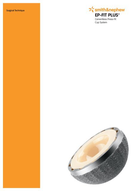
Surgical Technique<br />
*smith&<strong>nephew</strong><br />
<strong>EP</strong>-<strong>FIT</strong> PLUS<br />
Cementless Press-Fit<br />
Cup System
<strong>EP</strong>-<strong>FIT</strong> PLUS<br />
Table of Contents<br />
Foreword ............................................................................... 3<br />
Indications ............................................................................ 4<br />
Contraindications .................................................................. 4<br />
Case Study ............................................................................ 5<br />
Preoperative Planning ........................................................... 5<br />
Surgical Technique ................................................................ 6<br />
Postoperative Treatment ......................................................18<br />
Sterilization ..........................................................................18<br />
References ...........................................................................19<br />
Implants .............................................................................. 20<br />
Instrumentation ................................................................... 26<br />
Nota Bene<br />
The technique description herein is made available to the healthcare professional<br />
to illustrate the authors’ suggested treatment for the uncomplicated procedure.<br />
In the final analysis, the preferred treatment is that which addresses the needs of<br />
the patient.<br />
1
Foreword<br />
Shells conceived on the basis of the press-fit principle offer a number of advantages for total<br />
hip replacement, including ease of manipulation and a minimum degree of bone resection.<br />
In an acetabulum that is not deformed, the implantation of a hemispherical press-fit shell<br />
without oversizing results in a large percentage of the mechanical load being borne by the<br />
central region of the acetabulum. Moreover, the peripheral ring – especially its lower section –<br />
will in part remain free of loading. For this reason hemispherical shells often have a limited<br />
stability. Additional measures to improve stability, for instance the use of screws or mandrels<br />
and/or the use of shells with oversizing (Lachiewicz et al., 1989), can introduce other problems.<br />
In contrast, a hemispherical press-fit shell will bring greater stability in a patient with protrusio<br />
acetabuli. Here, the mechanical loading is primarily on the peripheral zone (Adler et<br />
al., 1992). It is therefore a logical step to optimize the intrinsic stability of the press-fit<br />
shell by reproducing the protrusio situation.<br />
We have therefore developed a shell that is not spherical throughout, with a patented triple<br />
radius profile and which has proven itself over years of use of the <strong>EP</strong>F-PLUS‚ and PLUS-<strong>FIT</strong><br />
acetabular cups. <strong>EP</strong>-<strong>FIT</strong> PLUS is the latest generation of both these cup systems with direct<br />
anchorage for hard articulating surfaces and with a greater surface roughness.<br />
After implantation of the shell, the Triple Radius Profile results in a gap of approximately 2 mm<br />
between the roof of the shell and the hemispherical reamed acetabulum. The actual dimensions<br />
of the gap will vary, however, depending on the quality and elasticity of the bone. This<br />
results in a close contact in the peripheral zone of the shell and a relatively low contact in<br />
the pole region, yielding a favorable prestressing of the wall of the acetabulum. These stress<br />
gradients, declining from the rim towards the dome of the acetabulum, result in a large percentage<br />
of the mechanical loading being transferred to the wall of the acetabulum. This is in<br />
contrast to oversized hemispherical cups, where only a narrow area along the acetabular rim<br />
is subject to loading, and so may result in overloading of the bone in this area.<br />
In summary, the <strong>EP</strong>-<strong>FIT</strong> PLUS system has the advantage of reducing the risk of fracture of<br />
the acetabulum during implantation, whilst maintaining excellent primary stability through<br />
connection to bone over a large area along the wall of the acetabulum.<br />
3
Indications<br />
• All forms of osteoarthritis.<br />
• Progressive loss of function of the hip joint as a result of a degenerative posttraumatic<br />
or inflammatory/rheumatic destruction of the joint.<br />
• Femoral head necrosis.<br />
• Proximal femoral fractures (especially femoral neck).<br />
• Status following earlier operations such as osteosynthesis, intertrochanteric osteotomies,<br />
arthrodesis or failed joint replacement.<br />
Contraindications<br />
• Acute or chronic infections, local or systemic.<br />
• Severe damage to muscles, nerves or vessels that are a risk to the affected extremity.<br />
• Severe bone defects or poor bone quality, endangering the stability of the implant.<br />
• Associated disorders that could interfere with the functioning of the implant.<br />
Remark<br />
• Using hard-hard pairings, it is imperative to follow the specifications in the particular<br />
chapters.<br />
• The above-mentioned indications and contraindications apply for both<br />
primary interventions and revisions.<br />
• If a revision is performed then preferably an oversized implant should be chosen.<br />
Multihole cups can be used for difficult cases.<br />
4
Case Study<br />
Preoperative<br />
Postoperative<br />
Female patient with dysplastic hip with OA. <strong>EP</strong>-<strong>FIT</strong> PLUS shell with SL-PLUS stem<br />
in a female patient with dysplastic hip<br />
with OA. Restoration of leg length.<br />
Preoperative Planning<br />
The surgeon uses the radiographic template (15% enlarged) to plan<br />
• The intended size of the implant.<br />
• The ideal position of the shell in relation to the acetabular teardrop figure.<br />
Note<br />
Exact determination of the size of a shell preoperatively using radiographic templates is only<br />
possible to a certain degree.<br />
In general, the removed femoral head gives a good indication of the size of the acetabular<br />
cup. With a normal acetabulum, the definitive size of the shell is 4–6 mm larger than the<br />
anteroposterior diameter of the removed femoral head.<br />
The correct shell size is finally judged on the basis of the definitive reamer size/the correct<br />
trial shell.<br />
5
Surgical Technique<br />
Note<br />
Users of minimally invasive surgical techniques, please work through the following surgical<br />
instructions additionally: posterolateral approach (Lit. No. 1426); anterolateral approach<br />
(Lit. No. 1483); anterior approach (Lit. No. 1494).<br />
Position of patient and approach<br />
Surgery is performed with the patient in an<br />
extended supine or lateral position.<br />
Surgical approach – lateral or dorsolateral –<br />
is determined on the basis of the patient<br />
data established in advance and preference<br />
of the surgeon.<br />
Removal of the femoral head<br />
An osteotomy of the femoral neck is performed<br />
in accordance with the preoperative<br />
planning for the corresponding stem system.<br />
Preparation of the acetabulum<br />
The joint capsule is opened and sufficiently<br />
resected, fully if necessary.<br />
The acetabulum is exposed to allow a good<br />
view and sufficient room for reaming instruments.<br />
6
Assembly of the reamer<br />
The reamer is placed on the drive shaft using<br />
pressure and turned clockwise until the locking<br />
mechanism snaps in.<br />
Reaming of the acetabulum<br />
The acetabulum is reamed using a spherical<br />
original Smith & Nephew Orthopaedics AG<br />
reamer with increasing diameter until the<br />
cartilage layer is fully removed and the subchondral<br />
bone bleeds uniformly.<br />
Note<br />
It is recommended to begin with a reamer size equal to or 2 mm smaller than the head size<br />
and that reaming is continued down to the base of the fovea acetabuli (teardrop figure).<br />
As much hard sclerotic bone as possible should be removed from the pole region, but<br />
retained in the peripheral zone. It may be advisable to choose a reamer that is in relation<br />
to the cup size 1 mm larger to avoid fissures and ensure optimal seating.<br />
Excessive reaming of the periphery should at all times be avoided as this would result in<br />
a level of bone loss, especially at the anterior and posterior columns of the acetabulum, that<br />
is too high.<br />
The bone slurry that remains in the last reamer can be used to fill in the gap between the<br />
acetabulum and the implant later on.<br />
Reamers with 1 mm increments are available (see page 37).<br />
7
Determination of the implant size using<br />
the trial shell<br />
Screw the trial shell onto the shell inserter<br />
(130707).<br />
2<br />
1<br />
An alignment guide (130728) may be used<br />
for orientation purposes relative to the cup<br />
position. The assembled alignment guide is<br />
mounted on the shell inserter with the trial<br />
shell.<br />
10°–20°<br />
The aim is an anteversion of 10° and an inclination<br />
of 45°. Align the shell inserter in such<br />
a way that rod (1) is perpendicular to the coronal<br />
plane and rod (2) is perpendicular to<br />
the sagittal plane of the patient. If the patient<br />
is lying in the supine position (see illustration,<br />
here: using the example of a right hip), the<br />
long edge of the table can serve as an orientation<br />
guide.<br />
The trial shell is placed in the reamed acetabulum by exerting pressure on the shell inserter<br />
(but without using an impacting tool).<br />
Verification of correct seating in the acetabulum. After removal of the shell inserter the cup<br />
position and depth can be checked. The trial shell is then removed with the shell inserter<br />
screwed back in.<br />
Note<br />
In contrast to the original implants the trial shells are not oversized. If the desired degree<br />
of stability is not attained, then the depth of the bone bed has to be increased (see “Reaming<br />
of the acetabulum”) or the next largest size of trial shell chosen.<br />
8
Implantation of the titanium shell with<br />
trial shell inserter<br />
Bone slurry from the last reaming procedure<br />
can be uniformly distributed in the acetabulum<br />
to compensate for possible gaps.<br />
Mount the shell, of predetermined size, on<br />
the shell inserter (130707).<br />
If necessary, mount the alignment guide<br />
(130728) on the shell inserter.<br />
10°–20°<br />
Position the cup shell in the acetabulum and<br />
align the shell inserter as described in<br />
“Determination of the implant size using the<br />
trial shell”.<br />
The inclination should ideally be 40–50º and<br />
anteversion 10–20º to achieve optimum results.<br />
Final acetabular component orientation<br />
must also consider the position of the femoral<br />
implant, the stability and degree of bone coverage<br />
as well as correct softtissue tensioning,<br />
to achieve the optimal result for each patient.<br />
Any inclination of the shell greater than 50º<br />
must be avoided because of possible impingement<br />
and/or a tendency towards dislocation.<br />
It may be advantageous to use a reliable<br />
navigation system to position the cup as this<br />
would considerably improve the accuracy of<br />
positioning.<br />
If no screws are used, the cup should be<br />
orient ed with screw holes inferiorly. The implant<br />
is inserted into the acetabulum by<br />
impaction with the shell inserter and the<br />
impaction/extraction hammer (130705).<br />
Note<br />
The information on the use of ceramic, metal<br />
and PE inserts must be followed without fail<br />
(see pages 12 to 18).<br />
9
Implantation of the titanium shell using<br />
the shell inserter (US version)<br />
The shell inserter (130987) can be used<br />
instead of the trial shell inserter.<br />
Verification of position in the acetabulum<br />
The distance (1–2 mm) between the implant<br />
and the acetabulum is measured using<br />
the depth gauge for shell (130731) through<br />
the apex hole.<br />
Note<br />
Additional fixation of the <strong>EP</strong>-<strong>FIT</strong> PLUS press-fit<br />
shell by screws is not routinely necessary,<br />
but may be required routinely in certain circumstances.<br />
Fixation of the shell with screws<br />
The procedure is the same as for “Implantation<br />
of the titanium shell using the shell inserter”<br />
above, but the screw holes should be aligned<br />
in a superolateral position upon insertion of<br />
the shell.<br />
Drill the intended holes using the drill guide<br />
(130847) and flexible drill shaft (130490).<br />
Insert the screws into the pelvis with the screwdriver<br />
(130710). An anterior or central position<br />
of the screws must at all times be avoided as<br />
this could result in damage to the large pelvic<br />
vessels and nerves.<br />
Note<br />
Only Smith&Nephew Orthopaedics cancellous<br />
bone screws (25281–25286) with a low<br />
head profile are to be used.<br />
10
Optionally: trial reduction using trial<br />
insert (standard 130826–130839/hooded<br />
130850–130857)<br />
Inner section<br />
The trial stem is inserted in the femur after<br />
the femur has been prepared (see cor respond<br />
ing surgical procedure).<br />
Outer section<br />
Disassemble the inserter (130818).<br />
Screw the corresponding size of trial insert<br />
(standard and hooded) into the inner section<br />
of the seating instrument.<br />
Insert the trial insert into the implanted shell.<br />
Unscrew the inner part of the inserter. Check<br />
the seating of the insert in the shell, reduce<br />
and manipulate.<br />
Check the correct positioning of the PE insert<br />
within the shell.<br />
Screw the internal part of the seating instrument<br />
back into the trial insert, then loosen<br />
and remove it through a gentle tilting action.<br />
Thoroughly rinse the implanted shell and carefully remove the bone debris.<br />
11
Placement of the standard polyethylene<br />
insert using the inserter/impactor<br />
To position the polyethylene insert, it is<br />
recommended to use the inserter/impactor<br />
(130818).<br />
The inserter/impactor must be reassembled<br />
to do so.<br />
Screw the adapter for the PE insert and the<br />
impactor head onto the inserter/impactor.<br />
Retract the internal section of the inserter/<br />
impactor and mount the PE insert on the<br />
three nipples.<br />
Important<br />
The Rexpol inserts, diameter 36 mm, Art.<br />
No. 11000310–311, are not compatible with<br />
the positioning and striking device and require<br />
the Octoplus, Art. No. 1150126, positioning<br />
device or can be inserted manually.<br />
Insert the PE in the shell by impacting the<br />
inner section of the inserter/impactor.<br />
Optionally<br />
Check the fit of the PE insert in the shell using<br />
a raspatory.<br />
Note<br />
The PE insert must not be reused.<br />
Rim osteophytes must be carefully removed<br />
to prevent anterior or lateral impingement,<br />
tendencies to dislocation or restriction of<br />
movement.<br />
12
Insertion of the hooded polyethylene insert using the inserter/impactor<br />
It is recommended to insert the hooded polyethylene insert using the inserter/impactor<br />
(130818).<br />
The procedure for the hooded polyethylene insert and the inserting device is analogous to<br />
the description under “Placement of the standard polyethylene insert using the inserter/<br />
impactor”.<br />
Note<br />
The position of the shoulder of the hooded PE inserts can be changed in 30º increments.<br />
Use of the BIOLOX ® forte/delta ceramic insert<br />
Indications and contraindications<br />
The same indications and contraindications apply to the use of the BIOLOX ® forte/delta cup<br />
inserts as for total hip arthroplasty with other articulating surfaces.<br />
The following additional contraindications apply to ceramic inserts:<br />
• The inclination should not be substantially above or below the range 40–50º.<br />
• The anteversion must not be above or below the range 10–20º.<br />
• If the angle of inclination is below 30º or above 50º BIOLOX ® forte/delta inserts must not be<br />
used. Smith&Nephew Orthopaedics standard and hooded PE inserts are available<br />
for such cases.<br />
• Ceramic cup inserts should similarly not be used for cups in a retroversion mode.<br />
• Risk of impingement should at all times be avoided.<br />
Implantation<br />
A trial insert should be used before a ceramic insert is implanted. Trial heads of the<br />
intended diameter must then be used to ensure an adequate range of motion (ROM) in all<br />
directions and to check the stability of the joint. The artificial joint must not dislocate in<br />
the course of movement or subluxate through impingement of the implant components or<br />
soft tissue.<br />
The alignment guide (130728) should always be used with BIOLOX ® forte/delta ceramic inserts<br />
in order to obtain the necessary level of accuracy.<br />
It is advisable to use computer-assisted navigation systems intraoperatively for documentation<br />
and verification of the implant position and to get exact information on the ROM.<br />
13
Placement of the ceramic insert<br />
The procedure for the trial insert is the same<br />
as described under “Optionally: trial reduction<br />
using trial insert”.<br />
Before insertion it must be ensured that the<br />
inner surface of the metal shell is dry and<br />
free of any debris.<br />
Remove the BIOLOX ® forte ceramic insert<br />
with the premounted CeraLock ® insertion aid<br />
from its packaging. Remove the transparent<br />
Plexiglas triggering protection and dispose<br />
of it.<br />
Place the CeraLock ® insertion aid on the front<br />
face of the metal shell so that all 3 arms lie<br />
on the edge and the BIOLOX ® forte ceramic<br />
insert cannot tilt.<br />
Exert force on the CeraLock ® plateau and<br />
press the BIOLOX ® forte ceramic insert home<br />
into the shell.<br />
The instrument will have now released the<br />
BIOLOX ® forte insert. Remove the CeraLock ®<br />
insertion aid and dispose of it. It is intended<br />
for single usage only and must not be resterilized.<br />
The correct position of the insert in the metal<br />
shell must be checked. Using the tip of the<br />
fingers, touch the 2 front faces of the insert<br />
and metal shell. If the position of the insert<br />
over its entire circumference is level to the<br />
metal edge, then it is correctly positioned in<br />
the shell.<br />
14
Note<br />
To ensure that the BIOLOX ® forte ceramic insert is inserted correctly, it is supplied with a<br />
premounted CeraLock ® insertion aid.<br />
If the patients anatomy does not allow or limit the use of the CeraLock ® to a certain degree,<br />
the ceramic insert can be carefully placed in the cup by hand or with help of the Impactor<br />
for Insert Octoplus (1150126) and pressed home.<br />
Prevention of fracture of a ceramic component<br />
If a ceramic component damage is discovered intraoperatively or a damage is suspected for<br />
good reasons, a ceramic insert must not be used. If already implanted, it must be removed.<br />
A new ceramic inlay must only be used if the internal cone of the shell is free of damage.<br />
Revision involving a broken ceramic insert<br />
In case of acetabular cup revision in which a broken conically fixed ceramic insert is<br />
removed a ceramic insert must not be used again. The cone of the cup may have been<br />
damaged during the reoperation and would then no longer satisfy the requirements<br />
placed on plug connections for conically fixed ceramic inserts. The risk of a fracture is<br />
above average.<br />
A polyethylene insert should be used as an alternative.<br />
Revision of a broken ceramic femoral head<br />
On a femoral prosthesis left in situ after revision of a ceramic femoral head, Smith&Nephew<br />
Orthopaedics recommends the use of a BIOLOX ® OPTION (material: BIOLOX ® delta) femoral<br />
head with metal sleeve (material: TiAl6V4) to be inserted. The BIOLOX ® OPTION system can<br />
be used with any acetabular insert of the BIOLOX ® family as well as with Smith&Nephew<br />
Orthopaedics Polyethylen/Rexpol inserts.<br />
If both components (ball head and insert) are made of ceramic, in case of revision following<br />
a fracture of one of the two components both the insert and the ball head have to be<br />
replaced.<br />
15
Use of the PLUSMET metal insert<br />
Indications and contraindications<br />
Basically the same indications, contraindications and recommendations applying for THR<br />
with other articulating surfaces, also apply for PLUSMET metal inserts.<br />
The following additional contraindications have to be considered for metal inserts:<br />
• Patients with chronic renal failure, renal insufficiency or on dialysis.<br />
• Patients with known allergies of any kind or occupational exposure to cobalt,<br />
Chrome or molybdenum.<br />
• If angle of inclination is below 30º or above 50º, the PLUSMET metal insert<br />
must not be used.<br />
• If angle of anteversion underruns 10º or exeeds 20º, the PLUSMET metal insert must not<br />
be used. Smith&Nephew Orthopaedics standard and hooded PE inserts are available<br />
for such cases.<br />
• If a stable reduction cannot be achieved.<br />
• If cup is positioned in a retroversion mode.<br />
Risk of impingement should at all times be avoided.<br />
Implantation<br />
A trial insert should be used before a metal insert is implanted. Trial heads of the intended<br />
diameter must then be used to ensure an adequate range of motion (ROM) in all directions<br />
of movement and to check the stability of the joint. The artificial joint must not dislocate in the<br />
course of movement or subluxate through impingement of the implant components or soft<br />
tissue. Pressure of the neck of the prosthesis at the edge of the metal insert may cause point<br />
loads that increase the risk of abrasion.<br />
The alignment guide (130728) should always be used with PLUSMET metal inserts in order to<br />
obtain the necessary level of accuracy.<br />
It is advisable to use computer-assisted navigation systems intraoperatively for documentation<br />
and verification of the implant position, and to get exact information on the ROM.<br />
16
Placement of the metal insert (ME)<br />
Proceed with the trial insert as described in<br />
“Optionally: trial reduction using trial insert”.<br />
Before insertion it must be ensured that the<br />
internal surface of the metal shell is dry and<br />
free of any contamination.<br />
Screw the adapter for ME-inserts (130989–<br />
130993) and the impactor head onto the<br />
inserter/impactor.<br />
Attach the implant onto the adapter.<br />
Place the 3 arms of the adapter on the front<br />
face of the metal shell so that the PLUSMET<br />
metal insert is not tilting.<br />
Insert it into the shell by gently hitting the<br />
inserter/impactor.<br />
Note<br />
To impact the metal/insert only the above<br />
described adapter respectively inserter/<br />
impactor must be used.<br />
17
Revision of the metal/ceramic insert<br />
Screw the extraction instrument for metal/<br />
ceramic inserts onto the inserter/impactor<br />
(130818).<br />
Position the extraction instrument on the<br />
edge of the metal/ceramic insert with care.<br />
Fit the 3 tips into the lateral recess in the<br />
shell – they are correctly positioned when<br />
lateral torsion is not possible.<br />
Release the metal/ceramic insert by impaction<br />
of the inserter/impactor and remove it.<br />
Postoperative Treatment<br />
The treatment of the patient after surgery will depend on several factors (in particular the<br />
surgical approach, the stem prosthesis used and any attendant diseases). If the patient has<br />
a good bone quality and the primary implantation of both prosthesic components is stable,<br />
then it is recommended that the patient use walking aids for 6–12 weeks after surgery.<br />
However, the exact degree of walking assistance required will have to be decided by the<br />
physician for each individual patient.<br />
Sterilization<br />
Implants<br />
All the implants described in this Surgical Technique are sterile when they are delivered by<br />
the manufacturer. Resterilization is not allowed.<br />
Instruments<br />
System components and instruments are not sterile when they are delivered. Before use they<br />
must be cleaned by the usual methods in accordance with internal hospital regulations and<br />
sterilized in an autoclave in accordance with the legal regulations and guidelines applicable<br />
in the relevant country. (For detailed information please refer to leaflet Lit. No. 1363.)<br />
The correct settings are given in the instructions for use issued by the autoclave manufacturer.<br />
Instrument manufacturers and dealers accept no responsibility for sterilization of products<br />
by the customer.<br />
18
References<br />
Zwartelé RE, Brand R, Doets HC<br />
Increased risk of dislocation after primary total hip arthroplasty in inflammatory arthritis –<br />
prospective observational study of 410 hips.<br />
Acta Orthop Scand, 2004; 12<br />
Adler E, Stuchin A, Kummer FJ<br />
Stability of Press-Fit acetabular cup.<br />
J Arthroplasty, 1992; 7:295–301<br />
Doets HC, Olsthoorn PGM, Schmotzer H<br />
Medium-term results with the Enhanced Press-Fit Cup in osteoarthrosis, rheumatoid arthritis<br />
and revision arthroplasty, 2003.<br />
Engh CA, Griffin WL, Marx CL<br />
Cementless acetabular components.<br />
J Bone Joint Surg (Br) 1990; 72B:53–59<br />
Lachiewicz PF, Suh PB, Gilbert JA<br />
In vitro initial fixation of porous-coated acetabular total hip components. A biomechanical<br />
comparative study.<br />
J Arthroplasty, 1989; 4:201–205<br />
Lintner F, Zweymüller K, Brand G<br />
Tissue reactions to titanium endoprostheses.<br />
J Arthroplasty, 1986; Vol. 1, No. 3:183–95<br />
McKenzie JR, Callaghan JJ, Pedersen P, Brown TD<br />
Areas of contact and extent of gaps with implantation of oversized acetabular components<br />
in Total Hip Arthroplasty.<br />
Clin Orthop, 1984; 208:127–136<br />
Snorrason F, Kärrholm PJ<br />
Migration of fully threaded acetabular components.<br />
A roentgen stereo-photogrammetic analysis.<br />
J Bone Joint Surg, 1990; 72B:647–652<br />
19
Implants<br />
Shells<br />
Shell Ti-plasma,<br />
without screw holes<br />
Art. No. Art. No.<br />
PO S&N Size<br />
15300 75003886 40<br />
15301 75003887 42<br />
15302 75003888 44<br />
15303 75003889 46<br />
15304 75003890 48<br />
15305 75003891 50<br />
15306 75003892 52<br />
15307 75003893 54<br />
15308 75003894 56<br />
15309 75003895 58<br />
15310 75003896 60<br />
15311 75003897 62<br />
Shell Ti-plasma with<br />
hydroxyapatite coating,<br />
without screw holes<br />
Art. No. Art. No.<br />
PO S&N Size<br />
15340 75003913 40<br />
15341 75003914 42<br />
15342 75003915 44<br />
15343 75003916 46<br />
15344 75003917 48<br />
15345 75003918 50<br />
15346 75003919 52<br />
15347 75003920 54<br />
15348 75003921 56<br />
15349 75003922 58<br />
15350 75003923 60<br />
15351 75003924 62<br />
Shell Ti-plasma,<br />
with screw holes<br />
Art. No. Art. No. No. of<br />
PO S&N Size holes<br />
15320 75003898 40 2<br />
15321 75003899 42 2<br />
15322 75003900 44 2<br />
15323 75003901 46 2<br />
15324 75003902 48 2<br />
15325 75003903 50 2<br />
15326 75003904 52 2<br />
15327 75003905 54 2<br />
15328 75003906 56 3<br />
15329 75003907 58 3<br />
15330 75003908 60 3<br />
15531 75003909 62 3<br />
15532 75003910 64 3<br />
15333 75003911 66 3<br />
15334 75003912 68 3<br />
Shell Ti-plasma with<br />
hydroxyapatite coating,<br />
with screw holes<br />
Art. No. Art. No. No. of<br />
PO S&N Size holes<br />
15360 75003925 40 2<br />
15361 75003926 42 2<br />
15362 75003927 44 2<br />
15363 75003928 46 2<br />
15364 75003929 48 2<br />
15365 75003930 50 2<br />
15366 75003931 52 2<br />
15367 75003932 54 2<br />
15368 75003933 56 3<br />
15369 75003934 58 3<br />
15370 75003935 60 3<br />
15571 75003936 62 3<br />
15572 75003937 64 3<br />
15373 75003938 66 3<br />
15374 75003939 68 3<br />
20
Shell Ti-plasma, multihole<br />
Art.No. Art. No. Size No. of<br />
PO S&N holes<br />
15410 75003944 56 6<br />
15411 75003945 58 6<br />
15412 75003946 60 6<br />
15413 75003947 62 6<br />
15414 75003948 64 6<br />
15415 75003949 66 6<br />
15416 75003950 68 6<br />
21
Inserts<br />
Note<br />
All cup inserts must only be used in combination with the acetabular cup systems approved<br />
by Smith&Nephew Orthopaedics AG.<br />
PE inserts, standard (1)<br />
Art. No. Art. No.<br />
S&N PO Ø Size<br />
75003956 15462 22 mm 40–44<br />
75003957 15463 22 mm 46<br />
75003958 15464 22 mm 48<br />
75003959 15465 22 mm 50<br />
75003960 15470 28 mm 46<br />
75003961 15471 28 mm 48<br />
75003962 15472 28 mm 50–52<br />
75003963 15473 28 mm 54–56<br />
75003964 15474 28 mm 58–68<br />
75003967 15481 32 mm 50–52<br />
75003968 15482 32 mm 54–56<br />
75003969 15483 32 mm 58–68<br />
PE inserts, hooded, 15° (2)<br />
Art. No. Art. No.<br />
S&N PO Ø Size<br />
75003970 15486 28 mm 46<br />
75003971 15487 28 mm 48<br />
75003972 15488 28 mm 50–52<br />
75003973 15489 28 mm 54–56<br />
75003976 15490 28 mm 58–68<br />
75003977 15491 32 mm 50–52<br />
75003978 15492 32 mm 54–56<br />
75003979 15493 32 mm 58–68<br />
(1)<br />
(2)<br />
REXPOL, standard (3)<br />
Art. No. Art. No.<br />
S&N PO Ø Size<br />
75004001 15570 28 mm 46<br />
75004002 15571 28 mm 48<br />
75004003 15572 28 mm 50–52<br />
75004004 15573 28 mm 54–56<br />
75004005 15574 28 mm 58–68<br />
75004006 15582 32 mm 50–52<br />
75004007 15583 32 mm 54–56<br />
75004008 15584 32 mm 58–68<br />
75000131 11000310 36 mm 54–56<br />
75000132 11000311 36 mm 58–68<br />
REXPOL, hooded 15° (4)<br />
Art. No. Art. No.<br />
S&N PO Ø Size<br />
75003983 15500 28 mm 46<br />
75003984 15501 28 mm 48<br />
75003985 15502 28 mm 50–52<br />
75003986 15503 28 mm 54–56<br />
75003987 15504 28 mm 58–68<br />
75003989 15512 32 mm 50–52<br />
75003990 15513 32 mm 54–56<br />
75003991 15514 32 mm 58–68<br />
(3)<br />
(4)<br />
22
Note<br />
<strong>EP</strong>-<strong>FIT</strong> PLUS metal inserts must only be used with PLUSMET metal ball heads<br />
for metal/metal pairings. Ball heads from other manufacturers must not be used.<br />
Metal inserts, standard<br />
Art. No. Art. No.<br />
S&N PO Ø Size<br />
75003856 15100 28 mm 46<br />
75003857 15101 28 mm 48<br />
75003858 15102 28 mm 50–52<br />
75003859 15103 28 mm 54–56<br />
75003860 15104 28 mm 58–68<br />
Ceramic inserts, BIOLOX ® forte<br />
Art. No. Art. No.<br />
S&N PO Ø Size<br />
75003865 15140 28 mm 46<br />
75003866 15141 28 mm 48<br />
75003867 15142 28 mm 50–52<br />
75003868 15143 28 mm 54–56<br />
75003869 15144 28 mm 58–68<br />
75003870 15149 32 mm 46<br />
75003872 15150 32 mm 48<br />
75003873 15151 32 mm 50–52<br />
75003874 15152 32 mm 54–56<br />
75003875 15153 32 mm 58–68<br />
75007454 66021 44/36 mm 50–52<br />
75007455 66022 48/36 mm 54–56<br />
75007456 66023 52/36 mm 58–68<br />
Ceramic inserts, BIOLOX ® delta<br />
Art. No. Art. No.<br />
S&N PO Ø Size<br />
75001964 11000191 39/32 mm 46<br />
75001965 11000192 41/32 mm 48<br />
75001966 11000193 44/32 mm 50–52<br />
75001967 11000194 48/32 mm 54–56<br />
75001968 11000195 52/32 mm 58–68<br />
75007457 66024 44/36 mm 50–52<br />
75007458 66025 48/36 mm 54–56<br />
75007459 66026 52/36 mm 58–68<br />
Note<br />
Only a combination of BIOLOX ® forte/delta ball heads with cup inserts of BIOLOX ® forte/delta<br />
is permitted. Any of the BIOLOX ® forte/delta family of ball heads may be used with any of<br />
the ceramic inserts from the BIOLOX ® family, provided that the correct head/calotte diameter<br />
is used. Other components that have not been approved by Smith&Nephew Orthopaedics<br />
must not be used. Pairings with 32 mm ball heads or bigger generally improve the range of<br />
motion and thus reduce the risk of impingement and subluxation.<br />
23
Ball heads<br />
Ceramic ball heads, BIOLOX ® forte<br />
Art. No. Art. No.<br />
S&N PO Ø Cone Neck length<br />
75004169 16151 28 mm 12/14 S<br />
75004170 16152 28 mm 12/14 M<br />
75004171 16153 28 mm 12/14 L<br />
75004172 16161 32 mm 12/14 S<br />
75004173 16162 32 mm 12/14 M<br />
75004174 16163 32 mm 12/14 L<br />
75007441 66011 36 mm 12/14 S<br />
75007442 66012 36 mm 12/14 M<br />
75007446 66013 36 mm 12/14 L<br />
Ceramic ball heads, BIOLOX ® delta<br />
Art. No. Art. No.<br />
S&N PO Ø Cone Neck length<br />
75007451 66018 28 mm 12/14 S<br />
75007452 66019 28 mm 12/14 M<br />
75007453 66020 28 mm 12/14 L<br />
75007460 66027 32 mm 12/14 S<br />
75007461 66028 32 mm 12/14 M<br />
75007462 66029 32 mm 12/14 L<br />
75007463 66030 32 mm 12/14 XL<br />
75007448 66015 36 mm 12/14 S<br />
75007449 66016 36 mm 12/14 M<br />
75007450 66017 36 mm 12/14 L<br />
75007447 66014 36 mm 12/14 XL<br />
Metal ball heads, PLUSMET<br />
Art. No. Art. No.<br />
S&N PO Ø Cone Neck length<br />
75004181 16181 28 mm 12/14 S<br />
75004182 16182 28 mm 12/14 M<br />
75004183 16183 28 mm 12/14 L<br />
75004184 16184 28 mm 12/14 XL<br />
75004185 16185 28 mm 12/14 XXL<br />
75011852 16186 28 mm 14/16 S<br />
75011853 16187 28 mm 14/16 M<br />
75011854 16188 28 mm 14/16 L<br />
75011855 16189 28 mm 14/16 XL<br />
75011856 16190 28 mm 14/16 XXL<br />
24
Ceramic ball heads, BIOLOX ® OPTION (for revisions)<br />
Art. No. Art. No.<br />
S&N PO Ø Cone Neck length<br />
75007727 CE3849717693581 28 mm 12/14 S<br />
75007728 CE3849717693582 28 mm 12/14 M<br />
75016564 CE3849717693583 28 mm 12/14 L<br />
75007729 CE3849717693584 28 mm 12/14 XL<br />
75007731 CE3849717694581 32 mm 12/14 S<br />
75007732 CE3849717694582 32 mm 12/14 M<br />
75016565 CE3849717694583 32 mm 12/14 L<br />
75007733 CE3849717694584 32 mm 12/14 XL<br />
75007735 CE3849717696581 36 mm 12/14 S<br />
75007736 CE3849717696582 36 mm 12/14 M<br />
75007738 CE3849717696585 36 mm 12/14 L<br />
75007737 CE3849717696584 36 mm 12/14 XL<br />
Note<br />
Before the BIOLOX ® forte/delta/OPTION, PLUSMET ball head<br />
is placed on the stem it must be ensured that the cone is free<br />
of contaminating particles such as bone fragments, metal or<br />
cement, and that it is not damaged.<br />
Cancellous bone screws (sterile)<br />
Art. No. Art. No.<br />
S&N PO Description Ø Length<br />
75005904 25281 Cancellous bone screw 6,5 mm 20 mm<br />
75005905 25282 Cancellous bone screw 6,5 mm 25 mm<br />
75005906 25283 Cancellous bone screw 6,5 mm 30 mm<br />
75005910 25287 Cancellous bone screw 6,5 mm 35 mm<br />
75005907 25284 Cancellous bone screw 6,5 mm 40 mm<br />
75005911 25288 Cancellous bone screw 6,5 mm 45 mm<br />
75005908 25285 Cancellous bone screw 6,5 mm 50 mm<br />
75005912 25289 Cancellous bone screw 6,5 mm 55 mm<br />
75005909 25286 Cancellous bone screw 6,5 mm 60 mm<br />
CeraLock ® , BIOLOX ® forte, BIOLOX ® OPTION and BIOLOX ® delta are registered<br />
trademarks of CeramTec AG, Germany.<br />
25
Instrumentation<br />
Case 1<br />
1 A Basic Case: Instruments and trial shells<br />
Art. No. Art. No.<br />
S&N PO Description Size<br />
75003499 130994 Basic Case I (without cover)<br />
75003404 130999 Cover for <strong>EP</strong>-<strong>FIT</strong> PLUS case<br />
75003344 130707 Shell Inserter, standard version<br />
75003340 130705 Insertion/Extraction hammer<br />
75003355 130728 Shell alignment guide, standard version<br />
75003357 130731 Depth gauge for shell<br />
75003359 130734 Trial shell 40<br />
75003360 130735 Trial shell 42<br />
75003344 130712 Trial shell 44<br />
75003345 130713 Trial shell 46<br />
75003346 130714 Trial shell 48<br />
75003347 130715 Trial shell 50<br />
75003348 130716 Trial shell 52<br />
75003349 130717 Trial shell 54<br />
75003350 130719 Trial shell 56<br />
75003351 130720 Trial shell 58<br />
75003352 130721 Trial shell 60<br />
75003353 130723 Trial shell 62<br />
75003354 130724 Trial shell 64<br />
75003361 130736 Trial shell 66<br />
75003362 130737 Trial shell 68<br />
75003373 130820 Extraction instrument for metal/ceramic insert to 130818 46<br />
75003363 130794 Extraction instrument for metal/ceramic insert to 130818 48<br />
75003364 130795 Extraction instrument for metal/ceramic insert to 130818 50–52<br />
75003365 130796 Extraction instrument for metal/ceramic insert to 130818 54–56<br />
75003366 130797 Extraction instrument for metal/ceramic insert to 130818 58–68<br />
26
27
1 B Tray: Reamer (2 mm increments) and inserter/impactor for PE inserts<br />
Art. No. Art. No.<br />
S&N PO Description Size<br />
75003501 130996 Tray to Case 130994<br />
75003405 130870 Drive shaft, with Synthes-coupling<br />
75003406 130871 Reamer 40<br />
75003408 130873 Reamer 42<br />
75003410 130875 Reamer 44<br />
75003412 130877 Reamer 46<br />
75003414 130879 Reamer 48<br />
75003416 130881 Reamer 50<br />
75003418 130883 Reamer 52<br />
75003420 130885 Reamer 54<br />
75003422 130887 Reamer 56<br />
75003424 130889 Reamer 58<br />
75003426 130891 Reamer 60<br />
75003428 130893 Reamer 62<br />
75003430 130895 Reamer 64<br />
75003432 130897 Reamer 66<br />
75003434 130899 Reamer 68<br />
75003374 130822 Impactor head 22<br />
75003475 130823 Impactor head 28<br />
75003476 130824 Impactor head 32<br />
75003392 130848 Impactor head 36<br />
75003372 130818 Inserter/Impactor<br />
75003367 130802 Adapter for PE insert, standard, to 130818 40–44<br />
75003368 130803 Adapter for PE insert, standard, to 130818 46–48<br />
75003369 130804 Adapter for PE insert, standard, to 130818 50–68<br />
75003370 130806 Adapter for PE insert, hooded, to 130818 46–48<br />
75003371 130807 Adapter for PE insert, hooded, to 130818 50–68<br />
28
29
Case 2<br />
2 A Basic Case: Trial inserts<br />
Art. No. Art. No.<br />
S&N PO Description Ø Size<br />
75003506 131001 Basic Case II (without cover)<br />
75003504 130999 Cover for <strong>EP</strong>-<strong>FIT</strong> PLUS case<br />
75003494 130989 Adapter for ME insert, standard, to 130818 46<br />
75003495 130990 Adapter for ME insert, standard, to 130818 48<br />
75003496 130991 Adapter for ME insert, standard, to 130818 50–52<br />
75003497 130992 Adapter for ME insert, standard, to 130818 54–56<br />
75003498 130993 Adapter for ME insert, standard, to 130818 58–68<br />
75003377 130826 Trial insert, standard 22 mm 40–44<br />
75003378 130827 Trial insert, standard 22 mm 46<br />
75003379 130828 Trial insert, standard 22 mm 48<br />
75003380 130829 Trial insert, standard 22 mm 50<br />
75003381 130830 Trial insert, standard 28 mm 46<br />
75003382 130831 Trial insert, standard 28 mm 48<br />
75003383 130832 Trial insert, standard 28 mm 50–52<br />
75003384 130833 Trial insert, standard 28 mm 54–56<br />
75003385 130834 Trial insert, standard 28 mm 58–68<br />
75003386 130835 Trial insert, standard 32 mm 46<br />
75003387 130836 Trial insert, standard 32 mm 48<br />
75003388 130837 Trial insert, standard 32 mm 50–52<br />
75003389 130838 Trial insert, standard 32 mm 54–56<br />
75003390 130839 Trial insert, standard 32 mm 58–68<br />
75007443 660121 Trial insert, standard 36 mm 50–52<br />
75007444 660122 Trial insert, standard 36 mm 54–56<br />
75007445 660123 Trial insert, standard 36 mm 58–68<br />
75003394 130850 Trial insert, hooded 28 mm 46<br />
75003395 130851 Trial insert, hooded 28 mm 48<br />
75003396 130852 Trial insert, hooded 28 mm 50–52<br />
75003397 130853 Trial insert, hooded 28 mm 54–56<br />
75003398 130854 Trial insert, hooded 28 mm 58–68<br />
75003399 130855 Trial insert, hooded 32 mm 50–52<br />
75003400 130856 Trial insert, hooded 32 mm 54–56<br />
75003401 130857 Trial insert, hooded 32 mm 58–68<br />
30
31
2 B Tray: Bone screws and accessories<br />
Art. No. Art. No.<br />
S&N PO Description Ø Length<br />
75003500 130995 Tray to Case 131001<br />
75003282 130490 Flexible drill shaft for quick coupling<br />
75003391 130847 Drill guide for screws 3,2 mm<br />
75003342 130708 Depth gauge for screws<br />
75003358 130732 Screw-holding forceps<br />
75003343 130710 Screwdriver, hexagon W 3,5 mm<br />
75003283 130492 Twist drill 3,2 mm 56 mm<br />
75003284 130493 Twist drill 3,2 mm 70 mm<br />
75003285 130496 Cardan screwdriver, hexagon W 3,5 mm<br />
75003507 131002 Container for cancellous bone screws to tray 130995<br />
32
33
Case 3<br />
3 A Basic Case: Instruments and trial shells (identical to 1A)<br />
Art. No. Art. No.<br />
S&N PO Description Size<br />
75003505 131000 Basic Case III (without cover)<br />
75003539 130999 Cover for <strong>EP</strong>-<strong>FIT</strong> PLUS case<br />
75013965 130707 Shell inserter, standard version<br />
75013965 130705 Insertion/Extraction hammer<br />
75013967 130728 Shell alignment guide, standard version<br />
75013968 130731 Depth gauge for shell<br />
75013968 130734 Trial shell 40<br />
75013968 130735 Trial shell 42<br />
75013966 130712 Trial shell 44<br />
75013966 130713 Trial shell 46<br />
75013966 130714 Trial shell 48<br />
75013966 130715 Trial shell 50<br />
75013966 130716 Trial shell 52<br />
75013966 130717 Trial shell 54<br />
75013966 130719 Trial shell 56<br />
75013967 130720 Trial shell 58<br />
75013967 130721 Trial shell 60<br />
75013967 130723 Trial shell 62<br />
75013967 130724 Trial shell 64<br />
75013968 130736 Trial shell 66<br />
75013968 130737 Trial shell 68<br />
75013975 130820 Extraction instrument for metal/ceramic insert, to 130818 46<br />
75003537 130794 Extraction instrument for metal/ceramic insert, to 130818 48<br />
75003537 130795 Extraction instrument for metal/ceramic insert, to 130818 50–52<br />
75003537 130796 Extraction instrument for metal/ceramic insert, to 130818 54–56<br />
75003537 130797 Extraction instrument for metal/ceramic insert, to 130818 58–68<br />
34
35
3 B Tray: Reamer (1 mm increments) sizes 40–43 and 66–69<br />
Art. No. Art. No.<br />
S&N PO Description Size<br />
75003503 130998 Tray to Case 131000<br />
75003493 130987 Shell Inserter<br />
75003481 130975 Adapter, to 130987 40–44<br />
75003482 130976 Adapter, to 130987 46<br />
75003483 130977 Adapter, to 130987 48<br />
75003484 130978 Adapter, to 130987 50–52<br />
75003485 130979 Adapter, to 130987 54–56<br />
75003486 130980 Adapter, to 130987 58–68<br />
75003432 130897 Reamer 66<br />
75003433 130898 Reamer 67<br />
75003434 130899 Reamer 68<br />
75003435 130900 Reamer 69<br />
75003406 130871 Reamer 40<br />
75003407 130872 Reamer 41<br />
75003408 130873 Reamer 42<br />
75003409 130874 Reamer 43<br />
75003374 130822 Impactor head 22<br />
75003375 130823 Impactor head 28<br />
75003376 130824 Impactor head 32<br />
75003392 130848 Impactor head 36<br />
75003367 130802 Adapter for PE insert, standard, to 130818 40–44<br />
75003368 130803 Adapter for PE insert, standard, to 130818 46–48<br />
75003369 130804 Adapter for PE insert, standard, to 130818 50–68<br />
75003370 130806 Adapter for PE insert, hooded, to 130818 46–48<br />
75003371 130807 Adapter for PE insert, hooded, to 130818 50–68<br />
75003372 130818 Inserter/Impactor<br />
75003402 130858 Shell alignment guide (US version)<br />
36
37
3 C Tray: Reamer (1 mm increments) sizes 44–45<br />
Art. No. Art. No.<br />
S&N PO Description Size<br />
75003502 130997 Tray to Case 131000<br />
75003405 130870 Drive shaft<br />
75003410 130875 Reamer 44<br />
75003411 130876 Reamer 45<br />
75003412 130877 Reamer 46<br />
75003413 130878 Reamer 47<br />
75003414 130879 Reamer 48<br />
75003415 130880 Reamer 49<br />
75003416 130881 Reamer 50<br />
75003417 130882 Reamer 51<br />
75003418 130883 Reamer 52<br />
75003419 130884 Reamer 53<br />
75003420 130885 Reamer 54<br />
75003421 130886 Reamer 55<br />
75003422 130887 Reamer 56<br />
75003423 130888 Reamer 57<br />
75003424 130889 Reamer 58<br />
75003425 130890 Reamer 59<br />
75003426 130891 Reamer 60<br />
75003427 130892 Reamer 61<br />
75003428 130893 Reamer 62<br />
75003429 130894 Reamer 63<br />
75003430 130895 Reamer 64<br />
75003431 130896 Reamer 65<br />
Note<br />
Case 1 may be replaced by case 3 if a reamer with 1 mm increments is required.<br />
38
39
40<br />
Notes
Manufacturer<br />
Smith & Nephew Orthopaedics AG For further information please contact<br />
Erlenstrasse 4a<br />
our local sales office.<br />
6343 Rotkreuz www.smith-<strong>nephew</strong>.com<br />
Switzerland<br />
Trademark of Smith & Nephew Lit. No. 1258-e Ed. 11/07 EU 300 Ex. 04/08 300 Ex. 11/07 0123