surgical technique
surgical technique
surgical technique

Create successful ePaper yourself
Turn your PDF publications into a flip-book with our unique Google optimized e-Paper software.
Ascension ®<br />
MCP<br />
<strong>surgical</strong> <strong>technique</strong><br />
<strong>surgical</strong> <strong>technique</strong> Ascension ® MCP PyroCarbon Total Joint<br />
WW
1.0<br />
Table of<br />
Contents<br />
2.0 Introduction . . . . . . . . . . . . . . . . . . . . . . . . . . . . 2<br />
3.0 Ascension ® MCP Implants . . . . . . . . . . . . . . . . 2<br />
4.0 Instrumentation for MCP Arthroplasty . . . . . 3<br />
5.0 Pre-Operative Assessment . . . . . . . . . . . . . . . . 4<br />
6.0 Surgical Technique . . . . . . . . . . . . . . . . . . . 5-15<br />
6.1 Initial Incision and<br />
Joint Exposure . . . . . . . . . . . . . . . . . . 5<br />
6.2 Opening the Metacarpal<br />
Medullary Canal. . . . . . . . . . . . . . . . . 5<br />
6.3 Establishing Metacarpal<br />
Medullary Canal Alignment . . . . . . . 6<br />
6.4 Metacarpal Osteotomy . . . . . . . . . . 6-7<br />
6.5 Opening the Phalangeal<br />
Medullary Canal. . . . . . . . . . . . . . . . . 8<br />
6.6 Establishing Phalangeal<br />
Medullary Canal Alignment . . . . . . . 8<br />
6.7 Phalangeal Osteotomy . . . . . . . . . . . . 9<br />
6.8 Phalangeal Medullary<br />
Canal Broaching. . . . . . . . . . . . . . . . 10<br />
6.9 Metacarpal Medullary<br />
Canal Broaching. . . . . . . . . . . . . . . . 11<br />
6.10 Trial Insertion and Reduction . . . . . 12<br />
6.11 Removal of Trial Components . . . . . 13<br />
6.12 Implantation of<br />
Ascension ® MCP Components. . . . . 13<br />
6.13 Final Reduction and<br />
Soft Tissue Closure . . . . . . . . . . . . . . 14<br />
6.14 Post-Operative Dressing . . . . . . . . . . 14<br />
6.15 Implant Removal . . . . . . . . . . . . . . . 15<br />
7.0 Appendix – MCP Instrument Set<br />
and Part Numbers . . . . . . . . . . . . . . . . . . . . . 16
2.0 Introduction<br />
This manual describes the sequence of <strong>technique</strong>s<br />
and instruments used to implant the Ascension ® MCP<br />
(FIGURE 2.1). The <strong>surgical</strong> <strong>technique</strong> and instruments<br />
have been developed to assist in achieving correct<br />
<strong>surgical</strong> placement. Successful use of this implant depends<br />
on the proper patient selection, <strong>surgical</strong> <strong>technique</strong>, and<br />
post-operative therapy. The post-operative rehabilitation<br />
protocol is described in a separate brochure, but is<br />
essential to a good <strong>surgical</strong> outcome.<br />
If questions arise, or a Post-Operative Therapy Protocol<br />
brochure is needed, please contact Ascension<br />
Orthopedics at 877-370-5001 (toll-free) or e-mail<br />
us at customerservice@ascensionortho.com.<br />
Metacarpal Component<br />
(PROXIMAL)<br />
FIGURE 2.1 – Ascension ® MCP<br />
Phalangeal Component<br />
(DISTAL)<br />
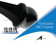
3.0 Ascension® MCP<br />
Implants<br />
<strong>surgical</strong> <strong>technique</strong> Ascension ® MCP<br />
The Ascension ® MCP is a metacarpophalangeal<br />
total joint replacement consisting of separate proximal Phalangeal Components<br />
(DISTAL)<br />
and distal components. The proximal component<br />
30<br />
replaces the metacarpal head and the distal component<br />
40<br />
replaces the base of the proximal phalanx. It is<br />
available in five sizes (FIGURE 3.1). Intramedullary<br />
20<br />
stems stabilize both components. Components are<br />
implanted using a press-fit <strong>technique</strong>. Guided<br />
osteotomies are made first to the metacarpal head<br />
10<br />
and then the phalangeal base. Next the medullary<br />
canals are progressively broached to the desired size.<br />
The phalanx is broached first because it generally<br />
determines the sizing of the implant. Trial implants<br />
are then inserted, and the joint is reduced. Once<br />
the trial reduction is satisfactory, the trial implants<br />
Metacarpal Components<br />
(PROXIMAL)<br />
are removed, and the final implants are impacted<br />
into place. SIZE CATALOG NUMBER<br />
10 MCP-100-10<br />
20 MCP-100-20<br />
30 MCP-100-30<br />
40 MCP-100-40<br />
50 MCP-100-50<br />
FIGURE 3.1<br />
50<br />
2
4.0<br />
Instrumentation for<br />
MCP Arthroplasty<br />
FIGURE 4.1 — INS-100-00<br />
Ascension ® MCP<br />
Instrument Set<br />
MCP Distal Osteotomy Guide<br />
(PHALANGEAL)<br />
MCP Trials – Sizes 10-50<br />
MCP Distal Impactor<br />
(PHALANGEAL)<br />
MCP Distal Broaches<br />
Sizes 10-50<br />
(PHALANGEAL)<br />
Alignment Guide<br />
MCP Implant Extractor<br />
MCP Trial Extractor<br />
Starter Awl<br />
Alignment Awl<br />
MCP Proximal Broaches<br />
Sizes 10-50<br />
(METACARPAL)<br />
MCP Proximal Impactor<br />
(METACARPAL)<br />
MCP Proximal Osteotomy Guide<br />
(METACARPAL)<br />
FIGURE 4.2 — Alignment Awl, Alignment<br />
Guide and Osteotomy Guides<br />
AWL-100-00<br />
Alignment Awl<br />
OSG-100-00D<br />
MCP Distal Osteotomy Guide<br />
(PHALANGEAL)<br />
ALG-100-00<br />
Alignment Guide<br />
OSG-100-00P<br />
MCP Proximal Osteotomy Guide<br />
(METACARPAL)<br />
3<strong>surgical</strong> <strong>technique</strong> Ascension® MCP
5.0 Pre-Operative<br />
Assessment<br />
Ascension ® MCP implant arthroplasty is appropriate<br />
for use in patients with osteo- and posttraumatic<br />
arthritis with nearly normal soft tissue envelopes.<br />
In patients with rheumatoid arthritis, soft tissue<br />
imbalance may be more severe, and the surgeon<br />
must determine that correction of volar subluxation<br />
deformities and ulnar deviation deformities can<br />
be achieved with standard MCP reconstruction<br />
<strong>technique</strong>s. Standard AP, lateral and oblique x-rays<br />
can be used to template the size of the implant likely<br />
to be required at surgery (FIGURE 5.1). The templates<br />
are 3% magnified approximating the standard<br />
magnification of most routine x-ray <strong>technique</strong>s.<br />
Note that digital (electronic) x-ray magnification<br />
may be quite variable and the surgeon should consult<br />
with the x-ray technician/radiologist to assure<br />
usefulness of the templates.<br />
FIGURE 5.1 — X-ray Templates<br />
The largest Ascension ® MCP (Size 50) implant should<br />
be large enough for the largest hand (FIGURE 3.1).<br />
The smallest implant (Size 10) however, may be<br />
too large in patients with juvenile rheumatoid<br />
arthritis and alternative treatment options should<br />
be considered in these cases. In patients with severe<br />
intercarpal supination and radial deviation of the<br />
wrist, ulnar deviation of the digits may not be correctable<br />
with soft tissue surgery, and in these instances,<br />
it is recommended that corrective wrist surgery be<br />
performed first at a separate setting.<br />
<strong>surgical</strong> <strong>technique</strong> Ascension ® MCP<br />
4
6.0 Surgical<br />
Technique<br />
6.1 Initial Incision and<br />
Joint Exposure<br />
For single joint involvement:<br />
A longitudinal incision is made over the dorsum of<br />
the metacarpophalangeal (MCP) joint (FIGURE 6.1.1).<br />
Incision for single joint<br />
involvement<br />
Incision for multiple joint<br />
involvement<br />
FIGURE 6.1.1<br />
For multiple joint involvement:<br />
A curving transverse incision across the dorsum<br />
of the MCPs is recommended when multiple joints<br />
are involved (FIGURE 6.1.1). The extensor hood is<br />
incised on the radial side of the central tendon or<br />
through its center if no dislocation/subluxation of the<br />
tendon is present. Attempts are made to dissect the<br />
extensor tendon free from the joint capsule radially<br />
and ulnarly. This may not be possible in advanced<br />
disease. The capsule is split longitudinally and<br />
dissected to expose the joint, preserving the capsule<br />
as much as possible for later repair. The dissection<br />
should be continued so that the dorsal base of the<br />
proximal phalanx and the metacarpal head with<br />
the collateral ligament origins are visualized.<br />
FIGURE 6.2.1<br />
6.2 Opening the Metacarpal<br />
Medullary Canal<br />
The starter awl is used to make the initial puncture<br />
of the metacarpal head (FIGURE 6.2.1). This puncture<br />
should be placed volar to the dorsal surface of the<br />
metacarpal head a distance one-third the sagittal<br />
height of the head and centered across the width<br />
of the head (FIGURE 6.2.2). The resulting puncture<br />
should be aligned with the long axis of the<br />
metacarpal’s medullary canal.<br />
1/3<br />
FIGURE 6.2.2<br />
5<strong>surgical</strong> <strong>technique</strong> Ascension® MCP
6.3 Establishing Metacarpal<br />
Medullary Canal Alignment<br />
Attach the alignment guide to the alignment awl,<br />
(FIGURE 4.2) insert the alignment awl into the puncture<br />
(FIGURE 6.3.1) and advance it into the medullary canal<br />
one-half to two-thirds the length of the metacarpal<br />
(FIGURE 6.3.2). With the alignment guide mounted on<br />
the alignment awl it is possible to sight between the<br />
guide rod and the dorsal surface of the metacarpal.<br />
The alignment guide should be parallel to the dorsal<br />
surface of the metacarpal and in line with the long<br />
axis of the bone.<br />
FIGURE 6.3.1<br />
6.4 Metacarpal<br />
Osteotomy<br />
The metacarpal head osteotomy is made in two steps:<br />
FIGURE 6.3.2<br />
Step 1:<br />
A guided partial osteotomy is made using<br />
the proximal osteotomy guide mounted<br />
on the alignment awl.<br />
Step 2: The osteotomy is completed free hand<br />
by following the previously established<br />
osteotomy plane.<br />
<strong>surgical</strong> <strong>technique</strong> Ascension ® MCP<br />
Attach the proximal osteotomy guide (FIGURE 4.2) on<br />
the alignment awl along the previously established<br />
medullary axis. The osteotomy guide is advanced<br />
until the cutting plane of the guide is positioned<br />
1.0 to 2.0 mm distal to the dorsal attachments of the<br />
collateral ligaments. The osteotomy guide provides<br />
a 27.5° distal tilt from vertical (FIGURE 6.4.1).<br />
Rotational alignment of the osteotomy guide is<br />
achieved when the volar surface of the guide is<br />
parallel to the dorsal surface of the metacarpal bone.<br />
27.5°<br />
FIGURE 6.4.1<br />
6
6.4 Metacarpal Osteotomy<br />
CONTINUED<br />
NOTE:<br />
It is strongly recommended that, initially, a conservative<br />
osteotomy be made and then altered later. This allows<br />
for joint space adjustment during the fitting of the trial<br />
implants (see section 6.10). A conservative osteotomy is<br />
considered generally to be at least 1.5mm distal to the<br />
dorsal attachments of the collateral ligaments.<br />
FIGURE 6.4.2<br />
SPECIAL THIN BLADE REQUIREMENTS:<br />
It is strongly recommended when performing the<br />
osteotomy that a small oscillating saw blade be used<br />
(7mm x 29.5mm x 0.4mm).<br />
With the metacarpal cutting guide held steady the<br />
cut is performed by passing the saw blade of a small<br />
sagittal saw through the blade slot of the cutting<br />
guide (FIGURE 6.4.2). The collateral ligaments’<br />
integrity should be retained as far as possible.<br />
Because of the presence of the intramedullary rod of<br />
the alignment awl only a partial (dorsal) osteotomy<br />
can be performed with the cutting guide in place.<br />
FIGURE 6.4.3<br />
Completing the Osteotomy<br />
Remove the alignment awl and complete the<br />
osteotomy by following the plane established by<br />
the guided cut (FIGURE 6.4.3).<br />
7<strong>surgical</strong> <strong>technique</strong> Ascension® MCP
6.5 Opening the Phalangeal<br />
Medullary Canal<br />
FIGURE 6.5.1<br />
With the joint flexed, the starter awl is used to make<br />
the initial puncture of the proximal phalangeal base<br />
(FIGURE 6.5.1).<br />
CAUTION:<br />
The joint must be flexed to avoid damage (by<br />
impingement) to the dorsal edge of the metacarpal<br />
osteotomy (FIGURE 6.5.2).<br />
Avoid<br />
impingement<br />
FIGURE 6.5.2<br />
This puncture should be placed volar to the dorsal<br />
surface of the proximal phalanx a distance one-third<br />
the sagittal height of the proximal phalangeal base and<br />
centered across the width of the base. The resulting<br />
puncture should be aligned with the long axis of the<br />
proximal phalangeal’s medullary canal (FIGURE 6.5.2).<br />
1/3<br />
6.6 Establishing Phalangeal<br />
Medullary Canal Alignment<br />
With the joint flexed, insert the alignment awl in the<br />
puncture and advance it into the phalangeal medullary<br />
canal one-half to two-thirds the length of the phalanx<br />
(FIGURE 6.6.1).<br />
FIGURE 6.6.1<br />
CAUTION:<br />
The joint must be flexed to avoid damage (by<br />
impingement) to the dorsal edge of the metacarpal<br />
osteotomy (FIGURE 6.6.2).<br />
<strong>surgical</strong> <strong>technique</strong> Ascension ® MCP<br />
With the alignment guide mounted on the alignment<br />
awl it is possible to sight between the guide rod and<br />
the dorsal surface of the phalanx. The alignment guide<br />
should be parallel to the dorsal surface of the phalanx<br />
and in line with the long axis of the bone.<br />
Avoid<br />
impingement<br />
FIGURE 6.6.2<br />
8
6.7 Phalangeal<br />
Osteotomy<br />
The phalangeal base osteotomy is made in two steps:<br />
FIGURE 6.7.1<br />
Step 1:<br />
Step 2:<br />
A guided partial osteotomy is made using<br />
the distal osteotomy guide mounted on the<br />
alignment awl.<br />
The osteotomy is completed free hand by following<br />
the previously established osteotomy plane.<br />
5°<br />
CAUTION:<br />
The joint must be flexed to avoid damage (by<br />
impingement) to the dorsal edge of the metacarpal<br />
osteotomy (FIGURE 6.7.1).<br />
Attach the distal osteotomy guide on the alignment<br />
awl and reinsert the awl along the previously<br />
established medullary axis. The osteotomy guide is<br />
advanced until the cutting plane of the guide is<br />
positioned 0.5 to 1.0 mm distal to the dorsal edge of<br />
the proximal phalanx. Note that the osteotomy guide<br />
is tilted 5° distally from vertical (FIGURE 6.7.1).<br />
FIGURE 6.7.2<br />
Rotational alignment of osteotomy guide is achieved<br />
when the volar surface of the guide is parallel to the<br />
dorsal surface of the phalanx.<br />
NOTE:<br />
It is strongly recommended that, initially, a conservative<br />
osteotomy be elected to allow the osteotomy level to be<br />
altered later. This allows for joint space adjustment<br />
during the fitting of the trial implants (see section 6.10).<br />
A conservative osteotomy generally removes only the joint’s<br />
articular surface.<br />
FIGURE 6.7.3<br />
With the osteotomy guide held steady the cut is<br />
performed by passing the saw blade of a small sagittal<br />
saw through the blade slot of the osteotomy guide<br />
(FIGURE 6.7.2). The collateral ligaments’ integrity<br />
should be retained as far as possible. Because of the<br />
presence of the intramedullary rod of the alignment awl,<br />
only a partial osteotomy can be performed with the<br />
osteotomy guide in place. The dorsal portion of the<br />
osteotomy can be completed with the guide in place.<br />
Completing the Osteotomy<br />
Remove the alignment awl and complete the<br />
osteotomy by following the plane established by<br />
the guided cut (FIGURE 6.7.3).<br />
9<strong>surgical</strong> <strong>technique</strong> Ascension® MCP
6.8 Phalangeal Medullary<br />
Canal Broaching<br />
Broaches are provided in five color-coded sizes that<br />
correspond to color-coded trial and final implant sizes<br />
(FIGURE 4.1).<br />
FIGURE 6.8.1<br />
CAUTION:<br />
The size of the phalangeal medullary canal is generally<br />
the limiting factor in implant size determination. Use<br />
clinical judgment and the x-ray templates to assess<br />
implant sizing.<br />
Do not mismatch proximal and distal component sizes.<br />
For example, a size 10 proximal component should be<br />
matched with only a size 10 distal component. The wear<br />
behavior of mismatched proximal and distal component<br />
size combinations has not been evaluated, and is unknown.<br />
Initially, the phalangeal opening is expanded and<br />
shaped with the starter awl. Then the size 10 distal<br />
broach is inserted along the previously established<br />
medullary axis (FIGURE 6.8.1). Rotational alignment<br />
of the broach is achieved when the dorsal surface of<br />
the broach is parallel to the dorsal surface of the<br />
phalangeal bone. Use of a side-cutting burr may be<br />
necessary to assist in proper seating of the broaches.<br />
The alignment guide mounted on the broach should<br />
be parallel to the dorsal surface of the phalanx and<br />
in line with the long axis of the bone. Broaching<br />
continues until the seating plane of the broach is<br />
flush to 1mm deeper than the osteotomy (FIGURE 6.8.2).<br />
During broaching, assess fit and movement resistance.<br />
If a larger size is needed, repeat the broaching process<br />
with the next larger size broach until the largest size<br />
possible can be inserted and properly seated.<br />
Avoid<br />
impingement<br />
SEATING PLANE<br />
FIGURE 6.8.2<br />
<strong>surgical</strong> <strong>technique</strong> Ascension ® MCP<br />
CAUTION:<br />
The joint must be flexed to avoid damage (by<br />
impingement) to the dorsal edge of the metacarpal<br />
osteotomy (FIGURE 6.8.2).<br />
10
6.9 Metacarpal Medullary<br />
Canal Broaching<br />
Generally the sizing from the phalangeal broaching<br />
process is used to determine metacarpal broach size<br />
selection. Broaches are provided in five color-coded<br />
sizes that correspond to color-coded trial and final<br />
implant sizes (FIGURE 4.1).<br />
FIGURE 6.9.1<br />
CAUTION:<br />
The size of the phalangeal medullary canal is generally<br />
the limiting factor in implant size determination. Use<br />
clinical judgment to assess implant sizing.<br />
Do not mismatch proximal and distal component sizes.<br />
For example, a size 10 proximal component should be<br />
matched with only a size 10 distal component. The wear<br />
behavior of mismatched proximal and distal component<br />
size combinations has not been evaluated, and is unknown.<br />
FIGURE 6.9.2<br />
Start with the size 10 proximal broach working up to<br />
the broach determined from the phalangeal broaching<br />
process (FIGURE 6.9.1). Insert the broach along the<br />
previously established medullary axis. Rotational<br />
alignment of the broach is achieved when the dorsal<br />
surface of the broach is parallel to the dorsal surface<br />
of the bone. The alignment guide mounted on the<br />
broach should be parallel to the dorsal surface of<br />
the metacarpal and in line with the long axis of the<br />
bone. Broaching continues until the seating plane<br />
of the broach is 1mm deeper than the osteotomy<br />
(FIGURE 6.9.2). During broaching, assess fit and<br />
movement resistance. Repeat the broaching process<br />
with the next larger size broach until the same size<br />
as the largest phalangeal broach is used. Do not<br />
mismatch proximal and distal component sizes. For<br />
example, a size 10 proximal component should be<br />
matched with only a size 10 distal component. The<br />
wear behavior of mismatched proximal and distal<br />
component size combinations has not been evaluated,<br />
and is unknown.<br />
CAUTION:<br />
The joint must be flexed to avoid damage (by<br />
impingement) to the dorsal edge of the proximal<br />
phalanx osteotomy (FIGURE 6.9.2).<br />
SEATING PLANE<br />
Avoid<br />
impingement<br />
<strong>surgical</strong> <strong>technique</strong> Ascension ® MCP<br />
11
6.10 Trial Insertion<br />
and Reduction<br />
With the joint flexed, insert and lightly impact the<br />
appropriate size (color-coded) distal trial implant<br />
with the distal impactor until the collar of the trial is<br />
flush with the phalangeal osteotomy (FIGURE 6.10.1).<br />
With the joint flexed, impact the appropriate size<br />
(color-coded) proximal trial with the proximal<br />
impactor until the collar of the trial seats against the<br />
metacarpal osteotomy (FIGURE 6.10.2). Reduce the<br />
joint and assess stability, joint laxity, and range of<br />
motion. Full extension of the joint should be possible.<br />
FIGURE 6.10.1<br />
NOTE:<br />
To improve extension or relieve tension, increase the<br />
depth of the osteotomies to increase the joint space.<br />
Generally the metacarpal osteotomy should be adjusted<br />
first. The osteotomy guide is mounted on the appropriate<br />
broach and reinserted in the canal to make an adjustment<br />
cut. Remove bone in small increments to avoid joint<br />
laxity or instability. Reinsert the trials. Reduce the joint<br />
and assess stability, joint laxity, and range of motion.<br />
FIGURE 6.10.2<br />
NOTE:<br />
The color-coded plastic trials produce a slightly looser fit<br />
with more friction than the final pyrocarbon components.<br />
<strong>surgical</strong> <strong>technique</strong> Ascension ® MCP<br />
12
6.11 Removal of<br />
Trial Components<br />
Use the trial extractor to remove the trials (proximal<br />
trial first), by inserting the two tongs of the extractor<br />
in the holes on the lateral sides of the trial heads<br />
(FIGURE 6.11.1).<br />
FIGURE 6.11.1<br />
6.12 Implantation of<br />
Ascension ® MCP Components<br />
With the joint flexed, insert and impact the<br />
appropriate size distal component with the distal<br />
impactor until the collar of the component is flush<br />
with the phalangeal osteotomy. Care must be taken<br />
to assure the correct axial rotation of the component<br />
by verifying that the dorsal surface of the component is<br />
parallel to the dorsal surface of the proximal phalanx.<br />
WARNING:<br />
Do not modify the Ascension ® MCP implant in any manner.<br />
Reshaping the implant using cutters, grinders, burrs, or other<br />
means will damage the structural integrity of the device and<br />
could result in implant fracture and/or particulate debris.<br />
Do not mismatch proximal and distal component sizes.<br />
For example, a size 10 proximal component should be<br />
matched with only a size 10 distal component. The wear<br />
behavior of mismatched proximal and distal component<br />
size combinations has not been evaluated, and is unknown.<br />
FIGURE 6.12.1<br />
Do not grasp the Ascension ® MCP implant with metal<br />
instruments, or instruments with teeth, serrations, or<br />
sharp edges. Implants should be handled only with<br />
instrumentation provided by Ascension Orthopedics.<br />
Ascension ® MCP implants are made of pyrocarbon, which<br />
is a ceramic-like material. Mishandling implants could<br />
cause surface damage and reduce their strength, and<br />
could result in implant fracture and/or particulate debris.<br />
Do not use Ascension ® MCP components in combination<br />
with proximal and distal components from other<br />
products. The wear behavior of Ascension ® MCP<br />
components against proximal and distal components<br />
from other products has not been evaluated, and could<br />
damage the structural integrity of the device and result<br />
in implant fracture and/or particulate debris.<br />
With the joint flexed, insert and impact the mating<br />
proximal component with the proximal impactor<br />
until the collar of the component is flush with the<br />
metacarpal osteotomy (FIGURE 6.12.1).<br />
<strong>surgical</strong> <strong>technique</strong> Ascension ® MCP<br />
13
6.13 Final Reduction and<br />
Soft Tissue Closure<br />
Reduce the joint and recheck stability, joint axial alignment<br />
and range of motion (ROM) of the pyrocarbon<br />
components, which should mimic the performance of the<br />
trial components. Full digit extension should be possible.<br />
Check intrinsic tightness and release as necessary. As<br />
in all MCP surgery the goal is to centralize the extensor<br />
mechanism and imbricate it radially to prevent ulnar<br />
deviation of the digits. In addition to this implant surgery,<br />
the soft tissue envelope should be “tightened” to<br />
prevent volar subluxation/dislocation of the implant. To<br />
achieve this a capsular repair is attempted, if possible, to<br />
provide support. The collateral ligaments may be repaired<br />
as necessary (infrequent). The intrinsic tendons are<br />
released following implant reduction as appropriate and<br />
may be transferred according to the surgeon’s preference<br />
(rarely needed). The extensor tendon must be centralized<br />
and snug which can usually be accomplished by “pants<br />
over vest” imbrication of the radial hood. It may be<br />
necessary to incise the hood on both sides of the central<br />
tendon, repair the ulnar hood to the radial hood, and<br />
suture the central tendon to the middle of the repaired<br />
hood to achieve a proper correction of severe ulnar<br />
dislocation (of the central tendon). Occasionally, the<br />
central tendon can be advanced and sutured into the<br />
dorsal base of the phalanx to increase stability of the<br />
implant against volar subluxation. At the conclusion of<br />
closure and application of the dressing, x-rays are taken<br />
to confirm the correct articulation of the implants.<br />
FIGURE 6.14.1<br />
FIGURE 6.14.2<br />
6.14 Post-Operative Dressing<br />
<strong>surgical</strong> <strong>technique</strong> Ascension ® MCP<br />
Post-operatively, the hand is placed in a bulky dressing.<br />
The dressing should maintain the wrist at 10-15° of<br />
dorsiflexion and slight ulnar deviation if possible. The<br />
MCPs should be held in full extension and the PIPs<br />
in slight flexion (5-10°). If Swan-neck deformities<br />
were present pre-operatively, the PIPs should be placed<br />
in the maximum flexion possible. A palmar plaster<br />
splint should be used to maintain this position<br />
(FIGURE 6.14.1), with the final wrap over the entire<br />
hand leaving the distal tips of the digits exposed<br />
(FIGURE 6.14.2) during the first two days to help with<br />
edema control. Active range of motion (AROM) of<br />
the shoulder and elbow should be encouraged.<br />
14
6.15 Implant<br />
Removal<br />
In the event that it becomes necessary to remove<br />
an Ascension ® MCP component or implant, the<br />
following should be considered.<br />
First, it is recommended that extracted components<br />
not be reused due to potential damage to the component<br />
created during the removal process. Second,<br />
use of instruments not manufactured by Ascension<br />
Orthopedics to extract the Ascension ® MCP is not<br />
recommended. Metallic instruments normally used<br />
for grasping objects, such as rongeurs or hemostats,<br />
or instruments with serrations, teeth or sharp edges<br />
can fracture the implant, making it more difficult<br />
to remove any remaining implant stem, and should<br />
not be used.<br />
To aid in component removal, a blunt plastic<br />
osteotome, called the Implant Extractor, is provided<br />
in the Instrument Tray. To remove a component, the<br />
wedged end of the osteotome should be placed against<br />
the subarticular collar of the prosthesis and gently<br />
tapped with a small mallet. If this is not successful,<br />
the surgeon should try to extract the device with other<br />
blunt ended osteotomes or periosteal elevators.<br />
If this approach is not successful, the surgeon should<br />
consider making a small axial cut dorsally in the<br />
metacarpal or proximal phalanx cortex adjacent to<br />
the subarticular collar of the implant. This will allow<br />
the surgeon to open the cortex like a “book” to access<br />
the implant after which gentle impaction on the stem<br />
of the implant may be used to remove the component<br />
from the medullary canal. If another implant is to be<br />
inserted, a circumferential suture may be placed around<br />
the medullary cortex to close the gap that was created.<br />
If the component head fractures from the stem during<br />
the removal attempt, and the stem cannot be easily<br />
extracted with a grasping instrument, a burr may be<br />
used to remove a portion of or all of the remaining<br />
stem. The use of a burr in this manner will result in<br />
debris in the wound, and irrigation and debridement<br />
are recommended to eliminate the foreign particles.<br />
<strong>surgical</strong> <strong>technique</strong> Ascension ® MCP<br />
15
7.0<br />
Appendix – MCP Instrument Set<br />
and Part Numbers<br />
<strong>surgical</strong> <strong>technique</strong> Ascension ® MCP<br />
Catalog Number Description Quantity<br />
INS-100-00 MCP Instrument Set 1<br />
CSA-100-01 MCP Lid (Case) 1<br />
CSA-100-02 MCP Base (Case) 1<br />
CSA-100-03 MCP Insert (Case) 1<br />
IMP-100-00P MCP Proximal Impactor 1<br />
IMP-100-00D MCP Distal Impactor 1<br />
EXT-100-00 MCP Trial Extractor 1<br />
EXT-100-01 MCP Implant Extractor 1<br />
ALG-100-00 Alignment Guide 1<br />
OSG-100-00P MCP Proximal Osteotomy Guide 1<br />
OSG-100-00D MCP Distal Osteotomy Guide 1<br />
AWL-100-00 Alignment Awl 1<br />
AWL-100-01 Starter Awl 1<br />
TRL-100-10P MCP Proximal Trial Size 10 1<br />
TRL-100-20P MCP Proximal Trial Size 20 1<br />
TRL-100-30P MCP Proximal Trial Size 30 1<br />
TRL-100-40P MCP Proximal Trial Size 40 1<br />
TRL-100-50P MCP Proximal Trial Size 50 1<br />
TRL-100-10D MCP Distal Trial Size 10 1<br />
TRL-100-20D MCP Distal Trial Size 20 1<br />
TRL-100-30D MCP Distal Trial Size 30 1<br />
TRL-100-40D MCP Distal Trial Size 40 1<br />
TRL-100-50D MCP Distal Trial Size 50 1<br />
BRH-100-10P MCP Proximal Broach Size 10 1<br />
BRH-100-20P MCP Proximal Broach Size 20 1<br />
BRH-100-30P MCP Proximal Broach Size 30 1<br />
BRH-100-40P MCP Proximal Broach Size 40 1<br />
BRH-100-50P MCP Proximal Broach Size 50 1<br />
BRH-100-10D MCP Distal Broach Size 10 1<br />
BRH-100-20D MCP Distal Broach Size 20 1<br />
BRH-100-30D MCP Distal Broach Size 30 1<br />
BRH-100-40D MCP Distal Broach Size 40 1<br />
BRH-100-50D MCP Distal Broach Size 50 1<br />
16
ASCENSION ORTHOPEDICS, INC.<br />
8200 CAMERON ROAD, SUITE C140<br />
AUSTIN, TEXAS, USA 78754<br />
512.836.5001 512.836.6933 fax<br />
CUSTOMER SERVICE: 877.370.5001 (toll-free in U.S.)<br />
customerservice@ascensionortho.com<br />
www.ascensionortho.com<br />
Caution: U.S. federal law restricts this device<br />
to sale by or on the order of a physician.<br />
Patent #5,782,927<br />
LC-04-107-022 rev C<br />
WW<br />
©2004