8548-13 48-Volt, 2.5-Amp Power Supply - Charles Industries, Ltd.
8548-13 48-Volt, 2.5-Amp Power Supply - Charles Industries, Ltd.
8548-13 48-Volt, 2.5-Amp Power Supply - Charles Industries, Ltd.

You also want an ePaper? Increase the reach of your titles
YUMPU automatically turns print PDFs into web optimized ePapers that Google loves.
Section 854–8<strong>13</strong>–202<br />
4.5 EXT ALM LED<br />
The red EXT ALM (external alarm) LED will illuminate if a –<strong>48</strong> VDC source is connected to pin 37. In most packaged<br />
systems, this lead (pin 37) is connected to the flag lead bus of the GMT <strong>48</strong> V distribution fuses.<br />
5. MOUNTING<br />
The <strong>85<strong>48</strong></strong>–<strong>13</strong> is a 400-type plug-in module that mounts in a 400-type mounting shelf.<br />
CAUTION<br />
Installation and removal of modules should be done with care. Do not force a module into place. If<br />
excessive resistance is encountered while installing a module, remove the module, and check the card<br />
guides and connector to verify proper alignment and the absence of foreign material.<br />
6. INSTALLER CONNECTIONS<br />
When the <strong>85<strong>48</strong></strong>–<strong>13</strong> is installed in a <strong>Charles</strong> <strong>Industries</strong> mounting shelf, it makes electrical connections to associated<br />
equipment through a 56-pin, card-edge connector, provided as part of the mounting shelf. When using an unwired<br />
shelf, make all installer connections to this connector in accordance with Table 1.<br />
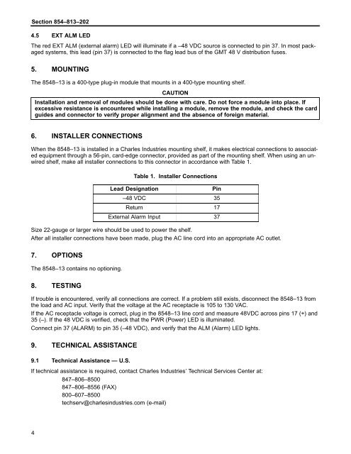
Table 1. Installer Connections<br />
Lead Designation<br />
Pin<br />
–<strong>48</strong> VDC 35<br />
Return 17<br />
External Alarm Input 37<br />
Size 22-gauge or larger wire should be used to power the shelf.<br />
After all installer connections have been made, plug the AC line cord into an appropriate AC outlet.<br />
7. OPTIONS<br />
The <strong>85<strong>48</strong></strong>–<strong>13</strong> contains no optioning.<br />
8. TESTING<br />
If trouble is encountered, verify all connections are correct. If a problem still exists, disconnect the <strong>85<strong>48</strong></strong>–<strong>13</strong> from<br />
the load and AC input. Verify that the voltage at the AC receptacle is 105 to <strong>13</strong>0 VAC.<br />
If the AC receptacle voltage is correct, plug in the <strong>85<strong>48</strong></strong>–<strong>13</strong> line cord and measure <strong>48</strong>VDC across pins 17 (+) and<br />
35 (–). If the <strong>48</strong> VDC is verified, check that the PWR (<strong>Power</strong>) LED is illuminated.<br />
Connect pin 37 (ALARM) to pin 35 (–<strong>48</strong> VDC), and verify that the ALM (Alarm) LED lights.<br />
9. TECHNICAL ASSISTANCE<br />
9.1 Technical Assistance — U.S.<br />
If technical assistance is required, contact <strong>Charles</strong> <strong>Industries</strong>’ Technical Services Center at:<br />
847–806–8500<br />
847–806–8556 (FAX)<br />
800–607–8500<br />
techserv@charlesindustries.com (e-mail)