AC 1000 Single-Slot T1 Mini Repeater Apparatus Case - Charles ...
AC 1000 Single-Slot T1 Mini Repeater Apparatus Case - Charles ...
AC 1000 Single-Slot T1 Mini Repeater Apparatus Case - Charles ...

You also want an ePaper? Increase the reach of your titles
YUMPU automatically turns print PDFs into web optimized ePapers that Google loves.
Telecommunications Group<br />
Section <strong>AC</strong>1−000−003<br />
Equipment Issue 3<br />
Fourth Printing, August 2005<br />
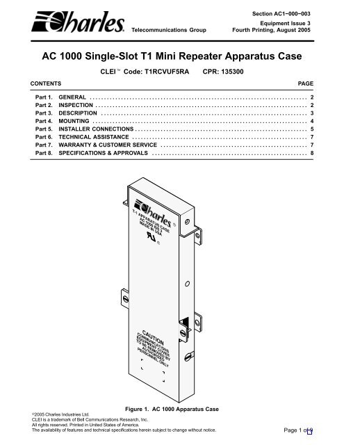
<strong>AC</strong> <strong>1000</strong> <strong>Single</strong>-<strong>Slot</strong> <strong>T1</strong> <strong>Mini</strong> <strong>Repeater</strong> <strong>Apparatus</strong> <strong>Case</strong><br />
CLEI Code: <strong>T1</strong>RCVUF5RA CPR: 135300<br />
CONTENTS<br />
PAGE<br />
Part 1. GENERAL . . . . . . . . . . . . . . . . . . . . . . . . . . . . . . . . . . . . . . . . . . . . . . . . . . . . . . . . . . . . . . . . . . . . . . . . . . . . . 2<br />
Part 2. INSPECTION . . . . . . . . . . . . . . . . . . . . . . . . . . . . . . . . . . . . . . . . . . . . . . . . . . . . . . . . . . . . . . . . . . . . . . . . . . . 2<br />
Part 3. DESCRIPTION . . . . . . . . . . . . . . . . . . . . . . . . . . . . . . . . . . . . . . . . . . . . . . . . . . . . . . . . . . . . . . . . . . . . . . . . . 3<br />
Part 4. MOUNTING . . . . . . . . . . . . . . . . . . . . . . . . . . . . . . . . . . . . . . . . . . . . . . . . . . . . . . . . . . . . . . . . . . . . . . . . . . . . 4<br />
Part 5. INSTALLER CONNECTIONS . . . . . . . . . . . . . . . . . . . . . . . . . . . . . . . . . . . . . . . . . . . . . . . . . . . . . . . . . . . . . 5<br />
Part 6. TECHNICAL ASSISTANCE . . . . . . . . . . . . . . . . . . . . . . . . . . . . . . . . . . . . . . . . . . . . . . . . . . . . . . . . . . . . . . 7<br />
Part 7. WARRANTY & CUSTOMER SERVICE . . . . . . . . . . . . . . . . . . . . . . . . . . . . . . . . . . . . . . . . . . . . . . . . . . . . 7<br />
Part 8. SPECIFICATIONS & APPROVALS . . . . . . . . . . . . . . . . . . . . . . . . . . . . . . . . . . . . . . . . . . . . . . . . . . . . . . . 8<br />
ÇÇ<br />
Figure 1. <strong>AC</strong> <strong>1000</strong> <strong>Apparatus</strong> <strong>Case</strong><br />
2005 <strong>Charles</strong> Industries Ltd.<br />
CLEI is a trademark of Bell Communications Research, Inc.<br />
All rights reserved. Printed in United States of America.<br />
The availability of features and technical specifications herein subject to change without notice. Page 1 of 9
Section <strong>AC</strong>1−000−003<br />
1. GENERAL<br />
1.1 Document Purpose<br />
This document provides general and installation information for the <strong>Charles</strong> Industries <strong>AC</strong> <strong>1000</strong> <strong>Single</strong>-<strong>Slot</strong> <strong>T1</strong><br />
<strong>Apparatus</strong> <strong>Case</strong>, shown in Figure 1.<br />
1.2 Document Status<br />
This document is updated to change the termonology “rubber grommets” to “grommets”. Figure 2 and Figure 4<br />
have been updated to show the correct grommets.<br />
1.3 Equipment Function<br />
The <strong>AC</strong> <strong>1000</strong> <strong>Apparatus</strong> <strong>Case</strong> provides mounting for one 238-type (unprotected), one 239-type (protected) <strong>T1</strong><br />
span line mini repeater, or one 270 SmartSpan repeater. (The 239-type repeater is recommended due to the<br />
secondary surge protection provided in these units. In all cases, building entrance primary protection MUST be<br />
provided per local practice.) The <strong>AC</strong> <strong>1000</strong> can be used to provision DS1 service offerings where cable losses dictate<br />
the need for a regenerator at or near the customer’s premises. The <strong>AC</strong> <strong>1000</strong> is used in lieu of larger apparatus<br />
housings and provides DS1 service at a reduced cost.<br />
1.4 Equipment Location/Mounting<br />
The <strong>AC</strong> <strong>1000</strong> <strong>Apparatus</strong> <strong>Case</strong> is designed for indoor mounting at or near the customer’s premises, and is typically<br />
mounted on a wood backboard.<br />
1.5 Equipment Features<br />
The <strong>AC</strong> <strong>1000</strong> case features the following:<br />
Light-weight all-aluminum case material<br />
<br />
<br />
<br />
<br />
<br />
<br />
Trim, stackable, piggy-back design saves wall space and provides snug fit for mini repeaters<br />
Interior card-edge connector for mini repeater<br />
Interior terminal block for input, output and fault locate connections<br />
Wiring diagram label for terminal screw functions on inside cover<br />
Top cap for repeater protection<br />
Two cable ties<br />
2. INSPECTION<br />
2.1 Inspect for Damages<br />
Inspect the equipment thoroughly upon delivery. If the equipment has been damaged in transit, immediately report<br />
the extent of damage to the transportation company.<br />
2.2 Equipment Identification<br />
<strong>Charles</strong> Industries’ equipment is identified by a model and issue number imprinted on the front panel or located<br />
elsewhere on the equipment. Each time a major engineering design change is made on the equipment, the issue<br />
number is advanced by 1 and imprinted on subsequent units manufactured. Therefore, be sure to include both<br />
the model number and its issue number when making inquiries about the equipment.<br />
2
ÇÇ<br />
ÇÇ<br />
Section <strong>AC</strong>1−000−003<br />
3. DESCRIPTION<br />
The aluminum <strong>AC</strong> <strong>1000</strong> <strong>Single</strong>-<strong>Slot</strong> <strong>T1</strong> <strong>Apparatus</strong> <strong>Case</strong> consists of three basic parts: a case base, a snap-on<br />
case cover, and a top repeater-access cap, which, when removed, provides access to the mini repeater card slot.<br />
3.1 <strong>Repeater</strong>-Access Cap<br />
The snap-on repeater-access cap (item A, Figure 2) functions as a dust or environmental cover, and is designed<br />
to fit over the top opening of the case.<br />
A<br />
=<strong>Repeater</strong> access cap<br />
A<br />
C<br />
B<br />
C<br />
D<br />
=<strong>Case</strong> cover<br />
=<strong>Case</strong> base<br />
=Mounting tabs (4)<br />
B<br />
F<br />
E<br />
G<br />
D<br />
D<br />
G<br />
ÍÍÍÍÍ<br />
D<br />
E<br />
F<br />
G<br />
H<br />
I<br />
J<br />
K<br />
L<br />
M<br />
N<br />
=Piggy-back stacking tabs &<br />
screws (2)<br />
=Wiring Diagram Label<br />
=<strong>Repeater</strong> stability tabs<br />
=<strong>Mini</strong> repeater connector<br />
=Terminal block<br />
=Ground stud<br />
=Security screws & slots<br />
=Wire access slots (2)<br />
=Ground wire slot<br />
=Grommets<br />
E<br />
K<br />
H<br />
ÍÍÍÍÍ<br />
ÍÍÍÍÍ<br />
D<br />
K<br />
K<br />
N<br />
L<br />
M<br />
I<br />
J<br />
L<br />
K<br />
Four<br />
Stacked<br />
<strong>Case</strong>s<br />
N<br />
3.2 <strong>Case</strong> Base<br />
Figure 2. <strong>AC</strong> <strong>1000</strong> <strong>Apparatus</strong> <strong>Case</strong><br />
The case base (item C, Figure 2) contains the following features:<br />
12-pin female card-edge connector (item H, Figure 2), for terminating the plug-in mini repeater<br />
(repeater connector contacts are gold-plated)<br />
<br />
<br />
<br />
Screw-type terminal block (item I, Figure 2), for terminating wire pairs to the repeater, including input,<br />
output, and fault locate output connections for both side 1 and side 2 of the repeater (the <strong>AC</strong> <strong>1000</strong> is<br />
shipped/pre-wired with jumpered fault locate outputs 2 and 7 strapped to ground)<br />
Ground stud, conveniently located at bottom end by wire entrance to facilitate connection to an<br />
approved ground source<br />
Three slots at the bottom; one slot for ground cable access and two keyhole-type with grommets for<br />
line/wire access<br />
3
Section <strong>AC</strong>1−000−003<br />
<br />
<br />
Four mounting tabs (ears)<br />
Two slotted screws (one on each side), which mate with slots in the housing cover to provide security<br />
and protection of internal electronics.<br />
3.3 <strong>Case</strong> Cover<br />
The case cover (item B, Figure 2) fits snugly over the case base, when the screw slots on the sides are properly<br />
aligned with the corresponding security screws on the sides of the case base. The front of the case cover is silkscreened<br />
with the company and equipment identification information, and on the inside of the cover is a wiring diagram<br />
label, as shown in Figure 2 and Figure 3. Also on the front are two “piggy-back” stacking tabs (item E<br />
Figure 2), one on each side, for securing apparatus cases together when multiple cases are stacked on top of<br />
each other. (To stack up to four cases together, see Mounting.)<br />
1 GRD<br />
2 FLT. LOCATE SIDE 1<br />
3 TIP-OUT<br />
SIDE 1<br />
4 RING-OUT<br />
5 TIP-IN SIDE 1<br />
6 RING-IN<br />
7 FLT. LOCATE SIDE 2<br />
8 TIP-OUT<br />
9 RING-OUT<br />
SIDE 2<br />
10 F.L. COMM-GRD<br />
11 TIP-IN<br />
12 RING-IN SIDE 2<br />
NOTES:<br />
1) REMOVE STRAPS FROM TERMINALS<br />
2 & 7 WHEN FAULT LOCATE IS USED.<br />
2) BIDIRECTIONAL SHOWN.<br />
Figure 3. Interior View of Cover, Bottom Half<br />
4. MOUNTING<br />
The <strong>AC</strong> <strong>1000</strong> is typically mounted on a wood backboard at the customer’s location. Use the following steps to<br />
mount the case(s:<br />
Step<br />
Action<br />
1. Locate the specified mounting location for the <strong>AC</strong> <strong>1000</strong> case or select a mounting location as close to<br />
the cable protector as possible.<br />
2. Remove the case cap(s) and cover(s), but do not completely remove the side security screws (item K,<br />
Figure 2).<br />
3. Position the case base on the backboard and mark the four mounting hole locations.<br />
4. Using four appropriate wood screws, secure the case base to the backboard at the marked locations.<br />
Note: Depending on the type of wood backboard used, it may be necessary to provide a pilot hole for<br />
the wood screws.<br />
5. If installing only one <strong>AC</strong> <strong>1000</strong> case, proceed to Part 5, Installer Connections.<br />
4
Section <strong>AC</strong>1−000−003<br />
Step<br />
Action<br />
6. When installing more than one <strong>AC</strong> <strong>1000</strong> case in a stacked or “piggy-back” fashion (see Figure 2), first<br />
perform Steps 1 through 7 in Part 5 for the bottom case before stacking the next case on top of it. Once<br />
the connections are made to the already-mounted bottom case and the cover is installed, remove the<br />
two “piggy-back” stacking screws (item F, Figure 2) from the bottom case cover. With the cover removed<br />
from the top or second case, place the top case base in front of the bottom case, carefully aligning<br />
the stacking tabs of the bottom case cover with the stacking tabs of the top case base. Secure the<br />
two together with the stacking tab screws just removed, one on each side. Then perform Steps 1−7 in<br />
Part 5 for the top case. Repeat entire procedure for a third and fourth case, if desired.<br />
7. After all units are mounted (Part 4) and wired (Part 5), the repeater-access cap(s) can be re-attached to<br />
the case(s).<br />
DO NOT stack more than four (4) units.<br />
CAUTION<br />
Card Edge<br />
Connector<br />
12 9 7 5 3 1<br />
Installer<br />
Connection<br />
Terminal<br />
Strip<br />
Cable tie<br />
Ground Stud<br />
for cable shield<br />
ground<br />
connection<br />
Grommet<br />
OUTPUT<br />
Shielded single<br />
pair wire or<br />
shielded multi−<br />
pair cable<br />
INPUT<br />
Figure 4. Interior View of Base, Bottom Half<br />
5. INSTALLER CONNECTIONS<br />
Follow the steps below to make the installer connections to the <strong>AC</strong> <strong>1000</strong> <strong>Apparatus</strong> <strong>Case</strong>.<br />
Step<br />
Action<br />
1. Access the Interior Screw Terminal Block<br />
If not already done, first slide off the top repeater access-cap and then remove the case cover. To remove<br />
the case cover, first loosen the two slotted screws (one on each side of the case) using a flatblade<br />
screwdriver, and then firmly lift off the case cover.<br />
2. Prepare Wire Ends<br />
The terminal block accepts 19 through 26 AWG copper wire. Strip 1/2-inch of insulation from the wire<br />
ends to be connected.<br />
5
Section <strong>AC</strong>1−000−003<br />
Step<br />
Action<br />
3. Route the Wires<br />
Route the stripped wires through the two 3/8”-inch holes (through the protective grommets) at the bottom<br />
of the case. (The middle slot directly below the ground stud is for the ground wire and does not require<br />
a grommet.)<br />
4. Connect Wires to Terminal Strip<br />
Make the appropriate connections per the wiring diagram shown in Figure 5. A quick-reference wiring<br />
diagram label is provided on the inside of the case cover. Note that the jumpered fault locate outputs at<br />
terminals 2 and 7 should always be strapped to ground, as shown in Figure 5, unless an external fault<br />
locate filter is specified.<br />
5. Connect Ground Wire<br />
A ground stud at the bottom center of the case base is used for connecting the ground wire and the<br />
ground shield of the transmit and receive pairs. Alternately the shields can be tied to positions 1 and 10<br />
on the terminal block, which are internally connected to ground.<br />
Note: The cable pair shields MUST only be grounded at one end.<br />
Note: Only one 14-gauge (minimum) earth ground wire is required for up to four stacked units.<br />
6. Install Cable Ties<br />
After all wiring connections are complete, further secure the wires on each side with the two cable ties<br />
provided, as shown in Figure 4.<br />
7. Close the <strong>Apparatus</strong> <strong>Case</strong><br />
After the wiring connections have been made, re-attach the cover to the base by aligning the side security<br />
slots on the cover with the side security screws on the base and then pressing together until they<br />
snap closed. Firmly tighten the two security screws on the case cover, one on each side.<br />
8. Insert <strong>Mini</strong> <strong>Repeater</strong><br />
With the mini repeater’s card edge close to the case base, slide the mini repeater into the apparatus<br />
case through the top slot opening, Firmly but gently push the mini repeater into the card-edge connector<br />
at the bottom of the case slot.<br />
9. Install <strong>Repeater</strong>-Access Cap<br />
When wiring is complete and the mini repeater is installed, further protect the apparatus case by installing<br />
the snap-on, top repeater-access cap.<br />
CAUTION<br />
Install and remove repeater with care. Do not force a repeater into place. If excessive resistance is<br />
encountered while installing, remove the repeater to check for proper alignment and an unobstructed<br />
insertion path and connector.<br />
6
Section <strong>AC</strong>1−000−003<br />
<strong>T1</strong> REPEATER<br />
BIDIRECTIONAL<br />
OPERATION<br />
NOTE 1<br />
1<br />
SIDE 1 OUT<br />
SIDE 2 OUT<br />
1<br />
F.L. SIDE 1 2<br />
1 SIDE 1 IN<br />
F.L. SIDE 2<br />
F.L.<br />
COMMON<br />
3<br />
4<br />
5<br />
6<br />
7<br />
8<br />
9<br />
10<br />
2 SIDE 2 IN<br />
11<br />
12<br />
1<br />
2<br />
3<br />
4<br />
5<br />
6<br />
7<br />
8<br />
9<br />
10<br />
11<br />
12<br />
2<br />
3<br />
4<br />
5<br />
6<br />
7<br />
8<br />
9<br />
10<br />
11<br />
12<br />
3<br />
4<br />
5<br />
6<br />
8<br />
9<br />
11<br />
12<br />
SHIELD<br />
T<br />
R<br />
T<br />
R<br />
OUTPUT<br />
SIDE 1<br />
INPUT<br />
SIDE 1<br />
<strong>Case</strong> Ground (Installer ground<br />
connection)<br />
T<br />
R<br />
T<br />
R<br />
OUTPUT<br />
SIDE 2<br />
NOTE 2<br />
INPUT<br />
SIDE 2<br />
NOTE 2<br />
NOTE 1: Units are shipped with jumpered fault locate outputs 2<br />
and 7 strapped to ground. Remove straps for external fault locate<br />
filter applications.<br />
NOTE 2: If unidirectional repeaters are used, the side 2 (only) regenerator<br />
inputs and outputs are reversed from that shown. The “customer” and<br />
“office” side connections are also reversed for side 2.<br />
Figure 5. Wiring Diagram of <strong>AC</strong> <strong>1000</strong> Equipped with Bi-directional (two-way) <strong>Repeater</strong>s<br />
6. TECHNICAL ASSISTANCE<br />
If technical assistance is required, contact <strong>Charles</strong> Industries’ Technical Services Center at:<br />
847−806−8500<br />
847−806−8556 (FAX)<br />
800−607−8500<br />
techserv@charlesindustries.com (e-mail)<br />
7. WARRANTY & CUSTOMER SERVICE<br />
7.1 Warranty<br />
<strong>Charles</strong> Industries, Ltd. offers an industry-leading, 5-year warranty on products manufactured by <strong>Charles</strong> Industries.<br />
Contact your local Sales Representative at the address or telephone numbers below for warranty details.<br />
The warranty provisions are subject to change without notice. The terms and conditions applicable to any specific<br />
sale of product shall be defined in the resulting sales contract.<br />
<strong>Charles</strong> Industries, Ltd.<br />
5600 Apollo Drive<br />
Rolling Meadows, Illinois 60008−4049<br />
847−806−6300 (Main Office)<br />
847−806−6231 (FAX)<br />
7
Section <strong>AC</strong>1−000−003<br />
7.2 Field Repairs (In-Warranty Units)<br />
Field repairs involving the replacement of components within a unit are not recommended and may void the warranty<br />
and compatibility with any applicable regulatory or agency requirements. If a unit needs repair, contact<br />
<strong>Charles</strong> Industries, Ltd. for replacement or repair instructions, or follow the Repair Service Procedure below.<br />
7.3 Advanced Replacement Service (In-Warranty Units)<br />
<strong>Charles</strong> Industries, Ltd. offers an “advanced replacement” service if a replacement unit is required as soon as<br />
possible. With this service, the unit will be shipped in the fastest manner consistent with the urgency of the situation.<br />
In most cases, there are no charges for in-warranty repairs, except for the transportation charges of the unit<br />
and for a testing and handling charge for units returned with no trouble found. Upon receipt of the advanced replacement<br />
unit, return the out-of-service unit in the carton in which the replacement was shipped, using the preaddressed<br />
shipping label provided. Call your customer service representative at the telephone number above for<br />
more details.<br />
7.4 Standard Repair and Replacement Service (Both In-Warranty and Out-Of-Warranty Units)<br />
<strong>Charles</strong> Industries, Ltd. offers a standard repair or exchange service for units either in- or out-of-warranty. With<br />
this service, units may be shipped to <strong>Charles</strong> Industries for either repair and quality testing or exchanged for a<br />
replacement unit, as determined by <strong>Charles</strong> Industries. Follow the Repair Service Procedure below to return units<br />
and to secure a repair or replacement. A handling charge applies for equipment returned with no trouble found. To<br />
obtain more details of this service and a schedule of prices, contact the CI Service Center at 217−932−5288 (FAX<br />
217−932−2943).<br />
Repair Service Procedure<br />
1. Prepare, complete, and enclose a purchase order in the box with the equipment to be returned.<br />
2. Include the following information:<br />
− Company name and address<br />
− Contact name and phone number<br />
− Inventory of equipment being shipped<br />
− Particulars as to the nature of the failure<br />
− Return shipping address<br />
3. Ship the equipment, purchase order, and above-listed information, transportation prepaid, to the service<br />
center address shown below.<br />
CI Service Center<br />
503 N.E. 15th St., P.O. Box 339<br />
<strong>Case</strong>y, IL 62420−2054<br />
4. Most repaired or replaced units will be returned within 30 or 45 days, depending on the product type<br />
and availability of repair parts. Repaired units are warranted for either 90 days from the date of repair<br />
or for the remaining unexpired portion of the original warranty, whichever is longer.<br />
8. SPECIFICATIONS & APPROVALS<br />
8.1 Regulatory/Agency Approvals<br />
The following regulatory agency approvals apply to the <strong>AC</strong> <strong>1000</strong>.<br />
UL Listed under Underwriters Laboratories Standard 1459, Second Edition. Compliance is restricted<br />
to inside plant wiring. Field repairs may void compliance.<br />
8.2 Electrical Specifications<br />
The electrical characteristics of the <strong>AC</strong> <strong>1000</strong> are as follows:<br />
Compatible with <strong>T1</strong>, <strong>T1</strong>C, <strong>T1</strong>D, and <strong>T1</strong>G Carrier Systems.<br />
8
Section <strong>AC</strong>1−000−003<br />
8.3 Physical Specifications<br />
The physical characteristics of the <strong>AC</strong> <strong>1000</strong> are shown in Table 1.<br />
Table 1. Physical Specifications<br />
Feature U.S. Metric<br />
Height (incl. cap) 9.375 inches 23.5 centimeters<br />
Width (incl. mounting tabs) 3.75 inches 9.5 centimeters<br />
Depth (incl. stacking screws) 1 inch 2.54 centimeters<br />
Weight (without repeater) 7 ounces 198.5 grams<br />
Temperature 32 to 120 F 0 to 49 C<br />
Humidity<br />
To 95% (no condensation)<br />
<br />
9