360â22 D4 Digital Carrier Terminal General Description, Application ...
360â22 D4 Digital Carrier Terminal General Description, Application ...
360â22 D4 Digital Carrier Terminal General Description, Application ...

Create successful ePaper yourself
Turn your PDF publications into a flip-book with our unique Google optimized e-Paper software.
Telecommunications Group<br />
Section 360–022–502<br />
Equipment Issue 2<br />
First Printing, December 2000<br />
360–22 <strong>D4</strong> <strong>Digital</strong> <strong>Carrier</strong> <strong>Terminal</strong> <strong>General</strong> <strong>Description</strong>,<br />
<strong>Application</strong> and Installation Procedures<br />
CONTENTS<br />
PAGE<br />
Part 1. GENERAL . . . . . . . . . . . . . . . . . . . . . . . . . . . . . . . . . . . . . . . . . . . . . . . . . . . . . . . . . . . . . . . . . . . . . . . . . . . . . 2<br />
Part 2. INSPECTION . . . . . . . . . . . . . . . . . . . . . . . . . . . . . . . . . . . . . . . . . . . . . . . . . . . . . . . . . . . . . . . . . . . . . . . . . . . 2<br />
Part 3. APPLICATION GUIDELINES . . . . . . . . . . . . . . . . . . . . . . . . . . . . . . . . . . . . . . . . . . . . . . . . . . . . . . . . . . . . . 3<br />
Part 4. SYSTEM DESCRIPTION . . . . . . . . . . . . . . . . . . . . . . . . . . . . . . . . . . . . . . . . . . . . . . . . . . . . . . . . . . . . . . . . . 4<br />
Part 5. INSTALLER CONNECTIONS . . . . . . . . . . . . . . . . . . . . . . . . . . . . . . . . . . . . . . . . . . . . . . . . . . . . . . . . . . . . . 6<br />
Part 6. TESTING/TROUBLESHOOTING . . . . . . . . . . . . . . . . . . . . . . . . . . . . . . . . . . . . . . . . . . . . . . . . . . . . . . . . 10<br />
Part 7. TECHNICAL ASSISTANCE . . . . . . . . . . . . . . . . . . . . . . . . . . . . . . . . . . . . . . . . . . . . . . . . . . . . . . . . . . . . . 11<br />
Part 8. WARRANTY & CUSTOMER SERVICE . . . . . . . . . . . . . . . . . . . . . . . . . . . . . . . . . . . . . . . . . . . . . . . . . . . 11<br />
Part 9. SPECIFICATIONS . . . . . . . . . . . . . . . . . . . . . . . . . . . . . . . . . . . . . . . . . . . . . . . . . . . . . . . . . . . . . . . . . . . . . 14<br />
Figure 1. <br />
2000 Charles Industries Ltd.<br />
CLEI is a trademark of Bell Communications Research, Inc.<br />
All rights reserved. Printed in United States of America.<br />
The availability of features and technical specifications herein subject to change without notice. Page 1 of 14
Section 360–022–502<br />
1. GENERAL<br />
1.1 Document Purpose<br />
This document provides a general description and installation information for the Charles Industries 360–22 <strong>D4</strong><br />
<strong>Digital</strong> <strong>Carrier</strong> <strong>Terminal</strong> (DCT) assembly. The 360–22 DCT (also known as a channel bank), when equipped, provides<br />
1:1 protected common equipment, insuring that no single point failure can affect more than one channel.<br />
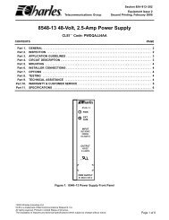
The 360–22 DCT can accept any 360 family channel unit. The 360–22 DCT is provided in 19-inch mechanics as<br />
depicted in Figure 1.<br />
1.2 Equipment Function<br />
The 360–22 DCT terminates a DS1 PCM carrier facility, from which it derives up to 24 voice or data communication<br />
channels. Each channel is represented by a numbered slot in the channel bank, and is equipped for the required<br />
service by installing the appropriate Charles Industries channel unit. Each channel unit slot is universal,<br />
i.e., each slot will mount any type of Charles Industries 360 channel unit.<br />
1.3 Equipment Mounting<br />
The 360–22 <strong>Digital</strong> <strong>Carrier</strong> <strong>Terminal</strong> (DCT) is provided in 19–inch standard rack mount mechanics and is intended<br />
for mounting in channel rack assemblies. Dimensions are described in Part 9.<br />
The 360–22 DCT is intended for mounting in an indoor protected environment with an ambient temperature of<br />
0–50 C (32–120 F).<br />
1.4 Equipment Features<br />
The 360–22 <strong>D4</strong> DCT includes the following features:<br />
<br />
<br />
<br />
<br />
<br />
<br />
<br />
<br />
Fully 1:1 protected common equipment<br />
24 channel unit capacity<br />
Rear cover<br />
Optional smoked polycarbonate front cover, part number 97–001671–A<br />
Connectorized terminations for all transmissions pairs<br />
–48 VDC or +/–24 VDC (nominal) input voltage<br />
Accepts any 360–family channel units<br />
DDS composite clock output or synchronization<br />
2. INSPECTION<br />
2.1 Inspect for Damages<br />
Inspect the equipment thoroughly upon delivery. If the equipment has been damaged in transit, immediately report<br />
the extent of damage to the transportation company.<br />
2.2 Equipment Identification<br />
Charles Industries’ equipment is identified by a model and issue number imprinted on the front panel or located<br />
elsewhere on the equipment. Each time a major engineering design change is made on the equipment, the issue<br />
number is advanced by 1 and imprinted on subsequent units manufactured. Therefore, be sure to include both<br />
the model number and its issue number when making inquiries about the equipment.
3. APPLICATION GUIDELINES<br />
The 360–22 <strong>Digital</strong> <strong>Carrier</strong> <strong>Terminal</strong> (DCT) provides a high degree of reliability via its duplicated common equipment.<br />
It is ideally suited for mission-critical applications where downtime cannot be tolerated.<br />
The unit provides termination and multiplex for a single DS1 facility, and can be equipped with up to 24 voice or<br />
data channel units from the 360 family. Channel units can be freely intermixed in any of the 24 channel unit positions.<br />
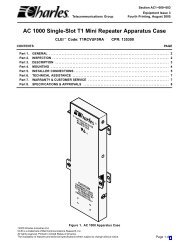
Channel units are equipped in slots J1 through J24, as shown in Figure 2. The subsequent sections assume<br />
that the 360–22 DCT assembly is equipped with two 3603–02 Line Interface Units (LIU–3E), two 3608–04<br />
Digroup Interface Units – Redundant (DIU–R), and two 3609–04 or 3609–22 (+/–24 VDC) Power Supply Units –<br />
Redundant (PSU–R), as described below.<br />
The 360–22 DCT provides six common equipment slots, J25 through J30, as shown in Figure 2. These slots are<br />
equipped with appropriate common equipment modules as described in the following paragraphs.<br />
Common equipment slots J27 and J30 are designed to accept the 3609–04 or 3609–22 (+/–24 VDC) PSU–R<br />
modules. Slot J27 is designated the “A” PSU–R slot and slot J30 is the “B” position.<br />
Common equipment slots J25 and J26 are provided to accept the 3608–04 DIU–R modules. Slot J25 is designated<br />
the “A” DIU–R position, and slot J26 is the “B” position.<br />
Common equipment slots J28 and J29 are provided to accept the 3603–02 Line Interface Units (LIU–3E). Slot<br />
J28 is designated the “A” LIU–3E position, and slot J29 is the “B” position.<br />
All installer connections are made to terminal blocks or connectors at the rear of the assembly. These are shown<br />
in Figure 3. Refer to Part 5. for detailed information on these connections.<br />
The 360–22 DCT connects to a 1.544 Mb/s DS1 facility. The 360–22 DCT can operate with either <strong>D4</strong> (Superframe)<br />
or ESF (Extended Superframe) framing.<br />
Options are provided to operate with either a D1D, D2 or D3 channel counting sequence. Unless required to provide<br />
far end compatibility, the terminal should be optioned for the D3 (sequential) channel counting sequence. The<br />
D3 sequence maps channel unit position number 1 into timeslot 1, unit position 2 into timeslot 2, etc.<br />
The DS1 line code can be selected as either alternate mark inversion (AMI) or B8ZS. B8ZS coding should be selected<br />
if the DCT is to be equipped with data channel units that require 64Kb/s “clear channel” operation.<br />
The 360–22 DCT can be optioned to operate in one of three possible timing modes: free-run, synchronized to the<br />
incoming DS1 signal (also known as loop-timed), or synchronized to an external source of composite clock.<br />
By selection of the appropriate channel unit, the 360–22 DCT can provide a wide range of analog (voice) and<br />
data services. Analog channel units are available in 2-wire (2W) or 4-wire (4W) configurations and can provide<br />
TO, E&M, PLR, FXS, FXO, DPO, DPT, Ringdown and DX signaling arrangements. Wideband analog program<br />
channels at 5kHz and 15kHz are also available. Data channel units are available with OCU 4W interfaces at rates<br />
from 2.4 to 64Kb/s, and with EIA data interfaces (RS232, RS422, and V.35) at rates from 2.4 Kb/s to 1.536 Mb/s.<br />
Channel Units<br />
J1 J2 J3 J4 J5 J6 J7 J8 J9 J10 J11 J12<br />
J13 J14 J15 J16 J17 J18 J19 J20 J21 J22 J23 J24<br />
3608–04 DIU–R<br />
J25–A<br />
3608–04 DIU–3R<br />
J26–B<br />
3609–04 PSU–R<br />
J27–A<br />
3603–02 LIU–3E<br />
J28–A<br />
3603–02 LIU–3E<br />
J29–B<br />
3609–04 PSU–R<br />
J30–B<br />
Digroup<br />
Interface Units<br />
Power<br />
Supply Units<br />
Line<br />
Interface Units<br />
Figure 2.
Section 360–022–502<br />
<br />
<br />
<br />
<br />
<br />
<br />
<br />
<br />
<br />
TERM BRIDGE<br />
COMPOSITE<br />
CLOCK<br />
<br />
OVRD<br />
MAJ<br />
AUD<br />
VIS<br />
8–48VRB<br />
7 –48VB<br />
6–48VRA<br />
5 –48VA<br />
4 RVRB<br />
3 RVB<br />
2 RVRA<br />
1 RVA<br />
8<br />
7<br />
6<br />
5<br />
4<br />
3<br />
2<br />
1<br />
REMA<br />
REMB<br />
GND<br />
RT1R<br />
RT1T<br />
GND<br />
XT1R<br />
XT1T<br />
8<br />
7<br />
6<br />
5<br />
4<br />
3<br />
2<br />
1<br />
FRG<br />
T1 NET<br />
<br />
FRG<br />
ALARMS<br />
<br />
POWER<br />
<br />
T1 NET<br />
<br />
Figure 3. <br />
4. SYSTEM DESCRIPTION<br />
Refer to the system functional block diagram of the 360–22 <strong>Digital</strong> <strong>Carrier</strong> <strong>Terminal</strong> (DCT), shown in Figure 4,<br />
when reading this description.<br />
As shown in Figure 4, the 360–22 is equipped with two complete common equipment sets. Each set consists of<br />
one 3603–02 Line Interface Unit (LIU–3E), one 3608–04 Digroup Interface Unit (DIU–R), and one 3609–04 or<br />
3609–22 Power Supply Unit (PSU–R). The sets are configured in two 1:1 protected groups, A and B.<br />
The PSU–R modules operate in a load-sharing configuration. Each supply provides the complete set of system<br />
voltages including 48Vdc “talk battery” for FXS channel units. The power supplies are continuously monitored by<br />
the protection switch controller which is located on the DIU–R units.<br />
The A and B side 3603–02 LIU–3E units provide an interface between the bipolar DS1 facility and the framing<br />
and channel sequencing circuitry of the DIU–R. The LIU–3E also provides clocking and synchronization functions<br />
for the system.<br />
The A and B side DIU–R units provide DS1 receive framing and transmit alignment. The DIU–R controls the<br />
channel unit bus and determines the channel unit timing sequences. Alarm and trunk processing logic is also performed<br />
by the DIU–R. Each DIU–R contains a microprocessor control facility to control the 1:1 redundancy<br />
switching.<br />
Control of the system protection switching is constantly maintained and arbitrated by the two DIU–R units. On<br />
system power-up or upon DIU–R plug-in insertion, the DIU–R units will perform a configuration check of the PCB<br />
mounted switch settings and exchange that information with the alternate DIU–R. If a discrepancy exists in the<br />
configuration, a warning message will be displayed on the unit’s front panel as to which settings are incorrect.<br />
Further DIU–R processing will be halted until the discrepancy is corrected.<br />
After satisfactorily completing the configuration check, the system will go into service, assuming there are no other<br />
faults. Either the A or B side DIU–R will take control, displaying ACTV (active) on its front panel display. The<br />
other DIU–R will display STBY (standby). Both units, however, will continue to monitor system performance<br />
through their background checking routines.
J32/TB3D<br />
T1<br />
FACILITY<br />
<br />
<br />
<br />
<br />
<br />
<br />
<br />
<br />
<br />
<br />
<br />
<br />
<br />
<br />
<br />
<br />
<br />
<br />
<br />
<br />
P1, P2<br />
P3, P4<br />
DERIVED<br />
VOICE/DATA<br />
FACILITIES<br />
<br />
<br />
<br />
<br />
<br />
<br />
<br />
<br />
<br />
<br />
FRG<br />
<br />
Figure 4. <br />
When a common equipment fault is detected by either DIU–R, both DIU–R units will exchange monitoring data,<br />
and the appropriate common equipment set will become active. The DIU–R side associated with the fault will display<br />
the type of fault on its front panel and cause the system to generate a minor alarm.<br />
When the fault has been cleared, the fault-side DIU–R will display the STBY message and retire the minor alarm.<br />
4.1 Alarm, Status, and Control<br />
The 360–22 DCT provides three sets of alarm output contacts, designated MAJ (major), AUD (audible) and VIS<br />
(visual). These alarms appear at TB2 at the system back panel. The operation of these alarms are in conjunction<br />
with two option switches, designated WW and MA, which are located on the 3609–04 PSU–R modules. Consult<br />
Section 360–904–201 for a discussion of these options.<br />
When the system declares a minor alarm, a contact closure will be presented across the AUD and VIS alarm outputs<br />
for the duration of the alarm condition. When the system declares a major alarm, a contact closure will be<br />
presented across the MAJ, AUD, and VIS outputs for the duration of the alarm condition.<br />
The 360–22 DCT provides two control inputs, designated REMA and REMB, and a status output, designated<br />
OVRD, that are all associated with the common equipment protective switching feature. The REMA and REMB<br />
inputs are used to force either the A side or B side into the active state. A momentary ground on the input will<br />
force a switch to that side, but allow the transfer to revert to the other side if a fault is subsequently detected. A<br />
continuous ground on the input will force the common equipment to transfer to that side and inhibit further switching.<br />
Whenever the REMA and REMB inputs are at ground, the OVRD output will present a contact closure.
Section 360–022–502<br />
5. INSTALLER CONNECTIONS<br />
The 360–22 <strong>Digital</strong> <strong>Carrier</strong> <strong>Terminal</strong> (DCT) may be installed in 19” rack or cabinet assemblies. Alternately, the<br />
360–22 DCT may be provided in factory–prewired rack assemblies, consisting of one or more DCT assemblies,<br />
plus other equipment as specified. The following paragraphs describe the 360–22 DCT installation procedure for<br />
a single DCT installation.<br />
5.1 Input Power Connections<br />
5.1.1. –48 Volt Input Power Connections<br />
All input power connections are made to <strong>Terminal</strong> Block TB4 at the rear of the unit, as shown in Figure 3 and<br />
Figure 5. The 360–22 DCT provides for two separate –48V power inputs. If the 360–22 DCT is to be equipped<br />
with channel units that require 20Hz ringing, the DCT must be supplied with an external negative superimposed<br />
ringing source. External ringing input is supplied to terminal block TB4. Two separate ringing inputs are provided.<br />
Connect the two –48V input power feeders to TB4 terminals –48VA and –48VB, and a positive return (ground) to<br />
–48VRA and –48VRB, respectively. Connections to TB4 can be made to the screw terminals using 14 ga<br />
stranded insulated wire, color-coded per Figure 5. Each battery input should be individually externally fused at 7.5<br />
amps.<br />
Connect negative superimposed ringing voltage to TB4 terminals RVA and RVB. Connect the ringing return<br />
(ground) to TB4 terminals RVRA and RVRB. Ringing voltage wiring should be provided via 22 gauge solid twisted<br />
pair, color-coded per Figure 5.<br />
<br />
–48VRB<br />
–48VB<br />
8<br />
7<br />
BLK<br />
RED<br />
<br />
<br />
ground<br />
battery<br />
B side<br />
48V input<br />
–48VRA<br />
–48VA<br />
6<br />
5<br />
BLK<br />
RED<br />
<br />
<br />
ground<br />
battery<br />
A side<br />
48V input<br />
RVRB<br />
RVB<br />
RVRA<br />
RVA<br />
4<br />
3<br />
2<br />
1<br />
<br />
BLK<br />
GRN<br />
BLK<br />
GRN<br />
ground<br />
negative<br />
super-<br />
imposed<br />
ground<br />
negative<br />
super-<br />
imposed<br />
B side<br />
ringing input<br />
A side<br />
ringing input<br />
<br />
<br />
Figure 5. <br />
5.1.2. +/–24 Volt Input Power Connections<br />
Before making connections, remove all modules from the bank and disconnect any pre-existing power connections.<br />
Locate and peel the label shipped with the 3609–22 PSU and install it over the 360–22 channel bank TB4<br />
power terminal strip.<br />
All input power connections are made to <strong>Terminal</strong> Block TB4 at the rear of the unit, as shown in Figure 3,<br />
Figure 6, and Figure 7. The DCT provides for two separate +/– 24V power inputs. If the DCT is to be equipped<br />
with channel units that require 20Hz ringing, the DCT must be supplied with an external negative superimposed<br />
ringing source. External ringing input is supplied to terminal block TB4. Two separate ringing inputs are provided.<br />
Connections to TB4 can be made to the screw terminals using 14 ga stranded insulated wire, color-coded per<br />
Figure 6 (for –24 volts) and Figure 7 (for +24 volts). Each battery input should be individually externally fused at<br />
7.5 amps.<br />
Ringing voltage wiring should be provided via 22 ga solid twisted pair, color-coded per Figure 6 (for –24 volts)<br />
and Figure 7 (for +24 volts).
INSTALLER CONNECTIONS<br />
<br />
<br />
8<br />
7<br />
BLK<br />
RED<br />
<br />
<br />
ground<br />
battery<br />
B side<br />
–24 VDC<br />
source<br />
<br />
<br />
6<br />
5<br />
BLK<br />
RED<br />
<br />
<br />
ground<br />
battery<br />
A side<br />
–24 VDC<br />
source<br />
<br />
<br />
<br />
<br />
<br />
3<br />
<br />
<br />
<br />
BLK<br />
GRN<br />
BLK<br />
GRN<br />
ground<br />
negative<br />
super-<br />
imposed<br />
ground<br />
negative<br />
super-<br />
imposed<br />
B side<br />
ringing input<br />
A side<br />
ringing input<br />
TB4<br />
<br />
Figure 6. <br />
INSTALLER CONNECTIONS<br />
<br />
<br />
8<br />
7<br />
BLK<br />
PINK<br />
<br />
<br />
ground<br />
battery<br />
B side<br />
+24 VDC<br />
source<br />
<br />
<br />
6<br />
5<br />
BLK<br />
PINK<br />
<br />
<br />
ground<br />
battery<br />
A side<br />
+24 VDC<br />
source<br />
<br />
<br />
<br />
3<br />
PINK<br />
GRN<br />
+24 V<br />
grounded<br />
ring supply<br />
B side<br />
ringing input<br />
<br />
<br />
<br />
<br />
<br />
PINK<br />
GRN<br />
+ 24 V<br />
grounded<br />
ring supply<br />
A side<br />
ringing input<br />
TB4<br />
<br />
Figure 7. <br />
Note:<br />
For more information, refer to the documentation that comes with the +/– 24 volt power source.<br />
For –24 volt power connections<br />
Use the following steps if the application requires a MINUS (–) 24 volt input source:<br />
Step<br />
Action<br />
1. Connect the PLUS lead of the Side A power source to the terminal labelled VRA.<br />
2. Connect the PLUS lead of the Side B power source to the terminal labelled VRB.<br />
3. Connect the MINUS lead of the Side A power source through a 7.5-amp fuse to the terminal labelled<br />
VA.<br />
4. Connect the MINUS lead of the Side B power source through a 7.5-amp fuse to the terminal labelled<br />
VB.
Section 360–022–502<br />
For +24 volt power connections<br />
Use the following steps if the application requires a PLUS (+) 24 volt input source:<br />
Step<br />
Action<br />
1. Connect the MINUS lead of the Side A power source to the terminal labelled VRA.<br />
2. Connect the MINUS lead of the Side B power source to the terminal labelled VRB.<br />
3. Connect the PLUS lead of the Side A power source through a 7.5-amp fuse to the terminal labelled VA.<br />
4. Connect the PLUS lead of the Side B power source through a 7.5-amp fuse to the terminal labelled VB.<br />
5.2 Frame Ground<br />
As shown in Figure 3, a chassis frame ground lug is provided at the rear panel. Connect this to the office frame<br />
ground via a minimum 14 gauge wire.<br />
5.3 DS1 Facility Connections<br />
The DS1 facility is connected to either TB3 or connector J32. These connectors are in parallel, allowing use of<br />
either one in a particular installation. J32 is a female 15-pin D-subminiature connector. The connections to<br />
TB3/J32 are shown in Figure 8.<br />
5.4 Voice/Data Channel Unit Connections<br />
The channel unit connections are available on connectors P1, P2, P3, and P4 as shown in Figure 3. These connectors<br />
are 25-pair male connectors and mate with appropriate female connectors (Cinch 222–22–50–023 or<br />
equivalent). Pin out and signal identification for P1 through P4 is shown in Figure 13 and Figure 14. Cable assemblies,<br />
consisting of the appropriate mating female connectors and 25-pair cable, are available separately in<br />
lengths up to 150 feet.<br />
5.5 Composite Clock (Synchronization Input Connectors)<br />
If the 360–22 DCT is to be synchronized to a source of external composite clock, the clock input is made via connector<br />
J33, a female 9-pin D-subminiature, as shown in Figure 10. Each DCT can be fed from a single timing supply<br />
output, all 360–22 DCTs in a bay assembly can have their clock inputs daisy–chained. The last DCT in the<br />
chain (farthest from the timing supply output) must provide for termination of the clock signal. This is accomplished<br />
by placing switch S1, located at the back panel, to the TERM position. All other DCTs in the chain should<br />
have S1 in the BRIDGE position. If the DCTs are individually fed timing, S1 should be in the TERM position.<br />
5.6 System Status And Control<br />
The 360–22 DCT provides a contact closure output, designated OVRD, on terminals 8 and 7 of TB2 (see<br />
Figure 12). The system will present a contact closure across these terminals whenever a common equipment<br />
transfer is being forced. Connect these terminals to the appropriate office system. The 360–22 DCT also provides<br />
two control inputs designated REMA and REMB, at terminals 8 and 7 of TB3 (see Figure 12). These inputs accept<br />
a ground (–48VR) input to force a common equipment to transfer. Connect these inputs to the appropriate<br />
office control system.<br />
5.7 System Alarm Connections<br />
External alarm outputs are provided at terminal block TB2 as shown in Figure 9. These should be connected as<br />
appropriate to the office alarm system. Three alarm outputs are provided: MAJ (major), AUD (audible), and VIS<br />
(visual). Each output provides a relay contact which is open during the normal (non–alarmed) condition, and<br />
closes during alarm.<br />
5.8 Composite Clock Output<br />
The active DIU–R unit allows its corresponding LIU–3E unit to output a composite clock signal to pins 1 and 6 of<br />
J33 on the rear panel. The composite clock signal can be used to synchronize another 360–22 with DDS dataport<br />
channels in tandem with this 360–22.
Remote override inputs.<br />
INSTALLER<br />
CONNECTIONS<br />
<br />
<br />
<br />
<br />
<br />
<br />
<br />
<br />
<br />
<br />
<br />
<br />
<br />
<br />
<br />
<br />
<br />
<br />
<br />
<br />
<br />
<br />
<br />
INSTALLER CONNECTIONS<br />
DS1<br />
FACILITY<br />
<br />
<br />
<br />
<br />
<br />
<br />
<br />
<br />
<br />
<br />
<br />
<br />
<br />
<br />
<br />
<br />
<br />
<br />
<br />
<br />
<br />
DS1<br />
FACILITY<br />
Figure 8. <br />
OVRD<br />
<br />
<br />
STATUS OUTPUT<br />
MAJ<br />
<br />
<br />
AUD<br />
<br />
<br />
To Office<br />
Alarm System<br />
VIS<br />
<br />
<br />
TB2<br />
ALARMS<br />
INSTALLER CONNECTIONS<br />
Figure 9. <br />
Refer to<br />
Figure 11<br />
<br />
<br />
<br />
<br />
<br />
<br />
<br />
<br />
From timing supply<br />
or from previous DCT<br />
To tandem<br />
360–22<br />
<br />
<br />
<br />
<br />
To next<br />
DCT<br />
INSTALLER CONNECTIONS<br />
Figure 10.
Section 360–022–502<br />
LIU–3E (A)<br />
61<br />
63<br />
8<br />
3<br />
Composite Clock<br />
Input<br />
62<br />
64<br />
Relay (A) Control<br />
from 3608–04 (A)<br />
pin 19<br />
X<br />
X<br />
Relay (A)<br />
6<br />
1<br />
To J35<br />
pins<br />
Composite Clock<br />
Output<br />
LIU–3E (B)<br />
61<br />
63<br />
62<br />
64<br />
X<br />
X<br />
Relay (B) Control<br />
from 3608–04 (B)<br />
pin 19<br />
Relay (B)<br />
Figure 11. LIU–3E Wiring<br />
OVRD<br />
8<br />
7<br />
STATUS OUTPUT<br />
P/O<br />
TB2<br />
REMA<br />
REMB<br />
8<br />
7<br />
P/O<br />
TB3<br />
INSTALLER<br />
CONNECTIONS<br />
Figure 12. <br />
6. TESTING/TROUBLESHOOTING<br />
All installer connections to the 360–22 DCT should be made prior to module insertion or applying power. Refer to<br />
Section 360–022–600, Turn-Up and Acceptance Test Procedures, and Section 360–022–700, Troubleshooting<br />
Procedures, for additional procedures.
7. TECHNICAL ASSISTANCE<br />
If technical assistance is required, contact Charles Industries’ Technical Services Center at:<br />
847–806–8500<br />
847–806–8556 (FAX)<br />
800–607–8500<br />
techserv@charlesindustries.com (e-mail)<br />
8. WARRANTY & CUSTOMER SERVICE<br />
8.1 Warranty<br />
Charles Industries, Ltd. offers an industry-leading, 5-year warranty on products manufactured by Charles Industries.<br />
Contact your local Sales Representative at the address or telephone numbers below for warranty details.<br />
The warranty provisions are subject to change without notice. The terms and conditions applicable to any specific<br />
sale of product shall be defined in the resulting sales contract.<br />
Charles Industries, Ltd.<br />
5600 Apollo Drive<br />
Rolling Meadows, Illinois 60008–4049<br />
847–806–6300 (Main Office)<br />
847–806–6231 (FAX)<br />
8.2 Field Repairs (In-Warranty Units)<br />
Field repairs involving the replacement of components within a unit are not recommended and may void the warranty<br />
and compatibility with any applicable regulatory or agency requirements. If a unit needs repair, contact<br />
Charles Industries, Ltd. for replacement or repair instructions, or follow the Repair Service Procedure below.<br />
8.3 Advanced Replacement Service (In-Warranty Units)<br />
Charles Industries, Ltd. offers an “advanced replacement” service if a replacement unit is required as soon as<br />
possible. With this service, the unit will be shipped in the fastest manner consistent with the urgency of the situation.<br />
In most cases, there are no charges for in-warranty repairs, except for the transportation charges of the unit<br />
and for a testing and handling charge for units returned with no trouble found. Upon receipt of the advanced replacement<br />
unit, return the out-of-service unit in the carton in which the replacement was shipped, using the preaddressed<br />
shipping label provided. Call your customer service representative at the telephone number above for<br />
more details.<br />
8.4 Standard Repair and Replacement Service (Both In-Warranty and Out-Of-Warranty Units)<br />
Charles Industries, Ltd. offers a standard repair or exchange service for units either in- or out-of-warranty. With<br />
this service, units may be shipped to Charles Industries for either repair and quality testing or exchanged for a<br />
replacement unit, as determined by Charles Industries. Follow the Repair Service Procedure below to return units<br />
and to secure a repair or replacement. A handling charge applies for equipment returned with no trouble found. To<br />
obtain more details of this service and a schedule of prices, contact the CI Service Center at 217–932–5288 (FAX<br />
217–932–2943).<br />
Repair Service Procedure<br />
1. Prepare, complete, and enclose a purchase order in the box with the equipment to be returned.<br />
2. Include the following information:<br />
– Company name and address<br />
– Contact name and phone number<br />
– Inventory of equipment being shipped<br />
– Particulars as to the nature of the failure<br />
– Return shipping address
Section 360–022–502<br />
<br />
<br />
<br />
<br />
Channel<br />
Unit<br />
Position<br />
CU Edge<br />
Connector<br />
Pin No.<br />
Connector<br />
P1 Pin Number<br />
Channel<br />
Unit<br />
Position<br />
CU Edge<br />
Connector<br />
Pin No.<br />
Connector<br />
P2 Pin Number<br />
1<br />
2<br />
3<br />
4<br />
5<br />
6<br />
7<br />
8<br />
9<br />
10<br />
11<br />
12<br />
13<br />
14<br />
15<br />
16<br />
17<br />
18<br />
19<br />
20<br />
21<br />
22<br />
23<br />
24<br />
50<br />
48<br />
50<br />
48<br />
50<br />
48<br />
50<br />
48<br />
50<br />
48<br />
50<br />
48<br />
50<br />
48<br />
50<br />
48<br />
50<br />
48<br />
50<br />
48<br />
50<br />
48<br />
50<br />
48<br />
50<br />
48<br />
50<br />
48<br />
50<br />
48<br />
50<br />
48<br />
50<br />
48<br />
50<br />
48<br />
50<br />
48<br />
50<br />
48<br />
50<br />
48<br />
50<br />
48<br />
50<br />
48<br />
50<br />
48<br />
GND<br />
GND<br />
26<br />
01<br />
27<br />
02<br />
28<br />
03<br />
29<br />
04<br />
30<br />
05<br />
31<br />
06<br />
32<br />
07<br />
33<br />
08<br />
34<br />
09<br />
35<br />
10<br />
36<br />
11<br />
37<br />
12<br />
38<br />
13<br />
39<br />
14<br />
40<br />
15<br />
41<br />
16<br />
42<br />
17<br />
43<br />
18<br />
44<br />
19<br />
45<br />
20<br />
46<br />
21<br />
47<br />
22<br />
48<br />
23<br />
49<br />
24<br />
50<br />
25<br />
T<br />
R<br />
T<br />
R<br />
T<br />
R<br />
T<br />
R<br />
T<br />
R<br />
T<br />
R<br />
T<br />
R<br />
T<br />
R<br />
T<br />
R<br />
T<br />
R<br />
T<br />
R<br />
T<br />
R<br />
T<br />
R<br />
T<br />
R<br />
T<br />
R<br />
T<br />
R<br />
T<br />
R<br />
T<br />
R<br />
T<br />
R<br />
T<br />
R<br />
T<br />
R<br />
T<br />
R<br />
T<br />
R<br />
T<br />
R<br />
CHAN 1<br />
CHAN 2<br />
CHAN 3<br />
CHAN 4<br />
CHAN 5<br />
CHAN 6<br />
CHAN 7<br />
CHAN 8<br />
CHAN 9<br />
CHAN 10<br />
CHAN 11<br />
CHAN 12<br />
CHAN 13<br />
CHAN 14<br />
CHAN 15<br />
CHAN 16<br />
CHAN 17<br />
CHAN 18<br />
CHAN 19<br />
CHAN 20<br />
CHAN 21<br />
CHAN 22<br />
CHAN 23<br />
CHAN 24<br />
1<br />
2<br />
3<br />
4<br />
5<br />
6<br />
7<br />
8<br />
9<br />
10<br />
11<br />
12<br />
13<br />
14<br />
15<br />
16<br />
17<br />
18<br />
19<br />
20<br />
21<br />
22<br />
23<br />
24<br />
8<br />
7<br />
8<br />
7<br />
8<br />
7<br />
8<br />
7<br />
8<br />
7<br />
8<br />
7<br />
8<br />
7<br />
8<br />
7<br />
8<br />
7<br />
8<br />
7<br />
8<br />
7<br />
8<br />
7<br />
8<br />
7<br />
8<br />
7<br />
8<br />
7<br />
8<br />
7<br />
8<br />
7<br />
8<br />
7<br />
8<br />
7<br />
8<br />
7<br />
8<br />
7<br />
8<br />
7<br />
8<br />
7<br />
8<br />
7<br />
<br />
<br />
26<br />
01<br />
27<br />
02<br />
28<br />
03<br />
29<br />
04<br />
30<br />
05<br />
31<br />
06<br />
32<br />
07<br />
33<br />
08<br />
34<br />
09<br />
35<br />
10<br />
36<br />
11<br />
37<br />
12<br />
38<br />
13<br />
39<br />
14<br />
40<br />
15<br />
41<br />
16<br />
42<br />
17<br />
43<br />
18<br />
44<br />
19<br />
45<br />
20<br />
46<br />
21<br />
47<br />
22<br />
48<br />
23<br />
49<br />
24<br />
50<br />
25<br />
T1<br />
R1<br />
T1<br />
R1<br />
T1<br />
R1<br />
T1<br />
R1<br />
T1<br />
R1<br />
T1<br />
R1<br />
T1<br />
R1<br />
T1<br />
R1<br />
T1<br />
R1<br />
T1<br />
R1<br />
T1<br />
R1<br />
T1<br />
R1<br />
T1<br />
R1<br />
T1<br />
R1<br />
T1<br />
R1<br />
T1<br />
R1<br />
T1<br />
R1<br />
T1<br />
R1<br />
T1<br />
R1<br />
T1<br />
R1<br />
T1<br />
R1<br />
T1<br />
R1<br />
T1<br />
R1<br />
T1<br />
R1<br />
CHAN 1<br />
CHAN 2<br />
CHAN 3<br />
CHAN 4<br />
CHAN 5<br />
CHAN 6<br />
CHAN 7<br />
CHAN 8<br />
CHAN 9<br />
CHAN 10<br />
CHAN 11<br />
CHAN 12<br />
CHAN 13<br />
CHAN 14<br />
CHAN 15<br />
CHAN 16<br />
CHAN 17<br />
CHAN 18<br />
CHAN 19<br />
CHAN 20<br />
CHAN 21<br />
CHAN 22<br />
CHAN 23<br />
CHAN 24<br />
Figure 13.
Channel<br />
Unit<br />
Position<br />
CU Edge<br />
Connector<br />
Pin No.<br />
Connector<br />
P3 Pin Number<br />
Channel<br />
Unit<br />
Position<br />
CU Edge<br />
Connector<br />
Pin No.<br />
Connector<br />
P4 Pin Number<br />
1<br />
2<br />
3<br />
4<br />
5<br />
6<br />
7<br />
8<br />
9<br />
10<br />
11<br />
12<br />
13<br />
14<br />
15<br />
16<br />
17<br />
18<br />
19<br />
20<br />
21<br />
22<br />
23<br />
24<br />
4<br />
45<br />
4<br />
45<br />
4<br />
45<br />
4<br />
45<br />
4<br />
45<br />
4<br />
45<br />
4<br />
45<br />
4<br />
45<br />
4<br />
45<br />
4<br />
45<br />
4<br />
45<br />
4<br />
45<br />
4<br />
45<br />
4<br />
45<br />
4<br />
45<br />
4<br />
45<br />
4<br />
45<br />
4<br />
45<br />
4<br />
45<br />
4<br />
45<br />
4<br />
45<br />
4<br />
45<br />
4<br />
45<br />
4<br />
45<br />
<br />
<br />
26<br />
01<br />
27<br />
02<br />
28<br />
03<br />
29<br />
04<br />
30<br />
05<br />
31<br />
06<br />
32<br />
07<br />
33<br />
08<br />
34<br />
09<br />
35<br />
10<br />
36<br />
11<br />
37<br />
12<br />
38<br />
13<br />
39<br />
14<br />
40<br />
15<br />
41<br />
16<br />
42<br />
17<br />
43<br />
18<br />
44<br />
19<br />
45<br />
20<br />
46<br />
21<br />
47<br />
22<br />
48<br />
23<br />
49<br />
24<br />
50<br />
25<br />
E<br />
M<br />
E<br />
M<br />
E<br />
M<br />
E<br />
M<br />
E<br />
M<br />
E<br />
M<br />
E<br />
M<br />
E<br />
M<br />
E<br />
M<br />
E<br />
M<br />
E<br />
M<br />
E<br />
M<br />
E<br />
M<br />
E<br />
M<br />
E<br />
M<br />
E<br />
M<br />
E<br />
M<br />
E<br />
M<br />
E<br />
M<br />
E<br />
M<br />
E<br />
M<br />
E<br />
M<br />
E<br />
M<br />
E<br />
M<br />
CHAN 1<br />
CHAN 2<br />
CHAN 3<br />
CHAN 4<br />
CHAN 5<br />
CHAN 6<br />
CHAN 7<br />
CHAN 8<br />
CHAN 9<br />
CHAN 10<br />
CHAN 11<br />
CHAN 12<br />
CHAN 13<br />
CHAN 14<br />
CHAN 15<br />
CHAN 16<br />
CHAN 17<br />
CHAN 18<br />
CHAN 19<br />
CHAN 20<br />
CHAN 21<br />
CHAN 22<br />
CHAN 23<br />
CHAN 24<br />
1<br />
2<br />
3<br />
4<br />
5<br />
6<br />
7<br />
8<br />
9<br />
10<br />
11<br />
12<br />
13<br />
14<br />
15<br />
16<br />
17<br />
18<br />
19<br />
20<br />
21<br />
22<br />
23<br />
24<br />
9<br />
43<br />
9<br />
43<br />
9<br />
43<br />
9<br />
43<br />
9<br />
43<br />
9<br />
43<br />
9<br />
43<br />
9<br />
43<br />
9<br />
43<br />
9<br />
43<br />
9<br />
43<br />
9<br />
43<br />
9<br />
43<br />
9<br />
43<br />
9<br />
43<br />
9<br />
43<br />
9<br />
43<br />
9<br />
43<br />
9<br />
43<br />
9<br />
43<br />
9<br />
43<br />
9<br />
43<br />
9<br />
43<br />
9<br />
43<br />
<br />
<br />
26<br />
01<br />
27<br />
02<br />
28<br />
03<br />
29<br />
04<br />
30<br />
05<br />
31<br />
06<br />
32<br />
07<br />
33<br />
08<br />
34<br />
09<br />
35<br />
10<br />
36<br />
11<br />
37<br />
12<br />
38<br />
13<br />
39<br />
14<br />
40<br />
15<br />
41<br />
16<br />
42<br />
17<br />
43<br />
18<br />
44<br />
19<br />
45<br />
20<br />
46<br />
21<br />
47<br />
22<br />
48<br />
23<br />
49<br />
24<br />
50<br />
25<br />
EB<br />
MB<br />
EB<br />
MB<br />
EB<br />
MB<br />
EB<br />
MB<br />
EB<br />
MB<br />
EB<br />
MB<br />
EB<br />
MB<br />
EB<br />
MB<br />
EB<br />
MB<br />
EB<br />
MB<br />
EB<br />
MB<br />
EB<br />
MB<br />
EB<br />
MB<br />
EB<br />
MB<br />
EB<br />
MB<br />
EB<br />
MB<br />
EB<br />
MB<br />
EB<br />
MB<br />
EB<br />
MB<br />
EB<br />
MB<br />
EB<br />
MB<br />
EB<br />
MB<br />
EB<br />
MB<br />
EB<br />
MB<br />
CHAN 1<br />
CHAN 2<br />
CHAN 3<br />
CHAN 4<br />
CHAN 5<br />
CHAN 6<br />
CHAN 7<br />
CHAN 8<br />
CHAN 9<br />
CHAN 10<br />
CHAN 11<br />
CHAN 12<br />
CHAN 13<br />
CHAN 14<br />
CHAN 15<br />
CHAN 16<br />
CHAN 17<br />
CHAN 18<br />
CHAN 19<br />
CHAN 20<br />
CHAN 21<br />
CHAN 22<br />
CHAN 23<br />
CHAN 24<br />
Figure 14.
Section 360–022–502<br />
3. Ship the equipment, purchase order, and above-listed information, transportation prepaid, to the service<br />
center address shown below.<br />
CI Service Center<br />
503 N.E. 15th St., P.O. Box 339<br />
Casey, IL 62420–2054<br />
4. Most repaired or replaced units will be returned within 30 or 45 days, depending on the product type<br />
and availability of repair parts. Repaired units are warranted for either 90 days from the date of repair<br />
or for the remaining unexpired portion of the original warranty, whichever is longer.<br />
9. SPECIFICATIONS<br />
9.1 <br />
(a) Input voltage: –42.5 to –56 Vdc.<br />
(b) Input current: 1.8 amps, typical.<br />
(c) Heat release: 88 watts, typical.<br />
9.2 <br />
Physical characteristics are shown in Table 1.<br />
Table 1. <br />
Feature U.S. Metric<br />
Height (9 rack mounting spaces at 1.75 inches or 4.45 15.63 inches 39.7 centimeters<br />
centimeters each.)<br />
Width<br />
mounts in standard 19-9 inch rack.<br />
Depth (total front to back) without front cover, including connecting<br />
15 inches 38.1 centimeters<br />
cable assemblies<br />
Weight<br />
Unequipped<br />
Equipped<br />
30 pounds<br />
64 pounds<br />
13.6 kilograms<br />
29 kilograms<br />
Front projection from face of rack without front cover 5 inches 12.7 centimeters<br />
Front projecting from face of rack, with front cover attached 6.2 inches 15.7 centimeters<br />
Temperature 32 to 120 F 0 to 50 C<br />
Humidity<br />
<br />
To 95% relative humidity (without condensation).