A Practical Guide to SPM
A Practical Guide to SPM
A Practical Guide to SPM

Create successful ePaper yourself
Turn your PDF publications into a flip-book with our unique Google optimized e-Paper software.
8<br />
Most AFMs use optical techniques <strong>to</strong> detect the position of the<br />
cantilever. In the most common scheme (Figure 2-3), a light beam from<br />
a laser diode bounces off the back of the cantilever and on<strong>to</strong> a<br />
position-sensitive pho<strong>to</strong>-detec<strong>to</strong>r (PSPD). As the cantilever bends, the<br />
position of the laser beam on the detec<strong>to</strong>r changes. The ratio of the<br />
path length between the cantilever and the detec<strong>to</strong>r <strong>to</strong> the length of the<br />
cantilever itself produces amplification. As a result, the system can<br />
detect sub-Ångstrom vertical movement at the free end of the cantilever,<br />
where the tip is located.<br />
Once the AFM has detected the cantilever deflection, it can generate<br />
the <strong>to</strong>pographic data with the Z feedback turned on or off. With Z<br />
feedback off (constant-height mode), the spatial variation of the<br />
cantilever deflection is used <strong>to</strong> generate the <strong>to</strong>pographic data set.<br />
With Z feedback on (constant-force mode), the image is based on the<br />
Z motion of the scanner as it moves in the Z direction <strong>to</strong> maintain a<br />
constant cantilever deflection.<br />
In constant-force mode, the speed of scanning is limited by the<br />
response time of the feedback loop, but the <strong>to</strong>tal force exerted on the<br />
sample by the tip is well controlled. Constant-force mode is generally<br />
preferred for most applications.<br />
Constant-height mode is often used for taking a<strong>to</strong>mic-scale images of<br />
a<strong>to</strong>mically flat surfaces, where the cantilever deflections, and thus<br />
variations in applied force, are small. Constant-height mode is also<br />
essential for recording real-time images of changing surfaces, where<br />
high scan speed is a must.<br />
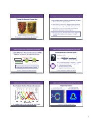
III. Near-field Scanning<br />
Optical Microscopy<br />
(NSOM)<br />
Tuning fork<br />
Voltage signal<br />
Figure 3-1. Tuning fork mechanism.<br />
Non-optical<br />
NSOM is an optical microscopy technique that takes advantage of<br />
<strong>SPM</strong> technology <strong>to</strong> enable users <strong>to</strong> work with standard optical <strong>to</strong>ols<br />
beyond the diffraction limit that normally restricts the resolution<br />
capability of such methods. NSOM works by exciting the sample with<br />
light passing through a sub-micron aperture formed at the end of a<br />
single-mode drawn optical fiber. Typically, the aperture is a few tens<br />
of nanometers in diameter. The fiber is coated with aluminum <strong>to</strong><br />
prevent light loss, thus ensuring a focused beam from the tip.<br />
As in <strong>SPM</strong>s, a probe measures the tip-sample distance and<br />
piezoelectric scanners are used <strong>to</strong> scan the sample in a defined<br />
pattern and respond <strong>to</strong> changes in the sample <strong>to</strong>pography. These two<br />
technologies make it possible <strong>to</strong> bring the aperture of the optical fiber<br />
in<strong>to</strong> the “near-field” regime and maintain that distance throughout the<br />
scanning process. In NSOM, the probe may be tuning fork-based<br />
shear-force feedback. Tuning fork technology eliminates the need for<br />
an additional feedback laser, as found in earlier NSOM designs<br />
(Figure 3-1).