A Practical Guide to SPM
A Practical Guide to SPM
A Practical Guide to SPM

You also want an ePaper? Increase the reach of your titles
YUMPU automatically turns print PDFs into web optimized ePapers that Google loves.
26<br />
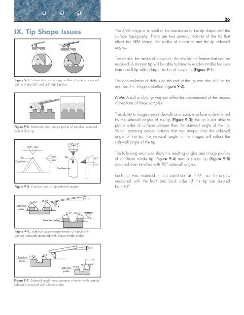
IX. Tip Shape Issues<br />
The <strong>SPM</strong> image is a result of the interaction of the tip shape with the<br />
surface <strong>to</strong>pography. There are two primary features of the tip that<br />
affect the <strong>SPM</strong> image: the radius of curvature and the tip sidewall<br />
angles.<br />
The smaller the radius of curvature, the smaller the feature that can be<br />
resolved. A sharper tip will be able <strong>to</strong> laterally resolve smaller features<br />
than a dull tip with a larger radius of curvature (Figure 9-1).<br />
Figure 9-1. Schematics and image profiles of spheres scanned<br />
with a sharp (left) and dull (right) probe.<br />
The accumulation of debris on the end of the tip can also dull the tip<br />
and result in image dis<strong>to</strong>rtion (Figure 9-2).<br />
Note: A dull or dirty tip may not affect the measurement of the vertical<br />
dimensions of these samples.<br />
Figure 9-2. Schematic and image profile of trenches scanned<br />
with a dirty tip.<br />
35.0° 35.0°<br />
17.0° 17.0°<br />
The ability <strong>to</strong> image steep sidewalls on a sample surface is determined<br />
by the sidewall angles of the tip (Figure 9-3); the tip is not able <strong>to</strong><br />
profile sides of surfaces steeper than the sidewall angle of the tip.<br />
When scanning across features that are steeper than the sidewall<br />
angle of the tip, the sidewall angle in the images will reflect the<br />
sidewall angle of the tip.<br />
Tip<br />
Cantilever<br />
35.0° Tip<br />
35.0°<br />
Cantilever<br />
25.0°<br />
10.0°<br />
The following examples show the resulting angles and image profiles<br />
of a silicon nitride tip (Figure 9-4) and a silicon tip (Figure 9-5)<br />
scanned over trenches with 90° sidewall angles.<br />
Figure 9-3. Comparison of tip sidewall angles.<br />
Each tip was mounted in the cantilever at ~10°, so the angles<br />
measured with the front and back sides of the tip are skewed<br />
by ~10°.<br />
Scan line<br />
profile<br />
45.0°<br />
65.0°<br />
10.0°<br />
55.0° 55.0°<br />
Scan line profile<br />
Figure 9-4. Sidewall angle measurements of trench with<br />
vertical sidewalls acquired with silicon nitride probe.<br />
10.0°<br />
Scan line<br />
profile<br />
55.0°<br />
90.0°<br />
Scan line<br />
profile<br />
73.0°<br />
73.0°<br />
Figure 9-5. Sidewall angle measurements of trench with vertical<br />
sidewalls acquired with silicon probe.