A Practical Guide to SPM
A Practical Guide to SPM
A Practical Guide to SPM

You also want an ePaper? Increase the reach of your titles
YUMPU automatically turns print PDFs into web optimized ePapers that Google loves.
23<br />
Aging<br />
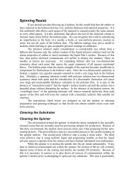
The sensitivity of piezoelectric materials decreases exponentially with<br />
operation time. Therefore, most of the change in sensitivity occurs at the<br />
beginning of a scanner’s life, as shown in Figure 7-9.<br />
Sensitivity<br />
Time<br />
Figure 7-9. Sensitivity<br />
vs. operation time.<br />
Before Veeco scanners are shipped they run approximately 48 hours<br />
in order <strong>to</strong> get past the point where sensitivity changes dramatically<br />
over short periods of time. As the scanner ages, its sensitivity will change<br />
less with time, eventually reaching the point where recalibration is<br />
seldom needed.<br />
Creep<br />
Creep is the drift of the piezo displacement after a DC offset voltage is<br />
applied <strong>to</strong> the piezo. This may occur with large changes in X and Y<br />
offsets, and when using the Frame Up and Frame Down commands<br />
when the piezo travels over most of the scan area <strong>to</strong> restart the scan.<br />
When a large offset is performed, the scanner s<strong>to</strong>ps scanning and a DC<br />
voltage is applied <strong>to</strong> the scanner <strong>to</strong> move the requested offset distance.<br />
However, the scanner does not move the full offset distance all at once.<br />
It initially moves the majority of the offset distance quickly, and then<br />
slowly moves over the remainder. The scanning resumes after a majority<br />
of the offset distance has been moved, although the scanner is still<br />
slowly moving in the direction of the offset.<br />
This slow movement of the piezo over the remainder of the offset<br />
distance once scanning has resumed results in creep. Creep appears in<br />
the image as an elongation and stretching of features in the direction of<br />
the offset for a short period of time after the offset.<br />
An example of creep is shown in Figure 7-10. The tip was scanning<br />
from <strong>to</strong>p <strong>to</strong> bot<strong>to</strong>m and an offset of 10µm in the X direction was<br />
performed near the beginning of the scan (indicated by the arrow). The<br />
slight bending of the lines that occurs directly after performing the offset<br />
is due <strong>to</strong> creep. The creep settles out by the end of the scan.<br />
Figure 7-10. Image of<br />
a calibration grating.<br />
When creep appears in an image, it will often settle out by the end of<br />
the scan and the next image may be captured. For very large offsets<br />
(>50µm), it may take longer than one scan for the creep <strong>to</strong> settle out.<br />
The creep can be reduced by offsetting beyond the desired point and<br />
then offsetting back <strong>to</strong> the desired point.<br />
Bow<br />
Because scanners are attached at one end and move the sample or tip<br />
on the other, the free end does not move in a level plane. The<br />
mechanical properties of the piezo, as well as the kinematics of motion,<br />
often result in 2 nd order or 3 rd order curvatures from an ideal plane. This<br />
is commonly called bow, which increases with scan size. The bows can<br />
be removed from a captured image by using special software.