EH12, EH17, EH25 - Small Engine Discount
EH12, EH17, EH25 - Small Engine Discount EH12, EH17, EH25 - Small Engine Discount
~ ~~ ~ ~~ ~~~ ~ I Step Part to remove - 11 12 13 14 - Governor lever, Governor rod and Governor spring Procedures (1) Unhook governor spring from speed control lever. (2) Remove governor lever from governor shaft. M6X30mm bolt and washer - - - a Ipc. (3) Detach governor lever, governor rod and rod spring from carburetor. Remarks Bolt and washer on governor lever only needs to be loosened. Carburetor I (1) Remove carburetor from intake manifold. I I Speed control lever In take manifold (1) Remove stop plate, friction plate and speed control lever. M6X30mmflangebolt --.. lpc. (I) Remove intake manifold from cylinder head. M6 flange nut .--- 2pcs. (EH12,17) M6X25mmflangebolt.... lpc. (EH12,17) M8x28rnm bolt and washer * * a . ~PCS. (EH25) ~~ ~ ~ ~~~ ~ ~ ~~~ ~ M6 FLANGE BOLT : 1 PC. -9 STOP PLATE ./a FRICTION PLATE Be careful not to lose insulator and gasket. M6 FLANGE NUT : 2 pcs(EH12.17) M6 FLANGE BOLT : 1 pc(EH12.17) GASKET M6 BOLT and WASHER : 3 pcs. /“I”. (EH25) A Tool lOmm socket wrench lOmm socket wrench lOmm, 12mm socket wrench (INSULATOR) I SPEED CONTROL LEVER ,-\ ROD SPRING GOVERNOR LEVER M6 BOLT and WASHER : 1 PC. Fig. 5-8 - 22 - .’
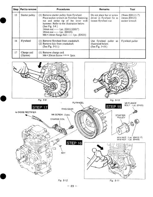
~~ ~~ Procedures Remarks Tool 15 Starter pulley (1) Remove starter pulley from flywheel. Place socket wrench on flywheel fastening nut and strike tip of the lever with hammer. Refer to the illustration below. (See Fig. 5-9.) 14mm nut lpc. (EH12,EH17) 18mm nut -.-. lpc. (EH25) 1 pc. (EH2.5) M6 X 14mm flange bolt - - Do not place bar or screw driver in flywheel fin to loosen flywheel nut. 19mm (EH12,17) 24mm (EH25) socket wrench 16 Flywheel I 17 1 Charge coil (Option) (1) Remove flywheel from crankshaft. (2) Remove key from crankshaft. (See Fig. 5-1 1 .) (1) Remove charge coil. M6 X 20mm Screw 2pcs. Use flywheel puller as illustrated below. (See Fig. 5-10.> Flywheel puller Fig. 5-9 F LYWHEEL w Fig. 5-1 0 Fig. 5-12 - 23 -
- Page 2 and 3: ROBIN ROBIN AMERICA, INC. ROBIN TO
- Page 4 and 5: " . 13-1 13-2 13-3 13-4 13-5 13-6 1
- Page 6 and 7: ~~~~ ~~ Model TY Pe Bore X Stroke P
- Page 8 and 9: 2. PERFORMANCE 2-1 MAXIMUM OUTPUT A
- Page 10 and 11: n 0 EHf7D, B (. ). for B type " kg-
- Page 12 and 13: 3. FEATURES 1. The overhead valve d
- Page 14 and 15: 4-6 CAMSHAFT ‘I’he camshaft for
- Page 16 and 17: 4-12 IGNITION SYSTEM The ignition s
- Page 18 and 19: ROCKER ARM I L - 14 -
- Page 20 and 21: 5-3 DISASSEMBLY PROCEDURES Step Par
- Page 22 and 23: ~~ I Step I Part to remove 1 Proced
- Page 24 and 25: Step Part to remove Procedures Rema
- Page 28 and 29: ~~ ~ ~~ Step 18 Part to remove 1 Pr
- Page 30 and 31: Step Part to remove 1 Procedures Re
- Page 32 and 33: Step 26 Part to remove Connecting r
- Page 34 and 35: ~~~~ Step Part to remove Procedures
- Page 36 and 37: TOP RING “N” MARK SECOND RlNC O
- Page 38 and 39: 54-5 BALANCER SHAFT (EH25 type only
- Page 40 and 41: Fig. 5-36 (2) Lubricate the oil sea
- Page 42 and 43: (2) Loosen the lock nut on the rock
- Page 44 and 45: (3) Connect the speed control lever
- Page 46 and 47: 5-5 BREAK-IN OPERATION An engine th
- Page 48 and 49: 6-3 WIRING DIAGRAM STANDARD - Ignit
- Page 50 and 51: 8. CARBURETOR 8-1 OPERATION AND CON
- Page 52 and 53: 8-2-4 MAIN SYSTEM (1) Remove the bo
- Page 54 and 55: (4) Remove the reel from the starte
- Page 56 and 57: (6) Test the operation of the recoi
- Page 58 and 59: 10-1-3 IGNlTfON SYSTEM Check the fo
- Page 60 and 61: 11. INSTALLATION Engine life, ease
- Page 62 and 63: ITEM T EH12 T EH17 Unit: mrn (in) S
- Page 64 and 65: ~~ ~~~ ~ Ring groove ITEM side clea
- Page 66 and 67: ITEM T STD EH12 Limit Unit: mrn (in
- Page 68 and 69: ~ CONNECTING ROD ITEM T STD EH25 Li
- Page 70 and 71: Unit : mm (in) CAMSHAFT ITEM STD EH
- Page 72 and 73: ITEM T STD EH25 Limit Unit: mm (in)
- Page 74 and 75: 12-3 OIL GRADE CHART I 5w I Compari
~~ ~~<br />
Procedures<br />
Remarks<br />
Tool<br />
15 Starter pulley<br />
(1) Remove starter pulley from flywheel.<br />
Place socket wrench on flywheel fastening<br />
nut and strike tip of the lever with<br />
hammer. Refer to the illustration below.<br />
(See Fig. 5-9.)<br />
14mm nut lpc. (<strong>EH12</strong>,<strong>EH17</strong>)<br />
18mm nut -.-. lpc. (<strong>EH25</strong>)<br />
1 pc. (EH2.5)<br />
M6 X 14mm flange bolt - -<br />
Do not place bar or screw<br />
driver in flywheel fin to<br />
loosen flywheel nut.<br />
19mm (<strong>EH12</strong>,17)<br />
24mm (<strong>EH25</strong>)<br />
socket wrench<br />
16 Flywheel<br />
I<br />
17 1 Charge coil<br />
(Option)<br />
(1) Remove flywheel from crankshaft.<br />
(2) Remove key from crankshaft.<br />
(See Fig. 5-1 1 .)<br />
(1) Remove charge coil.<br />
M6 X 20mm Screw<br />
2pcs.<br />
Use flywheel puller as<br />
illustrated below.<br />
(See Fig. 5-10.><br />
Flywheel puller<br />
Fig. 5-9<br />
F LYWHEEL<br />
w<br />
Fig. 5-1 0<br />
Fig. 5-12<br />
- 23 -


