Showerheads, Parts and Accessories Section - Sloan Valve Company
Showerheads, Parts and Accessories Section - Sloan Valve Company Showerheads, Parts and Accessories Section - Sloan Valve Company
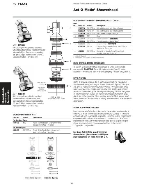
Repair Parts and Maintenance Guide Act-O-Matic ® Showerhead PARTS FOR ACT-O-MATIC ® SHOWERHEAD AC-11/AC-51 AC-51 4021000 Self-cleaning chrome plated showerhead without (less) thumb screw volume control and universal ball joint. Pressure compensating 2.5 gpm/9.4 Lpm maximum flow control. All brass construction. 1/2'' I.P.S. inlet. 1 2 Item No. Code No. Part No. Description 1. 3328026 SH-1007-A Ball Joint Coupling with Volume Control † 0328059 AC-18-AV Ball Joint Coupling less Volume Control 2. 5328010 SH-1000-A SH-3 Gasket – 24 per package 3. 0328001 SH-1 Body ‡ 4. 4328470 SH-1003-A Piston Assembly † – OBSOLETE 4328466 SH-1002-A Piston Assembly – Needle Spray † 5. 0328004 SH-2 Coupling Ring ‡ – OBSOLETE 0328005 SH-2-N Coupling Ring – Needle Spray ‡ SH-1002-A – available in SH-1008-A — 432846 SH-1008-A Repair Kit for Needle Spray Showerhead includes Items Nos. 2-5 at left. † Includes SH-3 gasket. ‡ Chrome plated. Consult factory for other available finishes. 3 FLOW CONTROL MODEL CONVERSION To convert an older Act-O-Matic showerhead to a flow control model, use repair kit SH-1008-A. Repair Kit contains gasket (item 2), piston assembly – needle spray (item 4) and coupling ring – needle spray (item 5). 4 NEEDLE SPRAY Showerheads, Parts and Accessories GROVE INDICATES SH-2-N. (NO GROOVE INDICATES OBSOLETE SH-2) AC-11 4020100 Self-cleaning chrome plated showerhead with thumb screw volume control and universal ball joint. Pressure compensating 2.5 gpm/9.4 Lpm maximum flow control. All brass construction. 1/2'' I.P.S. inlet. MODEL AC-51/AC-11 WITH VOLUME CONTROL SHOWN 5 NOTE: To properly repair an Act-O-Matic showerhead, it is important to identify needle spray part designs. Shower heads with 3 gpm (11 Lpm) or 2.5 gpm (9.4 Lpm) flow controls produced since 1985 use needle spray piston assembly and a needle spray coupling ring. Needle spray shower heads can be identified by the following: coupling ring (SH-2-N) has groove on knurled diameter; plus an “N” marked on the back of the black spray disc in the piston assembly. When repairing an Act-O-Matic shower head with a flow control it is important to identify whether the part is of the needle spray design. SLOAN ACT-O-MATIC ® MODELS In accordance with Federal and State water conservation requirements, all Sloan Act-O-Matic showerheads manufactured after January 1, 1994 are available only with an integral 2.5 gpm (9.4 Lpm) flow control. Replacement components will continue to be available for non-flow control Act-O-Matic showerhead models. Act-O-Matic showerheads rated at 3 gpm (11 Lpm) should be repaired using the components shown for the current 2.5 gpm (9.4 Lpm) models. SHOWERHEAD REPAIR KITS Code No. Part No. Description For Standard Spray 4328470 N/A Repair Kit for Standard Spray Showerhead includes Items Nos. 1-4 (below) For Needle Spray 4328466 SH-1002-A Repair Kit for Needle Spray Showerhead includes Items Nos. 1-4 (below) For Sloan Act-O-Matic model 100 series shower-heads (discontinued in 1970) use piston assembly SH-1003-A and SH-2-N. OBSOLETE 90
- Page 2 and 3: Repair Parts and Maintenance Guide
- Page 4 and 5: Repair Parts and Maintenance Guide
- Page 6 and 7: Repair Parts and Maintenance Guide
- Page 8 and 9: Repair Parts and Maintenance Guide
- Page 10 and 11: Repair Parts and Maintenance Guide
- Page 12 and 13: Repair Parts and Maintenance Guide
- Page 14 and 15: Repair Parts and Maintenance Guide
- Page 16 and 17: Repair Parts and Maintenance Guide
- Page 18 and 19: Repair Parts and Maintenance Guide
- Page 20 and 21: Repair Parts and Maintenance Guide
- Page 22 and 23: Repair Parts and Maintenance Guide
- Page 24 and 25: Repair Parts and Maintenance Guide
- Page 26 and 27: Repair Parts and Maintenance Guide
- Page 28 and 29: Repair Parts and Maintenance Guide
- Page 30 and 31: Repair Parts and Maintenance Guide
Repair <strong>Parts</strong> <strong>and</strong> Maintenance Guide<br />
Act-O-Matic ® Showerhead<br />
PARTS FOR ACT-O-MATIC ® SHOWERHEAD AC-11/AC-51<br />
AC-51 4021000<br />
Self-cleaning chrome plated showerhead<br />
without (less) thumb screw volume control <strong>and</strong><br />
universal ball joint. Pressure compensating<br />
2.5 gpm/9.4 Lpm maximum flow control. All<br />
brass construction. 1/2'' I.P.S. inlet.<br />
1<br />
2<br />
Item<br />
No. Code No. Part No. Description<br />
1. 3328026 SH-1007-A Ball Joint Coupling with Volume Control †<br />
0328059 AC-18-AV Ball Joint Coupling less Volume Control<br />
2. 5328010 SH-1000-A SH-3 Gasket – 24 per package<br />
3. 0328001 SH-1 Body ‡<br />
4. 4328470 SH-1003-A Piston Assembly † – OBSOLETE<br />
4328466 SH-1002-A Piston Assembly – Needle Spray †<br />
5. 0328004 SH-2 Coupling Ring ‡ – OBSOLETE<br />
0328005 SH-2-N Coupling Ring – Needle Spray ‡ SH-1002-A –<br />
available in SH-1008-A<br />
— 432846 SH-1008-A Repair Kit for Needle Spray Showerhead<br />
includes Items Nos. 2-5 at left.<br />
† Includes SH-3 gasket.<br />
‡ Chrome plated. Consult factory for other available finishes.<br />
3<br />
FLOW CONTROL MODEL CONVERSION<br />
To convert an older Act-O-Matic showerhead to a flow control model,<br />
use repair kit SH-1008-A. Repair Kit contains gasket (item 2), piston<br />
assembly – needle spray (item 4) <strong>and</strong> coupling ring – needle spray (item 5).<br />
4<br />
NEEDLE SPRAY<br />
<strong>Showerheads</strong>,<br />
<strong>Parts</strong> <strong>and</strong><br />
<strong>Accessories</strong><br />
GROVE INDICATES<br />
SH-2-N.<br />
(NO GROOVE<br />
INDICATES<br />
OBSOLETE SH-2)<br />
AC-11 4020100<br />
Self-cleaning chrome plated showerhead<br />
with thumb screw volume control <strong>and</strong><br />
universal ball joint. Pressure compensating<br />
2.5 gpm/9.4 Lpm maximum flow control. All<br />
brass construction. 1/2'' I.P.S. inlet.<br />
MODEL AC-51/AC-11<br />
WITH VOLUME CONTROL SHOWN<br />
5<br />
NOTE: To properly repair an Act-O-Matic showerhead, it is important to<br />
identify needle spray part designs. Shower heads with 3 gpm (11 Lpm) or<br />
2.5 gpm (9.4 Lpm) flow controls produced since 1985 use needle spray<br />
piston assembly <strong>and</strong> a needle spray coupling ring. Needle spray shower<br />
heads can be identified by the following: coupling ring (SH-2-N) has groove<br />
on knurled diameter; plus an “N” marked on the back of the black spray<br />
disc in the piston assembly. When repairing an Act-O-Matic shower head<br />
with a flow control it is important to identify whether the part is of the needle<br />
spray design.<br />
SLOAN ACT-O-MATIC ® MODELS<br />
In accordance with Federal <strong>and</strong> State water conservation requirements, all<br />
<strong>Sloan</strong> Act-O-Matic showerheads manufactured after January 1, 1994 are<br />
available only with an integral 2.5 gpm (9.4 Lpm) flow control. Replacement<br />
components will continue to be available for non-flow control Act-O-Matic<br />
showerhead models. Act-O-Matic showerheads rated at 3 gpm (11 Lpm)<br />
should be repaired using the components shown for the current<br />
2.5 gpm (9.4 Lpm) models.<br />
SHOWERHEAD REPAIR KITS<br />
Code No. Part No. Description<br />
For St<strong>and</strong>ard Spray<br />
4328470 N/A Repair Kit for St<strong>and</strong>ard Spray Showerhead<br />
includes Items Nos. 1-4 (below)<br />
For Needle Spray<br />
4328466 SH-1002-A Repair Kit for Needle Spray Showerhead<br />
includes Items Nos. 1-4 (below)<br />
For <strong>Sloan</strong> Act-O-Matic model 100 series<br />
shower-heads (discontinued in 1970) use<br />
piston assembly SH-1003-A <strong>and</strong> SH-2-N.<br />
OBSOLETE<br />
90
Repair <strong>Parts</strong> <strong>and</strong> Maintenance Guide<br />
Act-O-Matic ® Showerhead<br />
SH-1009-A REPAIR KIT FOR AC-450<br />
MODEL SHOWERHEAD INCLUDES:<br />
Item Description<br />
1. Showerhead Spray Disc Assembly<br />
2. Spray Disc O-ring<br />
3. Adjustment Screw O-ring<br />
4. Pipe Fitting O-ring<br />
5. 2.5 gpm (9.4 Lpm) Flow Control Kit<br />
Code No. 4328210, Part SH-1010-A<br />
4<br />
3<br />
ADJUSTMENT SCREW<br />
Note: Items 2, 3 <strong>and</strong> 4 are also available in<br />
O-ring replacement kit SH-1001-A.<br />
2<br />
SERVICING INSTRUCTIONS<br />
1. Remove showerhead from wall by unscrewing<br />
two (2) cap screws. Use 5/32'' allen head<br />
wrench.<br />
2. Remove adjustment screw from showerhead<br />
body.<br />
3. Remove spray disc assembly by pushing through back of<br />
showerhead body.<br />
4. Clean inside of showerhead body of all sediment <strong>and</strong> replace all<br />
O-ring seals.<br />
5. Replace (or add) flow control in pipe fitting.<br />
6. Replace spray disc assembly <strong>and</strong> reassemble showerhead in<br />
reverse order.<br />
PIPE FITTING<br />
5<br />
TO CLEAN SPRAY DISC ASSEMBLY:<br />
1. Disassemble showerhead according to<br />
servicing instructions shown above.<br />
2. Use spanner wrench or pliers to<br />
disassemble spray disc assembly<br />
(see exploded view).<br />
3. Clean sediment <strong>and</strong> debris from<br />
all components.<br />
4. Replace with repair kit<br />
Code No. 4328471,<br />
part SH-1009-A if necessary.<br />
1<br />
SPRAY DISC ASSEMBLY<br />
SPRAY DISC<br />
ASSEMBLY<br />
Item 1<br />
(see above<br />
illustration)<br />
<strong>Showerheads</strong>,<br />
<strong>Parts</strong> <strong>and</strong><br />
<strong>Accessories</strong><br />
AC-450 4024500 AC-460 4024600<br />
Institutional style self-cleaning showerhead similar <strong>Sloan</strong> Act-O-Matic<br />
institutional style models.<br />
In accordance with Federal <strong>and</strong> State water conservation requirements, all<br />
<strong>Sloan</strong> Act-O-Matic ® showerheads manufactured after January 1, 1994 are<br />
available only with an integral 2.5 gpm (9.4 Lpm) flow control. All model<br />
variations of AC-450/AC-460 Act-O-Matic showerheads can be repaired using<br />
the SH-1009-A repair kit (see above). When repairing an older AC-450 without<br />
a flow control, install the 2.5 gpm (9.4 Lpm) flow control supplied with the<br />
repair kit.<br />
When assistance is required, please contact<br />
<strong>Sloan</strong> Technical Support at: 1-888-SLOAN-14 (1-888-756-2614).<br />
SHOWERHEAD FLOW CONTROLS<br />
Code No. Part No. Description<br />
For St<strong>and</strong>ard <strong>Showerheads</strong><br />
4328285 AC-300-A B-4 4 Gallon Flow Control for Showerhead<br />
Models AC-10, AC-11, AC-51 And AC-75 – OBSOLETE<br />
4328287 AC-310-A B-3 3 Gallon Flow Control for Showerhead<br />
Models AC-10, AC-11, AC-51 And AC-75 – OBSOLETE<br />
For Institutional <strong>Showerheads</strong><br />
4328290 AC-320-A B-4 4 Gallon Flow Control for Showerhead<br />
Models AC-450 – OBSOLETE<br />
4328289 AC-325-A B-3 3 Gallon Flow Control for Showerhead<br />
Models AC-450 – OBSOLETE<br />
91
Repair <strong>Parts</strong> <strong>and</strong> Maintenance Guide<br />
Control Stop<br />
H-700 Series Bak-Chek ® control stops <strong>and</strong> replacement<br />
parts (available for 3/4” <strong>and</strong> 1” water supply inlet pipes)<br />
Replaces H-600 <strong>and</strong> H-540 Series control stops<br />
CONTROL STOP AND REPLACEMENT PARTS<br />
Code No. Part No. Description<br />
H-700 Stop, chrome plated: Screwdriver Angle Stop with H-1010-A V<strong>and</strong>al Resistant Cap<br />
Complete Stops<br />
A<br />
3308384 H-700-A 3/4” NPTF inlet for adjustable tail<br />
3308386 H-700-A 1” NPTF inlet for adjustable tail<br />
B<br />
3308385 H-700-AG 3/4” NPTF inlet for ground joint tail<br />
3308387 H-700-AG 1” NPTF inlet for ground joint tail<br />
C<br />
3308388 H-700-AW 1” Whitworth inlet for adjustable tail<br />
Repair <strong>Parts</strong><br />
3308772 H-1010-A A V<strong>and</strong>al Resistant Cap*, chrome plated<br />
0308612 H-622 B Bonnet, chrome plated<br />
3308853 H-541-ASD C Control Stop Repair Kit*<br />
<strong>Showerheads</strong>,<br />
<strong>Parts</strong> <strong>and</strong><br />
<strong>Accessories</strong><br />
H-710 Stop, chrome plated: Screwdriver Angle Stop with H-573-A Locking V<strong>and</strong>al Resistant Cap<br />
A<br />
B<br />
C<br />
Complete Stops<br />
0388025 H-710-A 3/4” NPTF inlet for adjustable tail<br />
0388022 H-710-A 1” NPTF inlet for adjustable tail<br />
0388026 H-710-AG 3/4” NPTF inlet for ground joint tail<br />
0388024 H-710-AG 1” NPTF inlet for ground joint tail<br />
0388037 H-710-AW 1” Whitworth inlet for adjustable tail<br />
0388062 H-710-AAR 1” BSP British St<strong>and</strong>ard Pipe inlet for adjustable tail<br />
0388043 NH-710-A 1” NPTF inlet for adjustable tail (Naval brass)<br />
0388048 NH-710-AG 3/4” NPTF inlet for ground joint tail (Naval brass)<br />
0388058 NH-710-AG 1” NPTF inlet for ground joint tail (Naval brass)<br />
0388042 NH-710-AW 1” Whitworth inlet for adjustable tail (Naval brass)<br />
0388045 NH-710-AGW 1” Whitworth inlet for ground joint tail (Naval brass)<br />
0388044 NH-710-AGS 1” NPSM inlet for ground joint tail (Naval brass)<br />
Repair <strong>Parts</strong><br />
3308840 H-573-A A Locking V<strong>and</strong>al Resistant Cap*, chrome plated<br />
0308612 H-622 B Bonnet, chrome plated<br />
3308853 H-541-ASD C Control Stop Repair Kit*<br />
H-720 Stop, chrome plated: Screwdriver Angle Stop with H-574 Short bumper Cap (-YO Variation)<br />
A<br />
B<br />
C<br />
Complete Stops<br />
0388034 H-720-A 1” NPTF inlet for adjustable tail<br />
0388033 H-720-AG 1” NPTF inlet for ground joint tail<br />
0388038 H-720-AW 1” Whitworth inlet for adjustable tail<br />
Repair <strong>Parts</strong><br />
3308866 H-574 A Stop Cap with Seat Bumper*, chrome plated<br />
0308612 H-622 B Bonnet, chrome plated<br />
3308853 H-541-ASD C Control Stop Repair Kit*<br />
*Refer to page 95 for diagrams of our Stop Caps <strong>and</strong> page 96 for the components supplied in our Control Stop<br />
Repair Kits.<br />
92
Repair <strong>Parts</strong> <strong>and</strong> Maintenance Guide<br />
Control Stop<br />
CONTROL STOP AND REPLACEMENT PARTS<br />
Code No. Part No. Description<br />
H-725 Stop, chrome plated: Screwdriver Angle Stop with H-576 Extended Bumper Cap (-YG Variation)<br />
Complete Stops<br />
A<br />
B<br />
0388035<br />
0388039<br />
H-725-A<br />
H-725-AW<br />
1” NPTF inlet for adjustable tail<br />
1” Whitworth inlet for adjustable tail<br />
0388057<br />
0388047<br />
H-725-AG<br />
NH-725-AGW<br />
1” NPTF inlet for ground joint tail<br />
1” Whitworth inlet for ground joint tail (Naval brass)<br />
Repair <strong>Parts</strong><br />
C<br />
3308867 H-576 A Stop Cap with Extended Seat Bumper*, chrome<br />
plated<br />
0308612 H-622 B Bonnet, chrome plated<br />
3308853 H-541-ASD C Control Stop Repair Kit*<br />
H-730 Stop, rough brass: Concealed Wheel H<strong>and</strong>le Angle Stop<br />
A<br />
B<br />
C<br />
H-735 Stop, chrome plated: Exposed Wheel H<strong>and</strong>le Angle Stop<br />
A<br />
B<br />
C<br />
Complete Stops<br />
0388011 H-730-A 3/4” NPTF inlet for adjustable tail<br />
0388010 H-730-A 1” NPTF inlet for adjustable tail<br />
0388014 H-730-AG 3/4” NPTF inlet for ground joint tail<br />
0388013 H-730-AG 1” NPTF inlet for ground joint tail<br />
0388012 H-730-AW 1” Whitworth inlet for adjustable tail<br />
0388056 NH-730-AG 3/4” NPTF inlet for ground joint tail (Naval brass)<br />
0388017 NH-730-AG 1” NPTF inlet for ground joint tail (Naval brass)<br />
0388041 NH-730-AW 1” Whitworth inlet for adjustable tail (Naval brass)<br />
0388046 NH-730-AGW 1” Whitworth inlet for ground joint tail (Naval brass)<br />
Repair <strong>Parts</strong><br />
3308872 H-1011-A A Concealed Wheel H<strong>and</strong>le Repair Kit*<br />
0208083 H-623 B Bonnet, rough brass<br />
3308860 H-1006-A C Control Stop Repair Kit*<br />
Complete Stops<br />
0388007 H-735-A 3/4” NPTF inlet for adjustable tail<br />
0388006 H-735-A 1” NPTF inlet for adjustable tail<br />
0388009 H-735-AG 3/4” NPTF inlet for ground joint tail<br />
0388008 H-735-AG 1” NPTF inlet for ground joint tail<br />
Repair <strong>Parts</strong><br />
3308060 H-1002-A A Exposed Wheel H<strong>and</strong>le Repair Kit*<br />
0308615 H-623 B Bonnet, chrome plated<br />
3308855 H-541-AWH C Control Stop Repair Kit*<br />
*Refer to page 95 for diagrams of our Stop Caps <strong>and</strong> page 96 for the components supplied in our<br />
Control Stop Repair Kits.<br />
<strong>Showerheads</strong>,<br />
<strong>Parts</strong> <strong>and</strong><br />
<strong>Accessories</strong><br />
93
Repair <strong>Parts</strong> <strong>and</strong> Maintenance Guide<br />
Control Stop<br />
CONTROL STOP AND REPLACEMENT PARTS<br />
Code No. Part No. Description<br />
H-740 Stop, chrome plated: Screwdriver Angle Stop with H-37 Cap (Regal ® <strong>Valve</strong> Stop) – OBSOLETE<br />
H-790 Stop, chrome plated: Screwdriver Angle Stop with V<strong>and</strong>al Resistant Cap (for Regal or Regal XL <strong>Valve</strong> Stop)<br />
Complete Stops For Regal ® flushometers<br />
H-790<br />
A1<br />
A2 0388031 H-740-A 3/4” NPTF inlet for adjustable tail – OBSOLETE<br />
B<br />
0388029 H-740-A 1” NPTF inlet for adjustable tail – OBSOLETE<br />
0388040 H-740-AG 3/4” NPTF inlet for ground joint tail – OBSOLETE<br />
0388028 H-740-AG 1” NPTF inlet for ground joint tail – OBSOLETE<br />
C<br />
Complete Stops For Regal ® “XL” flushometers<br />
0388064 H-790-A 3/4” NPTF inlet for adjustable tail<br />
0388065 H-790-A 1” NPTF inlet for adjustable tail<br />
0388068 H-790-AG 3/4” NPTF inlet for ground joint tail<br />
H-740<br />
0388067 H-790-AG 1” NPTF inlet for ground joint tail<br />
Repair <strong>Parts</strong><br />
5388002 H-538 A1 Hole Plug<br />
OBSOLETE<br />
5388001 H-1012-A A2 V<strong>and</strong>al Resistant Socket Cap*, chrome plated with set<br />
screw, for Regal “XL” flushometer – 6 per package<br />
0308612 H-622 B Bonnet, chrome plated<br />
3308853 H-541-ASD C Control Stop Repair Kit*<br />
<strong>Showerheads</strong>,<br />
<strong>Parts</strong> <strong>and</strong><br />
<strong>Accessories</strong><br />
H-745 Stop, chrome plated: Screwdriver Angle Stop with J-2/J-7 Bumper (for Regal ® <strong>Valve</strong> Stop) (-YO/-YG Variations) – OBSOLETE<br />
Complete Stops<br />
A<br />
0388035 H-725-A 1” NPTF inlet for adjustable tail<br />
Repair <strong>Parts</strong><br />
B<br />
5310034 J-2/J-7 A Cap*, chrome plated – 6 per package – OBSOLETE<br />
0308991 H-639 B Bonnet, chrome plated – OBSOLETE<br />
C<br />
3308853 H-541-ASD C Control Stop Repair Kit* – OBSOLETE<br />
H-750 Stop, chrome plated: Screwdriver Straight Stop with H-1010-A V<strong>and</strong>al Resistant Cap<br />
Complete Stops<br />
A<br />
3308389 H-750-AG 1” NPTF inlet for ground joint tail<br />
Repair <strong>Parts</strong><br />
B<br />
3308772 H-1010-A A V<strong>and</strong>al Resistant Cap*, chrome plated<br />
0308612 H-622 B Bonnet, chrome plated<br />
C<br />
3308853 H-541-ASD C Control Stop Repair Kit*<br />
H-760 Stop, chrome plated: Screwdriver Straight Stop with H-573-A Locking V<strong>and</strong>al Resistant Cap<br />
Complete Stops<br />
A<br />
0388023 H-760-AG 1” NPTF inlet for ground joint tail<br />
B<br />
Repair <strong>Parts</strong><br />
0308738 H-573-A A Locking V<strong>and</strong>al Resistant Cap*, chrome plated<br />
C<br />
0308612 H-622 B Bonnet, chrome plated<br />
3308853 H-541-ASD C Control Stop Repair Kit*<br />
*Refer to page 95 for diagrams of our Stop Caps <strong>and</strong> page 96 for the components supplied in our<br />
Control Stop Repair Kits.<br />
94
Repair <strong>Parts</strong> <strong>and</strong> Maintenance Guide<br />
Control Stop<br />
CONTROL STOP AND REPLACEMENT PARTS<br />
Code No. Part No. Description<br />
H-770 Stop, rough brass: Concealed Wheel H<strong>and</strong>le Straight Stop<br />
A<br />
B<br />
C<br />
Complete Stops<br />
0388030 H-770-AG 1” NPTF inlet for ground joint tail<br />
Repair <strong>Parts</strong><br />
3308872 H-1011-A A Concealed Wheel H<strong>and</strong>le Repair Kit*<br />
0208083 H-623 B Bonnet, rough brass<br />
3308860 H-1006-A C Control Stop Repair Kit*<br />
H-775 Stop, chrome plated: Exposed Wheel H<strong>and</strong>le Straight Stop<br />
A<br />
B<br />
C<br />
Complete Stops<br />
0388036 H-775-AG 1” NPTF inlet for ground joint tail<br />
Repair <strong>Parts</strong><br />
3308060 H-1002-A A Exposed Wheel H<strong>and</strong>le Repair Kit*<br />
0308615 H-623 B Bonnet, chrome plated<br />
3308855 H-541-AWH C Control Stop Repair Kit*<br />
H-780 Stop, chrome plated: Screwdriver Straight Stop with H-37 Cap (Regal ® <strong>Valve</strong> Stop) <strong>and</strong><br />
H-795 Stop, chrome plated: Screwdriver Straight Stop with V<strong>and</strong>al Resistant Cap (for Regal or Regal XL <strong>Valve</strong> Stop)<br />
A<br />
B<br />
C<br />
Complete Stops For Regal ® flushometers<br />
0388027 H-780-AG 1” NPTF inlet for ground joint tail – OBSOLETE<br />
Complete Stops For Regal ® “XL” flushometers<br />
0388079 H-795-AG 1” NPTF inlet for ground joint tail<br />
Repair <strong>Parts</strong><br />
5388001 H-1012-A A V<strong>and</strong>al Resistant Socket Cap*, chrome plated with set<br />
screw, for Regal “XL” flushometer – 6 per package<br />
For H-790 Stop, refer to information shown for H-740 <strong>and</strong> H-790 Stops<br />
For H-795 Stop, refer to information shown for H-780 <strong>and</strong> H-795 Stops<br />
0308991 H-639 B Bonnet, chrome plated<br />
3308853 H-541-ASD C Control Stop Repair Kit*<br />
<strong>Showerheads</strong>,<br />
<strong>Parts</strong> <strong>and</strong><br />
<strong>Accessories</strong><br />
CONTROL STOP AND REPLACEMENT PARTS FOR H-540, H-600 AND H-700 SERIES CONTROL STOPS<br />
Replacement Stop Caps for Screwdriver Control Stops for H-540, H-600, <strong>and</strong> H-700 Series Control Stops<br />
For 1” H-600 <strong>and</strong> H-700 Series Stops <strong>and</strong> 3/4” H-700 Series Stops<br />
Item<br />
No. Code No. Part No. Description<br />
C.<br />
A.<br />
B.<br />
D<br />
A. 3308772 H-1010-A V<strong>and</strong>al Resistant Stop Cap, chrome plated,<br />
with Sleeve<br />
5308954 H-628 Plastic Sleeve only – 6 per package<br />
B. 3308840 H-573-A Locking V<strong>and</strong>al Resistant Stop Cap, chrome<br />
plated<br />
E.<br />
F.<br />
C. 3308866 H-574 Stop Cap, chrome plated with Seat<br />
Bumper (-YO)<br />
D. 3308867 H-576 Stop Cap, chrome plated with Extended<br />
Seat Bumper (-YG)<br />
For 3/4” H-600 Series Stops<br />
E. 3308790 H-1009-A V<strong>and</strong>al Resistant Stop Cap, chrome plated,<br />
G.<br />
H. I.<br />
with Sleeve <strong>and</strong> 3/4” Bonnet<br />
5308952 H-614 Plastic Sleeve only – 6 per package<br />
F. 0308848 H-582 Stop Cap, chrome plated<br />
For all H-40, H-440, H-540 <strong>and</strong> H-740 Series Stops<br />
G. 5388001 H-1012-A V<strong>and</strong>al Resistant Stop Cap with set screw,<br />
chrome plated – 6 per package<br />
H. 5310034 J-2/J-7 Stop Cap, chrome plated with Seat Bumper<br />
– 6 per package – OBSOLETE<br />
. I. 5388002 H-528 Hole Plug<br />
95
Repair <strong>Parts</strong> <strong>and</strong> Maintenance Guide<br />
Control Stop<br />
CONTROL STOP AND REPLACEMENT PARTS FOR H-540, H-600 AND H-700 SERIES CONTROL STOPS<br />
Code No. Part No. Description<br />
Screwdriver Control Stop Repair Kits<br />
BONNET<br />
SEAT<br />
CONTROL STOP REPAIR KIT<br />
Complete Repair Kits<br />
3308853 H-541-ASD For 1” H-540, H-600 <strong>and</strong> H-700 Series Stops <strong>and</strong> 3/4”<br />
H-700 Series Stops<br />
3308856 H-543-ASD For 3/4” H-540 <strong>and</strong> H-600 Series Stops<br />
Bonnets<br />
0308612 H-622 For 1” H-600 <strong>and</strong> H-700 Series Stops <strong>and</strong> 3/4” H-700<br />
Series Stops<br />
0308991 H-639 For 1” H-540 <strong>and</strong> H-740 Series Stops <strong>and</strong> 3/4” H-740<br />
Series Stops<br />
0308843 H-577 For 3/4” H-600 Series Stops – OBSOLETE<br />
0308601 H-538 For 3/4” H-540 Series Stops – OBSOLETE<br />
Seat only – 6 per package<br />
5308850 H-584 For 1” H-540, H-600 <strong>and</strong> H-700 Series Stops <strong>and</strong> 3/4”<br />
H-700 Series Stops<br />
5308836 H-569 For 3/4” H-540 <strong>and</strong> H-600 Series Stops<br />
<strong>Showerheads</strong>,<br />
<strong>Parts</strong> <strong>and</strong><br />
<strong>Accessories</strong><br />
Concealed Wheel H<strong>and</strong>le Control Stop Repair Kits – Note: Repair Kit includes H-1011-A Wheel H<strong>and</strong>le Repair Kit<br />
Complete Repair Kits<br />
3308860 H-1006-A For 1” H-540, H-600 <strong>and</strong> H-700 WH Series Stops <strong>and</strong><br />
3/4” H-700 WH Series Stops<br />
WHEEL HANDLE REPAIR KIT*<br />
3308859 H-1007-A For 3/4” H-540 <strong>and</strong> H-600 Series Stops<br />
BONNET<br />
SEAT<br />
CONTROL STOP REPAIR KIT<br />
Wheel H<strong>and</strong>le Repair Kit — Note: Repair Kit includes h<strong>and</strong>le,<br />
screw <strong>and</strong> lockwasher<br />
3308872 H-1011-A For all Concealed Wheel H<strong>and</strong>le Stops<br />
Bonnets<br />
0208083 H-623 For 1” H-540, H-600 <strong>and</strong> H-700 WH Series Stops <strong>and</strong><br />
3/4” H-700 Series Stops<br />
0308705 H-561 For 3/4” H-540, H-600 Series Stops – OBSOLETE<br />
Seat only – 6 per package<br />
5308850 H-584 For 1” H-540, H-600 <strong>and</strong> H-700 WH Series Stops <strong>and</strong><br />
3/4” H-700 WH Series Stops<br />
5308836 H-569 For 3/4” H-540 <strong>and</strong> H-600 Series Stops<br />
NOTE: H-540 <strong>and</strong> H-600 Series concealed wheel h<strong>and</strong>le stops made prior to 1993 featured a design identical to<br />
the exposed wheel h<strong>and</strong>le design. These stops can be repaired using an exposed wheel h<strong>and</strong>le repair kit or<br />
converted to the current design by using a concealed wheel h<strong>and</strong>le repair kit.<br />
Exposed Wheel H<strong>and</strong>le Control Stop Repair Kits<br />
WHEEL HANDLE REPAIR KIT<br />
BONNET<br />
CONTROL STOP REPAIR KIT<br />
SEAT<br />
Complete Repair Kits<br />
3308855 H-541-AWH For 1” H-540, H-600 <strong>and</strong> H-700 WH Series Stops <strong>and</strong><br />
3/4” H-700 Series Stops<br />
3308858 H-543-AWH For 3/4” H-540 <strong>and</strong> H-600 Series Stops<br />
Wheel H<strong>and</strong>le Repair Kit — Note: Repair Kit includes h<strong>and</strong>le, washer,<br />
screw <strong>and</strong> lockwasher<br />
3308060 H-1002-A For all Exposed Wheel H<strong>and</strong>le Stops<br />
5308059 H-1003-A Screw <strong>and</strong> Lockwasher only – 12 per package<br />
Bonnets<br />
0308615 H-623 For 1” H-540, H-600 <strong>and</strong> H-700 WH Series Stops <strong>and</strong><br />
3/4” H-700 Series Stops<br />
0308705 H-561 For 3/4” H-540 <strong>and</strong> H-600 Series Stops – OBSOLETE<br />
Seat only – 6 per package<br />
5308850 H-584 For 1” H-540, H-600 <strong>and</strong> H-700 WH Series Stops <strong>and</strong><br />
3/4” H-700 WH Series Stops<br />
5308836 H-569 For 3/4” H-540 <strong>and</strong> H-600 Series Stops<br />
NOTE: 1” <strong>and</strong> 3/4” H-700 Series stops use “common stop” repair kits. 1” <strong>and</strong> 3/4” H-540 <strong>and</strong> H-600 Series stops<br />
use stop repair kits unique to each size. See the “common stop” on page 99 for more details.<br />
96
Repair <strong>Parts</strong> <strong>and</strong> Maintenance Guide<br />
Control Stop<br />
CONTROL STOP AND REPLACEMENT PARTS FOR OLDER CONTROL STOPS<br />
Code No. Part No. Description<br />
H-10-A 1” Screwdriver Angle Stop, (also fits H-15-A 1” Screwdriver Straight Stop) — used from 1920’s through 1940’s<br />
5308077 H-12 Packing only – 12 per package<br />
— — Bonnet no longer available<br />
H-10-A 1” Wheel H<strong>and</strong>le Angle Stop (also fits H-15-A 1” Wheel H<strong>and</strong>le Straight Stop) — Used from 1920’s through 1940’s<br />
5308077 H-12 Packing only – 12 per package<br />
— — Bonnet no longer available<br />
H-20-A 1/2” <strong>and</strong> 3/4” Screwdriver Angle Stop (also fits H-30-A Screwdriver Straight Stop) — Used from 1920’s through 1950’s<br />
5308077 H-12 Packing only – 12 per package<br />
— — Bonnet no longer available<br />
H-20-A 1/2” <strong>and</strong> 3/4” Wheel H<strong>and</strong>le Angle Stop (also fits H-30-A Wheel H<strong>and</strong>le Straight Stop) — Used from 1920’s through 1950’s<br />
5308077 H-12 Packing only – 12 per package<br />
— — Bonnet no longer available<br />
<strong>Showerheads</strong>,<br />
<strong>Parts</strong> <strong>and</strong><br />
<strong>Accessories</strong><br />
H-40-A 3/4” <strong>and</strong> 1” Screwdriver Angle Stop (also fits H-45-A Screwdriver Straight Stop) — Used from 1930’s through 1960’s<br />
3308277 H-47-A-SD Repair kit includes packing ring, key socket, lock shield,<br />
retaining ring, screw assembly, <strong>and</strong> packing<br />
0308176 H-39-A-SD Bonnet assembly repair kit includes a bonnet assembled<br />
with packing ring, key socket, retaining ring, screw<br />
assembly, <strong>and</strong> packing plus our H-37 V<strong>and</strong>al Resistant<br />
Stop Cap that replaces the lock shield<br />
5308077 H-12 Packing only – 12 per package<br />
0308167 H-39 Bonnet Only<br />
H-40-A 3/4” <strong>and</strong> 1” Wheel H<strong>and</strong>le Angle Stop (also fits H-45-A Wheel H<strong>and</strong>le Straight Stop) — Used from 1930’s through 1960’s<br />
3308278 H-47-A-WH Repair kit includes packing ring, screw, wheel h<strong>and</strong>le,<br />
key stem, gl<strong>and</strong> for wheel h<strong>and</strong>le, retaining gl<strong>and</strong>, screw<br />
assembly, washer <strong>and</strong> packing<br />
0308175 H-39-A-WH Bonnet assembly repair kit includes a bonnet assembled<br />
with packing ring, screw, wheel h<strong>and</strong>le, key stem, gl<strong>and</strong><br />
for wheel h<strong>and</strong>le, retaining gl<strong>and</strong>, screw assembly,<br />
washer <strong>and</strong> packing<br />
5308077 H-12 Packing only – 12 per package<br />
0308170 H-39 Bonnet Only<br />
97
Repair <strong>Parts</strong> <strong>and</strong> Maintenance Guide<br />
Control Stop<br />
CONTROL STOP AND REPLACEMENT PARTS<br />
Code No. Part No. Description<br />
H-340-A 3/4” <strong>and</strong> 1” Screwdriver <strong>and</strong> Wheel H<strong>and</strong>le Angle Stops — Used from 1940’s through 1950’s<br />
The only replacement part available for this stop is the rubber plug.<br />
0308433 H-382-A Rubber Plug<br />
H-440-A 3/4” Screwdriver Angle Stop — Used from 1950’s through 1960’s<br />
3308442 H-484-A-SD Repair kit includes lock shield, packing, key stem, rubber<br />
plug, <strong>and</strong> packing ring<br />
0308432 H-439-AU Bonnet assembly repair kit includes a bonnet assembled<br />
with packing, key stem, rubber plug, <strong>and</strong> packing ring<br />
plus our H-37 V<strong>and</strong>al Resistant Stop Cap that replaces<br />
the lock shield<br />
0308434 H-439 Bonnet<br />
0308490 H-484-A Rubber Plug<br />
5308077 H-12 Packing only – 12 per package<br />
<strong>Showerheads</strong>,<br />
<strong>Parts</strong> <strong>and</strong><br />
<strong>Accessories</strong><br />
H-440-A 3/4” Wheel H<strong>and</strong>le Angle Stop — Used from 1950’s through 1960’s<br />
0308435 H-439 Bonnet<br />
0308490 H-484-A Rubber Plug<br />
5308077 H-12 Packing only – 12 per package<br />
H-440-A 1” Screwdriver Angle Stop (also fits H-445-A Screwdriver Straight Stop) — Used from 1950’s through 1960’s<br />
3308453 H-482-A-SD Repair kit includes lock shield, packing, key stem, rubber<br />
plug, <strong>and</strong> packing ring<br />
0308428 H-439-A Bonnet assembly repair kit includes a bonnet assembled<br />
with packing ring, key socket, retaining ring, screw<br />
assembly, <strong>and</strong> packing plus our H-37 V<strong>and</strong>al Resistant<br />
Stop Cap that replaces the lock shield<br />
0308434 H-439 Bonnet<br />
0308489 H-482-A Rubber Plug<br />
5308077 H-12 Packing only – 12 per package<br />
H-440-A 1” Wheel H<strong>and</strong>le Angle Stop (also fits H-445-A Wheel H<strong>and</strong>le Straight Stop) — Used from 1950’s through 1960’s<br />
0308435 H-439 Bonnet<br />
0308489 H-482-A Rubber Plug<br />
5308077 H-12 Packing only – 12 per package<br />
NOTE: H-440 Series control stops were used with <strong>Sloan</strong>’s “Quiet Flush” flushometer models.<br />
NOTE: All obsolete control stops are for ground joint tailpiece connections.<br />
NOTE: <strong>Sloan</strong> <strong>Valve</strong> <strong>Company</strong> has made other stops up to 1964. If you have an older stop that is not listed on these<br />
two pages, the repair parts are obsolete. Prior to 1964, all stops were ground joint connections; the H-700-AG<br />
series stops, 3/4” <strong>and</strong> 1” angle stops, <strong>and</strong> 1” straight stops, are the current replacement.<br />
98
Repair <strong>Parts</strong> <strong>and</strong> Maintenance Guide<br />
Control Stop<br />
THE “COMMON STOP”<br />
In 1996, <strong>Sloan</strong> began using the H-700 series of control stops with all<br />
flushometers. This “common stop” offers 3/4” <strong>and</strong> 1” supply inlet size<br />
options, yet uses a single repair kit for both urinal <strong>and</strong> water closet stops.<br />
This change primarily affects the H-700 series 3/4” stops, which now use<br />
the same repair kit as 1” stops. Repair kits for the smaller H-540 <strong>and</strong> H-600<br />
3/4” stops remain available <strong>and</strong> are included in this section.<br />
The “common stop” body offers precise control over flow rates delivered<br />
through the valve. This feature is important, especially for 1-gallon urinal<br />
designs. This finite flow adjustment makes the difference between a proper<br />
flush <strong>and</strong> an ineffective flush that splashes <strong>and</strong> spills.<br />
The “common stop” internal components are interchangeable with their<br />
counterparts in older H-600 <strong>and</strong> H-540 stops. The distinctively contoured<br />
seat plug in the “common stop” allows a finer flow rate adjustment similar to<br />
that of a needle valve. Unlike natural rubber components that can be<br />
destroyed by water treatment products, our synthetic Permex rubber seat<br />
plugs resist the effects of chloramines. Our stop spring, formerly brass, is<br />
now constructed of stainless steel. This helps prevent corrosion from the<br />
increasingly aggressive water supplies we see today.<br />
All complete “common stops” now have bonnets stamped with an H-700<br />
series number. Both exposed <strong>and</strong> concealed wheel h<strong>and</strong>le stops are<br />
stamped H-700-WH series. The H-740 <strong>and</strong> H-780 stops that replace the<br />
H-540 series stops used with Regal valves are stamped H-740 series.<br />
CONTROL STOP DESIGNS<br />
Supply Inlets<br />
<strong>Sloan</strong> supplies control stops in two basic inlet sizes:<br />
1. 3/4” NPTF — For most urinal flushometers<br />
2. 1” NPTF — For all water closet flushometers <strong>and</strong> blow-out<br />
urinal flushometers<br />
Control stops are also available in some models with the following inlets for<br />
specialized <strong>and</strong> export applications:<br />
1. 1” Whitworth thread<br />
2. 1” BSP British St<strong>and</strong>ard Pipe inlet<br />
3. 1” NSPM Straight thread — for use with shipboard Sil-Braz fittings<br />
GENERAL INSTALLATION INSTRUCTIONS<br />
Install the <strong>Sloan</strong> Bak-Chek ® control stop to water supply line with outlet<br />
positioned as required. Tighten the control stop coupling with a wrench.<br />
SUPPLY FLANGE<br />
SET SCREW<br />
(8-32 X 5/8)<br />
IRON PIPE NIPPLE OR<br />
COPPER PIPE WITH SWEAT<br />
SOLDER ADAPTER<br />
COVERING TUBE<br />
BAK-CHEK ®<br />
CONTROL STOP<br />
CONTROL STOP ADJUSTMENT<br />
After installation or service, readjust the control stop to meet the flow rate<br />
required for the proper cleansing of the fixture. Open the control stop<br />
COUNTERCLOCKWISE one full turn from the closed position. Activate<br />
flushometer.<br />
Adjust control stop after each flush until the rate of flow delivered properly<br />
cleanses the fixture. Turn the control stop adjustment screw (or wheel<br />
h<strong>and</strong>le) COUNTERCLOCKWISE to increase the flow rate or CLOCKWISE to<br />
decrease the flow rate.<br />
TURN COUNTERCLOCKWISE<br />
TO OPEN<br />
TURN CLOCKWISE<br />
TO CLOSE<br />
<strong>Showerheads</strong>,<br />
<strong>Parts</strong> <strong>and</strong><br />
<strong>Accessories</strong><br />
Tailpiece Connections<br />
The majority of flushometers supplied by <strong>Sloan</strong> since 1964 feature an<br />
adjustable tailpiece. Connection of the valve tailpiece to the control stop is<br />
made with a sliding O-ring seal.<br />
Older valves (produced before 1964), <strong>and</strong> valves furnished for salt-water<br />
installations, <strong>and</strong> all straight stops utilized a metal-to-metal ground joint (GJ)<br />
connection.<br />
When replacing an older stop, it is important to note which type of stop<br />
connection is required.<br />
Stops for use with salt water must be made from Naval brass.<br />
Important: A <strong>Sloan</strong> flushometer is engineered for quiet operation. Excessive<br />
water flow creates noise, while too little water flow may not satisfy the<br />
needs of the fixture. Proper adjustment is made when the plumbing fixture is<br />
cleansed after each flush without splashing water out from the lip AND a<br />
quiet flushing cycle is achieved.<br />
The control stop should never be opened to the point where the flow from<br />
the valve exceeds the flow capability of the fixture. In the event of a valve<br />
failure, the fixture must be able to accommodate a continuous flow from<br />
the valve.<br />
MAINTENANCE AND CLEANING<br />
Control stops have moving parts that may wear over time. Deterioration of<br />
rubber parts may result in an incomplete seal. If you can not shut off the<br />
stop completely, or if leakage is visible at the adjustment screw, order one of<br />
our control stop repair kits <strong>and</strong> rebuild the control stop.<br />
DO NOT use abrasive or chemical cleaners to clean flushometers. These<br />
cleaners may dull the luster <strong>and</strong> attack the chrome or special decorative<br />
finishes. Use ONLY mild soap <strong>and</strong> water, <strong>and</strong> then wipe dry with a clean<br />
cloth or towel. While cleaning the bathroom tile, protect the flushometer<br />
from any splattering of cleaner. Acids <strong>and</strong> cleaning fluids can discolor or<br />
remove chrome plating.<br />
99
Repair <strong>Parts</strong> <strong>and</strong> Maintenance Guide<br />
Tailpiece<br />
TAILPIECES<br />
H-551-A ADJUSTABLE TAILPIECE CONNECTION<br />
H-551-A<br />
The tailpiece is the connection between<br />
the valve body <strong>and</strong> the control stop.<br />
<strong>Sloan</strong> adjustable <strong>and</strong> ground joint<br />
tailpieces are threaded into the valve<br />
body at the factory. <strong>Sloan</strong> tailpieces<br />
are available in a variety of lengths to<br />
accommodate installation rough-in errors<br />
<strong>and</strong> unique installation requirements.<br />
<strong>Sloan</strong> flushometer br<strong>and</strong>s feature three types of tailpiece connections:<br />
H-551 ADJUSTABLE<br />
TAILPIECE<br />
H-5 GROUND JOINT<br />
TAILPIECE<br />
H-130-A ADJUSTABLE<br />
GROUND JOINT TAILPIECE<br />
The majority of flushometers supplied by <strong>Sloan</strong> since 1964 feature the<br />
H-551-A adjustable tailpiece. The valve tailpiece connects to the control stop<br />
with a sliding O-ring seal. The H-551-A adjustable tailpiece st<strong>and</strong>ard length<br />
is 2-1/16" (54 mm). This is designed for a st<strong>and</strong>ard flushometer installation<br />
in which the distance between the centerline of the valve <strong>and</strong><br />
the centerline of the water supply inlet is 4-3/4" (121 mm). The adjustable<br />
tailpiece allows for a variance of ±1/2" (13 mm) from this nominal<br />
dimension.<br />
<strong>Showerheads</strong>,<br />
<strong>Parts</strong> <strong>and</strong><br />
<strong>Accessories</strong><br />
TAILPIECE REPLACEMENT<br />
H-530 TAILPIECE REMOVAL BAR<br />
0334014<br />
<strong>Sloan</strong> adjustable <strong>and</strong> ground<br />
joint tailpieces are assembled<br />
into the valve body using a<br />
pipe thread. Significant force<br />
is used to drive the tailpiece<br />
into the valve body. As such,<br />
removal of the old tailpiece<br />
may be difficult.<br />
For replacement, we<br />
recommend using the H-530 tailpiece removal bar (Code No. 0334014).<br />
Remove the flushometer cover <strong>and</strong> interior parts. Secure the tailpiece<br />
removal bar vertically in a vice. Place the flushometer tailpiece over the bar.<br />
The cast lugs inside the tailpiece will catch on the bar. Insert a length of<br />
3/4" pipe into the barrel of the valve body. Unscrew tailpiece from<br />
valve body.<br />
Assemble the new tailpiece into the valve body in the reverse manner. Use<br />
teflon tape (or pipe sealant) on tailpiece pipe threads. Ensure that both the<br />
coupling <strong>and</strong> the locking ring (adjustable tailpiece only) are on the tailpiece<br />
before tightening the assembly. Do NOT use sealant on the first few threads<br />
of the tailpiece.<br />
H-551-A<br />
Item<br />
No. Code No. Part No. Description<br />
1. 0308676 H-550 Coupling CP<br />
0308690 H-550 Coupling RB<br />
2. 5308381 H-552 Locking Ring – 12 per package<br />
3. 5308696 H-553 O-Ring – 24 per package<br />
4. 0308801 H-551-A 2-1/16" (53 mm) Tailpiece Assembly † CP<br />
0308802 H-551-A 2-1/16" (53 mm) Tailpiece Assembly † RB<br />
0308803 H-551-A 3-1/16" (78 mm) Tailpiece Assembly † CP<br />
0308805 H-551-A 4-1/16" (103 mm) Tailpiece Assembly † CP<br />
0308807 H-551-A 5-1/16" (129 mm) Tailpiece Assembly † CP<br />
0308809 H-551-A 6-1/16" (154 mm) Tailpiece Assembly † CP<br />
† Each tailpiece assembly includes an H-553 O-Ring <strong>and</strong> an H-552 locking ring.<br />
Abbreviations: CP: chrome plated; RB: rough brass<br />
<strong>Sloan</strong> <strong>Valve</strong> <strong>Company</strong> can also provide products not shown in our current catalog.<br />
For our special finishes, consult factory for part numbers.<br />
100
Repair <strong>Parts</strong> <strong>and</strong> Maintenance Guide<br />
Tailpiece<br />
H-5 GROUND JOINT TAILPIECE CONNECTION<br />
Older valves (prior to 1964), valves furnished for saltwater<br />
installations, <strong>and</strong> all <strong>Sloan</strong> flushometers furnished<br />
with straight stops use a metal-to-metal ground joint<br />
(GJ) tailpiece connection. The st<strong>and</strong>ard length of the<br />
H-5 tailpiece is 1-3/4" (44 mm) for a st<strong>and</strong>ard 4-3/4"<br />
(121 mm) rough-in dimension; other lengths are<br />
available in 1/4" (6 mm) increments.<br />
The ground joint tailpiece connection<br />
cannot be adjusted in the field, so<br />
rough-in must be exact. Replacement<br />
H-5 tailpieces can compensate for<br />
rough-in errors.<br />
CHROME PLATED COMPONENTS<br />
Item<br />
No. Code No. Description<br />
1. 0308063 H-6 Coupling<br />
2. See below H-5 Ground Joint Tailpiece<br />
“X”<br />
Tailpiece Length<br />
0308019 4-1/4" (108 mm) 1-1/4" (32 mm)<br />
0308023 4-1/2" (114 mm) 1-1/2" (38 mm)<br />
0308026 4-3/4" (121 mm) 1-3/4" (44 mm)<br />
0308030 5" (127 mm) 2" (51 mm)<br />
0308031 5-1/4" (133 mm) 2-1/4" (57 mm)<br />
0308033 5-1/2" (140 mm) 2-1/2" (64 mm)<br />
0308034 5-3/4" (146 mm) 2-3/4" (70 mm)<br />
0308035 6" (152 mm) 3" (76 mm)<br />
0308037 6-1/4" (159 mm) 3-1/4" (83 mm)<br />
0308038 6-1/2" (165 mm) 3-1/2" (89 mm)<br />
0308040 6-3/4" (171 mm) 3-3/4" (95 mm)<br />
0308041 7" (178 mm) 4" (102 mm)<br />
0308042 7-1/4" (184 mm) 4-1/4" (108 mm)<br />
0308043 7-1/2" (191 mm) 4-1/2" (114 mm)<br />
0308044 7-3/4" (197 mm) 4-3/4" (121 mm)<br />
0308045 8" (203 mm) 5" (127 mm)<br />
0308047 8-1/2" (216 mm) 5-1/2" (140 mm)<br />
0308050 9" (229 mm) 6" (152 mm)<br />
ROUGH BRASS COMPONENTS<br />
1. 0308063 H-6 Coupling<br />
2. See below H-5 Ground Joint Tailpiece<br />
“X”<br />
Tailpiece Length<br />
0308028 4-3/4" (121 mm) 1-3/4" (44 mm)<br />
NOTE: “X” indicates the distance between the centerline of valve <strong>and</strong> the centerline of the water supply. Ground<br />
joint couplings are notched for identification.<br />
“XDT” FLUSHOMETER FOR CANADIAN TECK VALVES<br />
<strong>Sloan</strong> can provide a flushometer with a<br />
tailpiece that can connect to a Cambridge<br />
Brass Teck (Wal-teck) supply stop. This<br />
special valve assembly is specified as our<br />
“–XDT” variation. This tailpiece cannot be<br />
replaced in the field.<br />
Item<br />
No. Code No. Part No. Description<br />
1. 5308934 H-501 Locking Ring – 6 per package<br />
2. 5308958 H-589 O-Ring – 6 per package<br />
H-130-A ADJUSTABLE GROUND JOINT TAILPIECE CONNECTION<br />
To accommodate adjustability in a<br />
ground joint connection, <strong>Sloan</strong> developed<br />
the H-130-A adjustable ground joint<br />
tailpiece connection. This is commonly<br />
supplied on valves used in retrofit<br />
applications where an existing ground<br />
joint supply stop (made by either <strong>Sloan</strong><br />
or another manufacturer) is utilized. The<br />
H-130-A tailpiece is supplied as our<br />
“–XD” variation <strong>and</strong> requires a special valve body.<br />
It cannot be used to replace an H-551-A or an H-5 tailpiece.<br />
TO INSTALL THE ADJUSTABLE GROUND JOINT TAILPIECE:<br />
NOTE: flushometer should be st<strong>and</strong>ing straight<br />
<strong>and</strong> not leaning to either side.<br />
• Screw threaded end of the tailpiece into the<br />
flushometer body.<br />
• Continue turning until tailpiece<br />
matches up to the end of the<br />
existing supply stop.<br />
• Tighten the stop coupling to secure<br />
the valve to the supply stop.<br />
• Using a flat-jawed wrench, tighten the valve<br />
coupling to secure the tailpiece to the valve.<br />
• Continue flushometer installation according<br />
to the instructions packaged with the valve.<br />
NOTE: DO NOT use pipe dope or thread sealant on any connection.<br />
Lubricate O-ring ONLY with water!<br />
O-ring <strong>and</strong> stop ring are available as individual components.<br />
All other items are sold only in H-130-A tailpiece Retrofit Kit<br />
(see table below).<br />
H-127 O-RING –<br />
6 PER PACKAGE<br />
5308973<br />
TAILPIECE RETROFIT KIT<br />
(WHEN USED WITH GROUND JOINT SUPPLY STOP)<br />
Code No. “X” † Part No.<br />
0308976 4-3/4" (121 mm) H-130-A-1 ‡<br />
0308983 5-3/4" (146 mm) H-130-A-2<br />
0308984 6-3/4" (171 mm) H-130-A-3<br />
0308979 7-3/4" (197 mm) H-130-A-4<br />
VALVE<br />
COUPLING<br />
STOP<br />
COUPLING<br />
TAILPIECE<br />
H-128 STOP RING –<br />
6 PER PACKAGE<br />
5308974<br />
† When used with a <strong>Sloan</strong> ground joint supply stop, the tailpiece can be adjusted to a shorter or longer length<br />
(± 1/2" or 12 mm from the "X" dimension shown). When used with Delany ground joint supply stop, the<br />
tailpiece can be adjusted up to 1" (25 mm) longer from the "X" dimension shown.<br />
‡ Unless otherwise specified, the H-130-A-1 tailpiece is furnished as st<strong>and</strong>ard with all "–XD" variation flushometer<br />
valves.<br />
<strong>Showerheads</strong>,<br />
<strong>Parts</strong> <strong>and</strong><br />
<strong>Accessories</strong><br />
101
Repair <strong>Parts</strong> <strong>and</strong> Maintenance Guide<br />
Vacuum Breaker Trap Primer<br />
ROYAL ® FLUSHOMETER MODELS<br />
(Features high back pressure vacuum breaker)<br />
• VBF-72-A1<br />
• VBF-73-A2 with 2” (50 mm) offset<br />
REGAL ® FLUSHOMETER MODELS<br />
• VBF-72-A2<br />
• VBF-73-A2 with 2” (50 mm) offset<br />
The <strong>Sloan</strong> vacuum breaker trap primer provides a<br />
constant water seal in a floor drain. Each time the<br />
flushometer is activated, a small amount of water is<br />
diverted to the floor drain to maintain the water seal. This<br />
seal prevents objectionable sewer gases from escaping<br />
into the air.<br />
“L” “A” “B” “C”<br />
For Royal ® or Length of Vacuum Centerline of Centerline of<br />
Regal ® flushometer Breaker Flush Supply to Top of Supply to Trap Critical Line to Trap<br />
Code No. Model Connection Bowl Primer Outlet Primer Outlet<br />
VBF-72-A1<br />
3396075 110/111 ‡ 8-1/2” (216 mm) 11-1/2” (292 mm) 7” (178 mm) 2-1/4” (57 mm)<br />
3396076 113/113-1.6 13” (330 mm) 16” (406 mm) 11” (280 mm) 6-1/4” (159 mm)<br />
3396077 115/115-1.6 21” (533 mm) 24” (610 mm) 11” (280 mm) 6-1/4” (159 mm)<br />
3396078 116/116-1.6 24” (610 mm) 27” (696 mm) 11” (280 mm) 6-1/4” (159 mm)<br />
VBF-73-A2 With 2” (50 mm) Offset<br />
3396059 115/115-1.6 22-1/2” (572 mm) 25” (635 mm) 11” (280 mm) 6-1/4” (159 mm)<br />
<strong>Showerheads</strong>,<br />
<strong>Parts</strong> <strong>and</strong><br />
<strong>Accessories</strong><br />
Figure A<br />
CENTERLINE<br />
OF FIXTURE<br />
NOTE: For concealed style VB-75-A Trap Primer consult factory.<br />
† Refer to Figure A for dimensions “A,” “B” <strong>and</strong> “C.” Refer to Figure B for dimensions “L” <strong>and</strong> “C.”<br />
‡ Consult local codes for approval of the use of the VBF-72-A1 trap primer with<br />
flushometer models 110 <strong>and</strong> 111. Some codes require a minimum distance<br />
of 6” (153 mm) between the critical line of the vacuum breaker <strong>and</strong> the trap<br />
primer outlet. In these cases, specify models 113, 115 or 116.<br />
4-3/4” (121 MM)<br />
1” I.P.S.<br />
SUPPLY<br />
(DN 25 MM)<br />
“C”<br />
“B”<br />
2-1/4” MIN.<br />
(57 MM)<br />
“A”<br />
GRAB<br />
BAR<br />
2”<br />
(51 MM)<br />
“C”<br />
“B”<br />
4-1/4” MIN.<br />
(108 MM)<br />
“A”<br />
VBF-73-A2 WITH 2” (50 mm)<br />
OFFSET AVAILABLE FOR MODELS<br />
115 AND 116 ONLY. (FOR USE<br />
WITH GRAB BARS INCLUDED AS<br />
PART OF THE INSTALLATION.)<br />
FIN.<br />
WALL<br />
FIN.<br />
FLOOR<br />
Figure B<br />
1-1/2” (38 MM) O.D.<br />
VACUUM BREAKER OUTLET<br />
TUBE<br />
“C”<br />
CRITICAL LINE<br />
ELBOW<br />
5/8” (16 MM)<br />
“L”<br />
DISTANCE TO BE<br />
DETERMINED BY<br />
INSTALLER<br />
2-3/4” (70 MM)<br />
102
Repair <strong>Parts</strong> <strong>and</strong> Maintenance Guide<br />
Vacuum Breaker Trap Primer<br />
1A<br />
1B<br />
2A<br />
3<br />
1A<br />
1B<br />
2B<br />
9A<br />
9B<br />
PARTS LIST<br />
Item<br />
No. Code No. Part No. Description<br />
1A. 0323304 V-579 Vacuum Breaker Coupling for Royal flushometers<br />
1B. 0323120 V-553-A Vacuum Breaker Coupling Assembly for Regal<br />
flushometers<br />
2A. — VBF-2 1-1/2" (38 mm) x “L” Vacuum Breaker Outlet Tube<br />
(see Table 1 on page 102 for length)<br />
2B. — VBF-4 1-1/2" (38 mm) x “L” Vacuum Breaker Outlet Tube<br />
with 2" (50 mm) Offset (see Table 1 on page 102<br />
for length)<br />
3. 0396067 F-75-AA Assembly Kit for Trap Primer<br />
4. 0306164 F-7 Wall Flange<br />
5. 0396083 F-73-A Tubing Fitting<br />
6. 0396084 F-75-A Elbow Compression Fitting<br />
7. 0396085 F-76 3/8" (9 mm) x 12" (305 mm) Flexible Tubing<br />
8. 0396089 F-88 Water Deflector<br />
9A. 3323182 V- 651-A High Back Pressure Vacuum Breaker Repair Kit<br />
(st<strong>and</strong>ard with Royal flushometers)<br />
9B. 3323192 V- 551-A Vacuum Breaker Repair Kit (st<strong>and</strong>ard with Regal<br />
flushometers)<br />
10. — VBF-9 Restriction Washer<br />
8<br />
6<br />
NOTE: For concealed style VB-75-A Trap Primer consult factory.<br />
4<br />
10<br />
7<br />
5<br />
<strong>Showerheads</strong>,<br />
<strong>Parts</strong> <strong>and</strong><br />
<strong>Accessories</strong><br />
103
Repair <strong>Parts</strong> <strong>and</strong> Maintenance Guide<br />
Vacuum Breaker Trap Primer<br />
STEP 1 — INSTALL WATER DEFLECTOR AND ELBOW (FIGURE 1)<br />
Insert the smaller end of the black plastic water deflector into the threaded<br />
end of the elbow fitting. The flat end of the elbow fitting will face outward<br />
from the vacuum breaker.<br />
Place several drops of thread sealant on the threads of the elbow fitting.<br />
Insert the elbow fitting <strong>and</strong> water deflector into the threaded hole of the<br />
vacuum breaker tube. Screw the fitting into place. DO NOT overtighten this<br />
connection. The final position of the elbow should allow water flow from the<br />
vacuum breaker in a downward direction.<br />
Figure 1<br />
VACUUM BREAKER<br />
OUTLET TUBE<br />
WATER<br />
DEFLECTOR<br />
WATER DEFLECTOR<br />
1/4” I.P.S.<br />
1-1/2”<br />
(38 MM)<br />
CENTERLINE OF<br />
TRAP PRIMER<br />
ELBOW FITTING<br />
WATER<br />
FLOW<br />
90°<br />
INSTALL<br />
FITTING IN<br />
THIS RANGE<br />
<strong>Showerheads</strong>,<br />
<strong>Parts</strong> <strong>and</strong><br />
<strong>Accessories</strong><br />
RESTRICTION WASHER<br />
STEP 2 — INSTALL WALL FLANGE (FIGURE 2)<br />
Place wall flange over the 1/2" (13 mm) NPT male pipe used as the trap<br />
primer outlet. Push wall flange until it is flush against the wall. Connect the<br />
1/2" (13 mm) NPT female tube fitting to the pipe. The fitting will help keep<br />
the wall flange in position.<br />
Figure 2<br />
ELBOW FITTING<br />
1/2” (13 MM) NPT<br />
FEMALE TUBE FITTING<br />
1/2” (13 MM) NPT MALE PIPE<br />
FOR TRAP PRIMER OUTLET<br />
FINISHED WALL<br />
VACUUM BREAKER<br />
OUTLET TUBE<br />
WALL FLANGE<br />
1”<br />
(25 MM) TO<br />
TRAP<br />
104
Repair <strong>Parts</strong> <strong>and</strong> Maintenance Guide<br />
Vacuum Breaker Trap Primer<br />
STEP 3 — INSTALL VACUUM BREAKER<br />
FLUSH CONNECTION (FIGURE 3)<br />
Slide the spud coupling, nylon slip gasket, rubber<br />
gasket <strong>and</strong> spud flange (all supplied with a<br />
st<strong>and</strong>ard flushometer vacuum breaker) over the<br />
vacuum breaker tube <strong>and</strong> insert the tube into the<br />
fixture spud. Tighten the spud coupling onto the<br />
fixture spud by h<strong>and</strong>.<br />
Figure 3<br />
VACUUM BREAKER TUBE<br />
RUBBER GASKET<br />
SPUD COUPLING<br />
SPUD FLANGE<br />
NYLON SLIP GASKET<br />
STEP 4 — INSTALL FLEXIBLE TUBING<br />
(FIGURE 4)<br />
Use the 3/8" (9 mm) diameter flex tubing to<br />
connect the bottom of the elbow fitting with the<br />
restriction washer <strong>and</strong> the tube fitting at the wall<br />
flange. <strong>Sloan</strong> provides a 12" (305 mm) length of<br />
flex tubing. Cut tubing to appropriate length.<br />
Tighten compression fittings at both ends of the<br />
flex tubing. Complete the valve installation<br />
according to the installation instructions included<br />
with your <strong>Sloan</strong> flushometer valve.<br />
Figure 4<br />
ELBOW FITTING<br />
RESTRICTION<br />
WASHER<br />
VACUUM<br />
BREAKER<br />
OUTLET TUBE<br />
1/2” (13 MM) NPT FEMALE<br />
TUBE FITTING<br />
3/8” O.D. X 12”<br />
(9 MM X 305 MM) FLEX<br />
TUBING<br />
<strong>Showerheads</strong>,<br />
<strong>Parts</strong> <strong>and</strong><br />
<strong>Accessories</strong><br />
CARE AND CLEANING INSTRUCTIONS<br />
DO NOT use abrasive or chemical cleaners to<br />
clean flushometers, they may dull the luster <strong>and</strong><br />
attack the chrome finish. Use ONLY mild soap<br />
<strong>and</strong> water, <strong>and</strong> then wipe dry with a clean towel<br />
or cloth. When cleaning, protect the exposed<br />
flushometer from any splattering of cleaner. Acids<br />
<strong>and</strong> cleaning fluids can discolor or remove<br />
chrome plating.<br />
105
Repair <strong>Parts</strong> <strong>and</strong> Maintenance Guide<br />
Small Vacuum Breaker<br />
Repair Kits<br />
SMALL VACUUM BREAKER REPAIR KITS<br />
Code No. Part No. Description<br />
Code No. Part No. Description<br />
For V-100-A & V-100-AA<br />
3322079 V-101-A Repair Kit for V-101-A Vacuum Breaker with 1-1/2"<br />
Female IP Inlet <strong>and</strong> 1-1/2" Male IP Outlet<br />
OBSOLETE<br />
For V-300-A<br />
0322151 V-319-A Repair Kit for V-300-A Vacuum Breaker includes Item<br />
Nos. 1-3<br />
OBSOLETE<br />
For V-360-A & V-370-A<br />
3322284 V-382-A Repair Kit for V-360-A & V-370-A 1/4" includes Item<br />
Nos. 1 & 2<br />
3322277 V-362-A Repair Kit for V-360-A & V-370-A 3/8" includes Item<br />
Nos. 1 & 2<br />
3322294 V-388-A Repair Kit for V-360-A & V-370-A 1/2" includes Item<br />
Nos. 1 & 2<br />
3322302 V-392-A Repair Kit for V-360-A & V-370-A 3/4" includes Item<br />
Nos. 1 & 2<br />
NOTE: For suitable replacements, contact factory.<br />
<strong>Showerheads</strong>,<br />
<strong>Parts</strong> <strong>and</strong><br />
<strong>Accessories</strong><br />
OBSOLETE<br />
For V-350-A<br />
3322157 V-1000-A Repair Kit for V-350-A Vacuum Breaker includes Item<br />
Nos. 1-4<br />
106
Repair <strong>Parts</strong> <strong>and</strong> Maintenance Guide<br />
Push, Pull, Pedal Push <strong>and</strong><br />
Pedal H<strong>and</strong>le Push Button<br />
3” Push Button For Exposed Royal ® & Crown ®<br />
Item<br />
No. Code No. Part No. Description<br />
Repair Kits<br />
3303396 C-64-A Push Button Repair Kit contains item nos. 7-11<br />
3303347 C-1000-A Replacement Kit contains item nos. 1,5 & 6<br />
Repair <strong>Parts</strong><br />
1-11. 0303351 C-42-A Push Button Assembly<br />
1. * C-42 3” Push Button CP<br />
2. 0301082 A-6 CP Coupling<br />
3-4. 0302109 B-7-A Socket<br />
5. * C-41 Shank Head<br />
6. * C-43 Screw RB<br />
7. * B-8-A Plunger<br />
8. 0303019 C-7 Spring<br />
9. * B-49 Bushing<br />
10. 5302297 B-39 Seal<br />
11. 5301139 A-31 Gasket<br />
*Available in kit only.<br />
Push Button For Concealed Royal ® & Crown ®<br />
Item<br />
No. Code No. Part No. Description<br />
Repair Kits<br />
— C-9-A Complete Push Button Assembly. Items 1-11.<br />
Consult factory.<br />
3303398 C-77-A Push Button Repair Kit contains item nos. 7-11<br />
Repair <strong>Parts</strong><br />
1. 0302248 B-23 CP Wall Flange 2-3/4” O.D.<br />
1. 0302257 B-23 CP Wall Flange 3-1/2” O.D.<br />
2. — B-6/B-6-A In-Wall Sleeve. If required, consult factory.<br />
3. 0302260 B-24 RB Locknut<br />
4. 0301082PO A-6 RB Coupling<br />
5. 0303002 C-2 Index Push Button<br />
6. — B-15-A N/A. Multiple lengths available. Consult factory.<br />
7. * B-8-A Plunger<br />
8. * C-7 Spring<br />
9. * B-41 Bushing<br />
10. — B-85 Permex ® Seal<br />
11. 5301139 A-31 Gasket<br />
*Available in kit only.<br />
3” Push Button For Concealed Royal ® & Crown ®<br />
Item<br />
No. Code No. Part No. Description<br />
Repair Kits<br />
— C-43-A 3” Push Button Assembly. Items 1-13.<br />
Consult factory.<br />
3303398 C-70-A Push Button Repair Kit contains item nos. 9-13*<br />
3303399 C-77-A Push Button Repair Kit contains item nos. 9-13 –<br />
Triple Seal Cone Seal*<br />
3303347 G-1000-A Replacement Kit contains item nos. 1,6 & 7<br />
Repair <strong>Parts</strong><br />
1. * C-42 3” Push Button CP<br />
2. 0302248 B-23 CP Wall Flange 2-3/4” O.D.<br />
2. 0302257 B-23 CP Wall Flange 3-1/2” O.D.<br />
3. — B-6/B-6-A In-Wall Sleeve. If required, consult factory.<br />
4. 0302260 B-24 RB Locknut<br />
5. 0301083 A-6 RB Coupling<br />
6. * C-41 Shank Head<br />
7. * C-43 RB Screw<br />
8. — B-15-A N/A. Multiple lengths available. Consult factory.<br />
9. * B-8-A Plunger<br />
10. 0303019 C-7 Spring<br />
11. * B-41 Bushing<br />
12. 5302297 B-39 Seal<br />
13. 5301139 A-31 Gasket<br />
*Available in kit only.<br />
Pull Button For Exposed Royal ® & Crown ® (Seat Action)<br />
Item<br />
No. Code No. Part No. Description<br />
Repair Kit<br />
3303393 C-61-A Repair Kit contains item nos. 4-9<br />
Repair <strong>Parts</strong><br />
1. 0303174 C-25 Socket<br />
2. 5303213 C-29 RB Pin<br />
3. 0303155 C-23 CP Plunger Sleeve<br />
4. * C-28 Spring<br />
5. * C-24 Plunger Stem<br />
6. * C-61 Bushing<br />
7. 5302297 B-39 Seal<br />
8. 5301139 A-31 Gasket<br />
*Available in kit only.<br />
<strong>Showerheads</strong>,<br />
<strong>Parts</strong> <strong>and</strong><br />
<strong>Accessories</strong><br />
107
Repair <strong>Parts</strong> <strong>and</strong> Maintenance Guide<br />
Push, Pull, Pedal Push <strong>and</strong><br />
Pedal H<strong>and</strong>le Push Button<br />
<strong>Showerheads</strong>,<br />
<strong>Parts</strong> <strong>and</strong><br />
<strong>Accessories</strong><br />
Pull Button For Concealed Royal ® & Crown ® (Seat Action)<br />
Item<br />
No. Code No. Part No. Description<br />
Repair Kit<br />
3303394 C-62-A Repair Kit contains item nos. 9-14<br />
Repair <strong>Parts</strong><br />
1. 0302248 B-23 CP Wall Flange 2-3/4” O.D.<br />
2. — C-30 In-Wall Sleeve. If required, consult factory.<br />
3. 0302260 B-24 RB Locknut<br />
4. 0301083 A-6 RB Coupling<br />
5. — C-27 Link Available in Multiple Lengths. Consult factory.<br />
6. 5303213 C-29 RB Pin<br />
7. — C-31 Sleeve Available in Multiple Lengths. Consult factory.<br />
8. 0203013 C-48 RB Sleeve Guide<br />
9. * C-28 Spring<br />
10. * C-32 Plunger Head<br />
11. * C-24 Plunger Stem<br />
12. * C-61 Special Bushing<br />
13. 5302297 B-39 Seal<br />
14. 5301139 A-31 Gasket<br />
*Available in kit only.<br />
Pedal Push Button For Exposed Royal ® & Crown ®<br />
Item<br />
No. Code No. Part No. Description<br />
Repair Kit<br />
3302304 B-40-A Repair Kit contains item nos. 4-10<br />
Repair <strong>Parts</strong><br />
1-10. 0303289 C-33-A Pedal RB Assembly<br />
1. 0303293 C-34 CP Pedal<br />
2. 0301082 A-6 Coupling<br />
3. 5303298 C-35 CP Screw<br />
4. * C-33 CP Socket<br />
5. * C-37 CP Push Button<br />
6. * B-8-A Plunger (Special)<br />
7. 0303019 C-7 Spring<br />
8. * B-49 Bushing<br />
9. 5302297 B-39 Seal<br />
10. 5301140 A-31-P Gasket<br />
*Available in kit only.<br />
Pedal Push Button For Concealed Royal ® & Crown ®<br />
Item<br />
No. Code No. Part No. Description<br />
Repair Kit<br />
— C-40-A Complete Pedal Push Button Assembly item nos. 1-14<br />
LDIM required<br />
3303398 C-70-A Push Button Repair Kit contains item nos. 10-14<br />
3303399 C-77-A Push Button Repair Kit contains item nos. 10-14 –<br />
Triple Seal Cone Seal<br />
Repair <strong>Parts</strong><br />
1. 0303293 C-34 CP Pedal<br />
2. 5303298 C-35 CP Screw<br />
3-4. 0303303 C-40 CP Flange w/Set Screw<br />
5. — B-6 In-Wall Sleeve. If required, consult factory.<br />
6. 0302260 B-24 RB Locknut<br />
7. 0301082PO A-6 RB Coupling<br />
8. 0303002 C-2 Index Push Button<br />
9. — B-15-A N/A. Multiple lengths available. Consult factory.<br />
10. * B-8-A Plunger<br />
11. 0303019 C-7 Spring<br />
12. * B-41 Bushing<br />
13. 5302297 B-39 Seal<br />
14. 5301139 A-31 Gasket<br />
*Available in kit only.<br />
OBSOLETE<br />
Pedal H<strong>and</strong>le Push Button For Exposed Royal ® & Crown ®<br />
Item<br />
No. Code No. Part No. Description<br />
Repair Kit<br />
3302304 B-40-A Repair Kit contains item nos. 4-10<br />
Repair <strong>Parts</strong><br />
1-10. 0303290 C-33-A Pedal H<strong>and</strong>le PB Assembly – OBSOLETE<br />
1. 0303295 C-34 CP Pedal H<strong>and</strong>le – OBSOLETE<br />
2. 0301082 A-6 Coupling<br />
3. 5303298 C-35 CP Screw<br />
4. * C-33 CP Socket<br />
5. * C-37 CP Push Button<br />
6. * B-8-A Plunger (Special)<br />
7. 0303019 C-7 Spring<br />
8. * B-49 Bushing<br />
9. 5302297 B-39 Seal<br />
10. 5301140 A-31-P Gasket<br />
*Available in kit only.<br />
108
Repair <strong>Parts</strong> <strong>and</strong> Maintenance Guide<br />
Push, Pull, Pedal Push <strong>and</strong><br />
Pedal H<strong>and</strong>le Push Button<br />
OBSOLETE<br />
Pedal H<strong>and</strong>le Push Button For Concealed Royal ® & Crown ®<br />
Item<br />
No. Code No. Part No. Description<br />
Repair Kit<br />
— C-40-A Complete Pedal H<strong>and</strong>le Push Button Assembly.<br />
Items 1-14. Consult factory – OBSOLETE<br />
Repair <strong>Parts</strong><br />
1. 0303295 C-34 CP Pedal H<strong>and</strong>le – OBSOLETE<br />
2. 5303298 C-35 CP Screw<br />
3-4. 0303303 C-40 CP Flange w/Set Screw<br />
5. — B-6/B-6-A In-Wall Sleeve. If required, consult factory.<br />
6. 0302260 B-24 RB Locknut<br />
7. 0301082PO A-6 RB Coupling<br />
8. 0303002 C-2 Index Push Button<br />
9. — B-15 N/A. Multiple lengths available. Consult factory.<br />
10. * B-8-A Plunger<br />
11. 0303019 C-7 Spring<br />
12. * B-41 Bushing<br />
13. 5302297 B-39 Seal<br />
14. 5301139 A-31 Gasket<br />
*Available in kit only.<br />
H<strong>and</strong>le For Concealed Royal ® & Crown ®<br />
Item<br />
No. Code No. Part No. Description<br />
Repair Kit<br />
0302390 C-70-A CP ADA-Compliant Triple Seal H<strong>and</strong>le Assembly<br />
Repair <strong>Parts</strong><br />
1. 0302248 B-23 CP Wall Flange 2-3/4” O.D.<br />
1. 0302257 B-23 CP Wall Flange 3-1/2” O.D.<br />
2. — B-6/B-6-A In-Wall Sleeve. If required, consult factory.<br />
3. 0302260 B-24 RB Locknut<br />
4. 0301082PO A-6 RB Coupling<br />
5. 0302389 B-74-A CP ADA-Compliant H<strong>and</strong>le<br />
6. — B-15-A N/A. Multiple lengths available. Consult factory.<br />
7. * B-8-A Plunger<br />
8. * C-7 Spring<br />
9. * B-41 Bushing<br />
10. 5302297 B-39 Seal<br />
11. 5301139 A-31 Gasket<br />
*Available in kit only.<br />
<strong>Showerheads</strong>,<br />
<strong>Parts</strong> <strong>and</strong><br />
<strong>Accessories</strong><br />
“L” Dimension PUSH BUTTON ID CHART (All dimensions in inches)<br />
Wall Thickness 1 2 3 4 5 6 7 8 9 10 11 12 13 14 15<br />
“L” Dimension 3 3/4 4 3/4 5 3/4 6 3/4 7 3/4 8 3/4 9 3/4 10 3/4 11 3/4 12 3/4 13 3/4 14 3/4 15 3/4 16 3/4 17 3/4<br />
“A” (B-15-A) 1 5/8 2 5/8 3 5/8 4 5/8 5 5/8 6 5/8 7 5/8 8 5/8 9 5/8 10 5/8 11 5/8 12 5/8 13 5/8 14 5/8 15 5/8<br />
Filler Rod<br />
“B” (B-6-A) 2 1/2 3 1/2 4 1/2 5 1/2 6 1/2 7 1/2 8 1/2 9 1/2 10 1/2 11 1/2 12 1/2 13 1/2 14 1/2 15 1/2 16 1/2<br />
Socket Assembly<br />
“B”<br />
“A”<br />
Notes: 1. “L” Dimension = Wall thickness (to nearest whole inch) + 2 3/4”<br />
2. 1 1/2” Diameter Hole Opening Required Through Wall<br />
B-6-A Socket Assembly<br />
B-23 Flange<br />
A-6 Coupling<br />
B-85 Seal<br />
C-2 Pushbutton<br />
B-15-A<br />
Filler Rod<br />
C-7 Spring<br />
A-31 Gasket<br />
B-8-A Plunger<br />
B-101 Brass Bushing<br />
Wall Thickness<br />
B-24 Locknut<br />
109
Repair <strong>Parts</strong> <strong>and</strong> Maintenance Guide<br />
Push, Pull, Pedal Push <strong>and</strong><br />
Pedal H<strong>and</strong>le Push Button<br />
REPAIR KIT AND BUSHING ID CHART<br />
B-101 RB Bushing<br />
Used in C-70-A repair kit & C-77-A<br />
repair kit. For concealed valve Actuators:<br />
B-12-A, C-9-A, C-43-A, B-17-A<br />
Thick Wall<br />
No Inside<br />
Thread<br />
Note: Can NOT be used on<br />
Institutional/Prison Lav valves where<br />
an inside thread is required.<br />
Long<br />
Threaded<br />
Shank<br />
C-70-A Repair Kit<br />
Thick Wall<br />
The C-70-A repair kit is for concealed<br />
valves using the B-12-A, C-9-A, C-43-A,<br />
C-40-A or B-17-A actuator assembly.<br />
Note: Can NOT be used on<br />
Institutional/Prison Lav valves where<br />
an inside thread is required.<br />
No Inside<br />
Thread<br />
B-39 Packing<br />
Seal<br />
Long<br />
Threaded<br />
Shank<br />
B101 RB<br />
Bushing<br />
C-77-A Repair Kit (Royal)<br />
The C-77-A repair Kit is the same as the<br />
C-70-A repair kit only it uses the B-85<br />
Packing Seal (upgrade), not the B-39. It is a<br />
repair kit for concealed valves using<br />
B-12-A, C-9-A, C-43-A or B-17-A actuator<br />
assembly. It is also in the Concealed Royal<br />
Performance repair kit, A-1201-08-A series.<br />
Note: Can NOT be used on<br />
Institutional/Prison Lav valves where<br />
an inside thread is required.<br />
Thick Wall<br />
No Inside<br />
Thread<br />
Long<br />
Threaded<br />
Shank<br />
B-85<br />
Packing<br />
Seal<br />
<strong>Showerheads</strong>,<br />
<strong>Parts</strong> <strong>and</strong><br />
<strong>Accessories</strong><br />
B-41 RB Bushing<br />
Used on the C-69-A Assembly for<br />
Institutional/Prison Lav valves. Used in<br />
the C-63-A repair kit.<br />
Note: MAIN USE IS THE INSIDE THREAD.<br />
Thick Wall<br />
Has Inside<br />
Threads<br />
C-63-A Repair Kit<br />
Used on the C-69-A Assembly for<br />
Institutional/Prison Lav valves. Used in<br />
the C-63-A repair kit.<br />
Note: MAIN USE IS THE INSIDE THREAD.<br />
Thick Wall<br />
Has Inside<br />
Threads<br />
Long<br />
Threaded<br />
Shank<br />
B-39 Packing Seal<br />
Long Threaded<br />
Shank<br />
B-49 RB Bushing<br />
Thin Wall<br />
Used only on exposed valves using<br />
C-42-A (3” push button) or C-33-A<br />
(pedal) actuators. Used in C-64-A repair<br />
kit for 3” push button only. C-64-A can<br />
NOT be used to repair C-33-A pedal<br />
valves, use B-40-A.<br />
Note: CAN be used in a h<strong>and</strong>le repair kit<br />
for heavy duty use.<br />
Short Threaded<br />
Shank<br />
No Inside<br />
Threads<br />
C-64-A Repair Kit<br />
Used only on exposed valves using<br />
C-42-A (3” push button). Can NOT be<br />
used to repair C-33-A pedal valves, use<br />
B-40-A.<br />
Note: CAN be used as a h<strong>and</strong>le repair kit<br />
for heavy duty use, exposed valves.<br />
Thin Wall<br />
No Inside<br />
Threads<br />
B-39 Packing Seal<br />
Short<br />
Threaded<br />
Shank<br />
B-40-A Exposed Pedal <strong>Valve</strong><br />
Actuator repair kit.<br />
110
Repair <strong>Parts</strong> <strong>and</strong> Maintenance Guide<br />
Flush Connections <strong>and</strong> Flanges<br />
Complete Flush Connection Assemblies<br />
Chrome Plate Finish for Exposed Installations<br />
Code No. Part No. Description<br />
For Models 110/111<br />
0393007 V-600-AA CP Vacuum Breaker 1-1/2” x 9”<br />
0306146 F-5-AT CP Spud Coupling 1-1/2” x 3”<br />
For Model 113<br />
0393008 V-600-AA CP Vacuum Breaker 1-1/2” x 13-1/2”<br />
0306146 F-5-AT CP Spud Coupling 1-1/2” x 3”<br />
For Model 114<br />
0393011 V-600-AA CP Vacuum Breaker 1-1/2” x 32-1/2”<br />
0306146 F-5-AT CP Spud Coupling 1-1/2” x 3”<br />
Complete Flush Connection Assemblies<br />
Chrome Plate Finish for Exposed Installations (continued)<br />
Code No. Part No. Description<br />
For Model 120<br />
0306093 F-2-AT CP Coupling 1-1/2”<br />
0393003 V-600-A CP Vacuum Breaker<br />
0396293 F-109 CP Tube 1-1/2” x 8” x 5” Bend<br />
0306146 F-5-AT CP Spud Coupling 1-1/2” x 3”<br />
For Model 121<br />
0306093 F-2-AT CP Coupling 1-1/2”<br />
0393003 V-600-A CP Vacuum Breaker<br />
0396316 F-109 CP Tube 1-1/2” x 13” x 5” Bend<br />
0306146 F-5-AT CP Spud Coupling 1-1/2” x 3”<br />
For Model 115<br />
0393009 V-600-AA CP Vacuum Breaker 1-1/2” x 21-1/2”<br />
0306146 F-5-AT CP Spud Coupling 1-1/2” x 3”<br />
For Model 116<br />
0393010 V-600-AA CP Vacuum Breaker 1-1/2” x 24-1/2”<br />
0306146 F-5-AT CP Spud Coupling 1-1/2” x 3”<br />
For Model 117<br />
0393009 V-600-AA CP Vacuum Breaker 1-1/2” x 21-1/2”<br />
0306146 F-5-AT CP Spud Coupling 1-1/2” x 3”<br />
For Model 180<br />
0393006 V-600-AA CP Vacuum Breaker 1-1/4” x 9”<br />
0306140 F-5-AU CP Spud Coupling 1-1/4” x 3”<br />
For Model 186<br />
0393004 V-600-AA CP Vacuum Breaker 3/4” x 9”<br />
0306125 F-5-AW CP Spud Coupling 3/4” x 2-1/2”<br />
For Model 122<br />
0306093 F-2-AT CP Coupling 1-1/2”<br />
0393003 V-600-A CP Vacuum Breaker<br />
0396322 F-109 CP Tube 1-1/2” x 21” x 5” Bend<br />
0306146 F-5-AT CP Spud Coupling 1-1/2” x 3”<br />
For Model 136<br />
0393038 V-600-AA CP Vacuum Breaker 1-1/2” x 36”<br />
0306146 F-5-AT CP Spud Coupling 1-1/2” x 3”<br />
For Model 137<br />
0306093 F-2-AT CP Coupling 1-1/2”<br />
0393003 V-600-A CP Vacuum Breaker<br />
0396339 F-109 CP Tube 1-1/2” x 36” x 5””<br />
0306146 F-5-AT CP Spud Coupling 1-1/2” x 3”<br />
Drip Pocket Flush Connection Assemblies <strong>and</strong> <strong>Parts</strong><br />
DP-4-A Includes:<br />
0330015 DP-4-A Drip Pocket<br />
0330026 DP-1002-A Float & Seat Repair Kit<br />
For DP-4-A<br />
0330002 DP-2-A Drip Pocket Wall Support<br />
(Available upon request)<br />
DP-4-A<br />
<strong>Showerheads</strong>,<br />
<strong>Parts</strong> <strong>and</strong><br />
<strong>Accessories</strong><br />
For Model 300/310<br />
0306060 F-2-AU CP Coupling 1-1/4”<br />
0306146 F-5-AT CP Spud Coupling 1-1/2” x 3”<br />
0306196 F-7 CP Flange w//Prongs 1” x 2-3/4”<br />
0306209 F-7 CP Flange Flat 1-1/4” x 3-1/8”<br />
0306555 F-21-AA Elbow 1-1/2” x 1-1/4” x 4”<br />
0393007 V-600-AA CP Vacuum Breaker 1-1/2” x 9”<br />
0396009 F-43-A CP Outlet & Street El 1”<br />
0396093 F-101 CP Outlet<br />
DP-6-A Includes:<br />
0330021 DP-6-A 1-1/2” x 18-1/2” CP Outlet<br />
DP-7-A Includes:<br />
0330002 DP-2-A D.P. Wall Support<br />
0330015 DP-4-A Drip Pocket Assembly<br />
0330021 DP-6-A Drip Pocket Flush Connection<br />
0330004 F-33 Extension Nipple<br />
Use on the following flush valve: 118<br />
DP-7-A<br />
DP-6-A<br />
For Model 320<br />
0301149 A-35 Reducer Bushing 1” NPT x 3/4 NPT<br />
0306052 F-2-AW CP Coupling Assembly 3/4”<br />
0306125 F-5-AW CP Spud Coupling 3/4” x 2-1/2”<br />
0306188 F-7 CP Flange Flat 3/4” x 2-23/32”<br />
0306343 F-15-A CP Elbow Tail Assembly 3/4” x 4”<br />
0393004 V-600-AA Vacuum Breaker 3/4” x 9”<br />
0396009 F-43-A CP Outlet & Street El 1”<br />
0396093 F-101 CP Outlet 1-1/2” x 4-1/2”<br />
Special F-33 Includes:<br />
0330004 F-33 Extension for DP-4-A<br />
111
Repair <strong>Parts</strong> <strong>and</strong> Maintenance Guide<br />
Flush Connections <strong>and</strong> Flanges<br />
<strong>Showerheads</strong>,<br />
<strong>Parts</strong> <strong>and</strong><br />
<strong>Accessories</strong><br />
Complete Flush Connection Assemblies<br />
Rough Brass Finish for Concealed Installations<br />
Code No. Part No. Description<br />
For Model 150<br />
0323011 V-500-A RB Vacuum Breaker<br />
0306087 F-2-A RB 1-1/2” Coupling w/S30<br />
0306569 F-22 RB Outlet 1” NPT Female<br />
For Model 152<br />
0323177 V-500-AA RB Vacuum Breaker 1-1/2”<br />
x 22” w/ 3" Score<br />
0206146 F-21 RB 1-1/2” El Double Male Slip<br />
0306091 F-2-A RB 1-1/2” Coupling w/S21<br />
0306619 F-2-AA RB Two Sets F-2-A 1-1/2” Coupling<br />
— F-100 RB Outlet - Specify Size<br />
For Model 153/155<br />
0206146 F-21 RB 1-1/2” El Double Male Slip<br />
0306146 F-5-AT CP Spud Coupling 1-1/2” x 3”<br />
0306237 F-7 CP Flange w/Prongs 1-1/2” x 2-3/4”<br />
0306400 F-15-A CP Elbow 1-1/2” x 4”<br />
0306619 F-2-AA RB Two Sets F-2-A 1-1/2” SJ Coupling<br />
0323176 V-500-AA 1-1/2” x 17-1/2” w/ 3" Score<br />
— F-102 CP Outlet - Specify Size<br />
For Model 154<br />
0206146 F-21 RB 1-1/2” El Double Male Slip<br />
0306091 F-2-A RB 1-1/2” Coupling w/S21<br />
0306146 F-5-AT CP Spud Coupling 1-1/2” x 3”<br />
0306237 F-7 CP Flange 1-1/2” x 2-3/4” w/Prongs<br />
0306619 F-2-AA RB Two Sets F-2-A 1-1/2” SJ Coupling<br />
0323177 V-500-AA RB Vacuum Breaker 1-1/2” x<br />
22 w/ 3" Score<br />
— F-102 CP Outlet - Specify Size<br />
For Model 140<br />
0206146 F-21 RB 1-1/2” El Double Male Slip<br />
0306146 F-5-AT CP Spud Coupling 1-1/2” x 3”<br />
0306237 F-7 CP Flange w/Prongs 1-1/2” x 2-3/4”<br />
0306619 F-2-AA RB Two Sets F-2-A 1-1/2” SJ Coupling<br />
0306688 F-25-A RB Elbow/Tail 1-1/2” x 10” C/E<br />
w/ 3" Score<br />
0323188 V-500-AA RB Vacuum Breaker<br />
1-1/2” x 11-1/2” w/ 3" Score<br />
— F-102 CP Outlet - Specify Size<br />
For Model 142<br />
0206146 F-21 RB 1-1/2” El Double Male Slip<br />
0306146 F-5-AT CP Spud Coupling 1-1/2” x 3”<br />
0306237 F-7 CP Flange w/Prongs 1-1/2” x 2-3/4”<br />
0306400 F-15-A CP Elbow 1-1/2” x 4”<br />
0306619 F-2-AA RB Two Sets F-2-A 1-1/2” SJ Coupling<br />
0306688 F-25-A RB Elbow/Tail 1-1/2” x 10 C/E<br />
w/ 3" Score<br />
0323207 V-500-AA RB Vacuum Breaker 1-1/2” x<br />
6” w/ 3" Score<br />
— F-102 CP Outlet - Specify Size<br />
Complete Flush Connection Assemblies<br />
Rough Brass Finish for Concealed Installations (continued)<br />
Code No. Part No. Description<br />
For Model 143<br />
0206146 F-21 RB 1-1/2” El Double Male Slip<br />
0306091 F-2-A RB 1-1/2” Coupling w/S21<br />
0306619 F-2-AA RB Two Sets F-2-A 1-1/2” SJ Coupling<br />
0306688 F-25-A RB Elbow/Tail 1-1/2” x 10”<br />
C/E w/ 3" Score<br />
0323188 V-500-AA RB Vacuum Breaker 1-1/2” x<br />
11-1/2 w/ 3" Score<br />
— F-100 RB Outlet - Specify Size<br />
For Model 144<br />
0206146 F-21 RB 1-1/2” El Double Male Slip<br />
0306091 F-2-A RB 1-1/2” Coupling w/S21<br />
0306619 F-2-AA RB Two Sets F-2-A 1-1/2” SJ Coupling<br />
0306688 F-25-A RB Elbow/Tail 1-1/2” x 10”<br />
C/E w/ 3" Score<br />
0323208 V-500-AA RB Vacuum Breaker 1-1/2” x<br />
7-1/2” w/ 3" Score<br />
— F-100 RB Outlet - Specify Size<br />
For Model 192<br />
0206146 F-21 RB 1-1/2” El Double Male Slip<br />
0306140 F-5-AU CP Spud Coupling<br />
0306237 F-7 CP Flange w/Prongs 1-1/2” x 2-3/4”<br />
0306472 F-15-A CP Elbow/Tail 1-1/2” x 1-1/4” x 4”<br />
0306619 F-2-AA RB Two Sets F-2-A 1-1/2” SJ Coupling<br />
0323188 V-500-AA RB Vacuum Breaker<br />
1-1/2” x 11-1/2” w/ 3" Score<br />
— F-102 CP Outlet -Specify Size<br />
For Model 195<br />
0306054 F-2-AW RB Coupling 3/4”<br />
— F-15-A Specify Size<br />
0323003 V-500-AA RB Vacuum Breaker 3/4” x 10-1/2”<br />
For Model 197<br />
0306125 F-5-AW CP Spud Coupling 3/4” x 2-1/2”<br />
0306186 F-7 CP Flange 3/4” x 2-3/4”<br />
0306375 F-15-A CP Elbow/Tail 3/4” x 5”<br />
0306376 F-15-A CP Elbow/Tail 3/4” x 14”<br />
0323003 V-500-AA RB Vacuum Breaker 3/4” x 10-1/2”<br />
For Model 190<br />
0206146 F-21 RB 1-1/2” El Double Male Slip<br />
0306059 F-2-AU RB Coupling 1-1/4”<br />
0306088 F-2-AT RB Coupling 1-1/2”<br />
0306091 F-2-A RB 1-1/2” Coupling w/S21<br />
0323188 V-500-AA RB Vacuum Breaker<br />
1-1/2” x 11-1/2” w/3" Score<br />
— F-110 Specify Size<br />
112
Repair <strong>Parts</strong> <strong>and</strong> Maintenance Guide<br />
Flush Connections <strong>and</strong> Flanges<br />
Complete Flush Connection Assemblies<br />
Rough Brass Finish for Concealed Installations (continued)<br />
Code No. Part No. Description<br />
For Model 312<br />
0306060 F-2-AU CP Coupling 1-1/4”<br />
0306087 F-2-A RB 1-1/2” Coupling w/S30<br />
0306146 F-5-AT CP Spud Coupling 1-1/2” x 3”<br />
0306209 F-7 CP Flange Flat 1-1/4” x 3-1/8”<br />
0306555 F-21-AA CP Elbow 1-1/2” x 1-1/4” x 4”<br />
0306569 F-22 RB Outlet 1” NPT Female x 1-1/2”<br />
0393007 V-600-AA CP Vacuum Breaker 1-1/2” x 9”<br />
For Model 313<br />
0206146 F-21 RB 1-1/2” El Double Male Slip<br />
0306087 F-2-A RB 1-1/2” Coupling w/S30<br />
0306091 F-2-A RB 1-1/2” Coupling w/S21<br />
0306569 F-22 RB Outlet 1” NPT Female x 1-1/2”<br />
0306619 F-2-AA RB Two Sets F-2-A 1-1/2”<br />
SJ Coupling<br />
0322026 V-79 RB 1” Adapter<br />
0323188 V-500-AA RB Vacuum Breaker<br />
1-1/2” x 11-1/2” w/3” Score<br />
— F-100 RB Outlet<br />
For Model 318<br />
0206146 F-21 RB 1-1/2” El Double Male Slip<br />
0306087 F-2-A RB 1-1/2” Coupling w/S30<br />
0306146 F-5-AT CP Spud Coupling 1-1/2” x 3”<br />
0306237 F-7 CP Flange w/Prongs 1-1/2” x 2-3/4”<br />
0306569 F-22 RB Outlet 1” NPT Female x 1-1/2”<br />
0306619 F-2-AA RB Two Sets F-2-A 1-1/2” SJ Coupling<br />
0322026 V-79 RB 1” Adapter<br />
F-102 CP Outlet - Specify Size<br />
0323188 V-500-AA RB Vacuum Breaker 1-1/2” x 11-1/2”<br />
w/3” Score<br />
<strong>Showerheads</strong>,<br />
<strong>Parts</strong> <strong>and</strong><br />
<strong>Accessories</strong><br />
For Model 323<br />
0206160 F-22 RB 3/4” Outlet Female<br />
0306054 F-2-AW RB 3/4”<br />
0306087 F-2-A RB 1-1/2” Coupling w/S30<br />
0306366 F-15-A RB Elbow Tail Assembly 3/4” x 11”<br />
0322021 V-79 RB 3/4” Adapter Inlet<br />
0323003 V-500-AA RB Vacuum Breaker 3/4” x 10-1/2”<br />
For Model 343<br />
0206146 F-21 RB 1-1/2” El Double Male Slip<br />
0306059 F-2-AU RB Coupling 1-1/4”<br />
0306087 F-2-A RB 1-1/2” Coupling w/S30<br />
0306091 F-2-A RB 1-1/2” Coupling w/S21<br />
0306569 F-22 RB Outlet 1” NPT Female x 1-1/2”<br />
0322026 V-79 RB 1” Adapter<br />
0323188 V-500-AA RB Vacuum Breaker 1-1/2” x 11-1/2”<br />
w/ 3" Score<br />
— F-110 RB 1-1/2” Flange x 1-1/4” Tube<br />
w/Score<br />
For Model 139<br />
0206146 F-21 RB 1-1/2” El Double Male Slip<br />
0306619 F-2-AA RB Two Sets F-2-A 1-1/2” Coupling<br />
0323312 V-500-AA RB Vacuum Breaker 1-1/2” x 33-1/2”<br />
w/3" Score<br />
0396210 F-102 RB Tube 1-1/2” x 10” w/Score<br />
113
Repair <strong>Parts</strong> <strong>and</strong> Maintenance Guide<br />
Flush Connections <strong>and</strong> Flanges<br />
<strong>Showerheads</strong>,<br />
<strong>Parts</strong> <strong>and</strong><br />
<strong>Accessories</strong><br />
Couplings <strong>and</strong> Gaskets<br />
Item<br />
No. Code No. Part No. Description<br />
F-2-A<br />
1-3 0306052 F-2-A 3/4” CP Coupling Assembly<br />
0306054 F-2-A 3/4” RB Coupling Assembly<br />
0306077 F-2-A 1” CP Coupling Assembly<br />
0306060 F-2-A 1-1/4” CP Coupling Assembly<br />
0306059 F-2-A 1-1/4” RB Coupling Assembly<br />
0306093 F-2-A 1-1/2” CP Coupling Assembly<br />
0306088 F-2-A 1-1/2” RB Coupling Assembly<br />
3-4 0306092 F-2-A 1-1/2” CP Coupling Assembly<br />
0306087 F-2-A 1-1/2” RB Coupling Assembly<br />
1 5306113 F-5 3/4” SJ Gasket<br />
5306115 F-5 1” SJ Gasket<br />
5322176 VBF-5 1-1/4” SJ Gasket<br />
5322001 VBF-5 1-1/2” SJ Gasket<br />
2 5306055 F-3 3/4” Friction Ring<br />
5306056 F-3 1” Friction Ring<br />
5306057 F-3 1-1/4” Friction Ring<br />
5306058 F-3 1-1/2” Friction Ring<br />
3 * F-2 3/4” CP Coupling<br />
* F-2 3/4” RB Coupling<br />
* F-2 1” CP Coupling<br />
* F-2 1-1/4” CP Coupling<br />
* F-2 1-1/4” RB Coupling<br />
0306045PK F-2 1-1/2” CP Coupling<br />
* F-2 1-1/2” RB Coupling<br />
4 5319086 S-30 1-1/2” Gasket<br />
5 0319079 S-21 1-1/2” Rigid Seat<br />
3-5 0306091 F-2-A 1-1/2” with S-21 Seat<br />
*N/A order appropriate F-2-A<br />
NF-2-A<br />
1 0396264 F-105 1-1/2” x 1-1/4” SJ Gasket<br />
1-3 0314011 NF-2-A 1-1/2” x 1-1/4” SJ Reducing<br />
Coupling Assembly<br />
Spud Coupling Assemblies<br />
F-5-A<br />
1-4 0306125 F-5-A 3/4” CP Spud Coupling Assembly<br />
0306132 F-5-A 1” CP Spud Coupling Assembly<br />
0306140 F-5-A 1-1/4” CP Spud Coupling<br />
Assembly<br />
0306146 F-5-A 1-1/2” CP Spud Coupling<br />
Assembly<br />
1-3 0396516 F-20-A 3/4” Spud Coupling<br />
0306538 F-20-A 1” Spud Coupling<br />
0306524 F-20-A 1-1/4” Spud Coupling<br />
0306526 F-20-A 1-1/2” Spud Coupling<br />
2 5306055 F-3 3/4” Friction Ring<br />
5306056 F-3 1” Friction Ring<br />
5306057 F-3 1-1/4” Friction Ring<br />
5306058 F-3 1-1/2” Friction Ring<br />
3 5306113 F-5 3/4” SJ Gasket<br />
5306115 F-5 1” SJ Gasket<br />
5322176 VBF-5 1-1/4” Gasket<br />
5322001 VBF-5 1-1/2” Gasket<br />
4 0306189 F-7 3/4” Spud Flange<br />
0306197 F-7 1” Spud Flange<br />
0306214 F-7 1-1/4” Spud Flange<br />
0306238 F-7 1-1/2” Spud Flange<br />
Note: 3-1/2” spud flange available in old style only.<br />
1<br />
2<br />
3<br />
4<br />
5<br />
1<br />
2<br />
3<br />
1<br />
2<br />
3<br />
4<br />
114<br />
Wall Flange For Tubing<br />
Code No. Part No. Description<br />
F-7 (2-3/4” O.D. X 5/8” Deep)<br />
0306204 F-7 1-1/4” Tube Flange<br />
0306237 F-7 1-1/2” Tube Flange<br />
Supply Flange For Iron Pipe<br />
F-7 (2-3/4” O.D.)<br />
0306191 F-7 3/4” IPS CP Supply Flange<br />
0306196 F-7 1” IPS CP Supply Flange<br />
0306205 F-7 1-1/4” IPS CP Supply Flange<br />
F-7 (2-3/4” O.D. Flat)<br />
0306167 F-7 1/2” IPS CP Supply Flange<br />
0306188 F-7 3/4” IPS CP Supply Flange<br />
0306201 F-7 1” IPS CP Supply Flange<br />
0306209 F-7 1-1/4” IPS CP Supply Flange<br />
F-45-A<br />
0396019 F-45-A 3/4” Heavy Supply Flange<br />
with Set Screw for IPS<br />
0396020 F-45-A 1” Heavy Supply Flange<br />
with Set Screw for IPS<br />
For additional flanges, see 4.9.1<br />
Outlets<br />
Item<br />
Part<br />
No. Code No. No. Description<br />
F-1 (Flanged)<br />
1 5319086 S-30 Gasket<br />
2 0306007 F-1 1-1/2” x 1-1/4” x 6” CP Flanged Outlet<br />
0306009 F-1 1-1/2” x 1-1/4” x 8” CP Flanged Outlet<br />
0306012 F-1 1-1/2” x 1-1/4” x 10” CP Flanged Outlet<br />
0306013 F-1 1-1/2” x 1-1/4” x 12” CP Flanged Outlet<br />
0306031 F-1 1-1/2” x 6” CP Flanged Outlet<br />
0306034 F-1 1-1/2” x 8” CP Flanged Outlet<br />
0306039 F-1 1-1/2” x 10” CP Flanged Outlet<br />
0306044 F-1 1-1/2” x 12” CP Flanged Outlet<br />
F-22<br />
1 5319086 S-30 Gasket<br />
2 0206159 F-22 1/2” IPS RB Female Outlet<br />
0206160 F-22 3/4” IPS RB Female Outlet<br />
0306569 F-22 1” IPS RB Female Outlet<br />
F-22-A<br />
1-2 0306574 F-22-A1-1/4” IPS RB Union Outlet<br />
Assembly<br />
0306575 F-22-A1-1/4” IPS CP Union Outlet<br />
Assembly<br />
1 5319086 S-30 Gasket<br />
F-29-A<br />
1 5319086 S-30 Gasket<br />
2 0306767 F-29-A3/4” x 6” CP Outlet<br />
0306769 F-29-A3/4” x 7-1/2” RB Outlet<br />
0306773 F-29-A3/4” x 8-1/2” CP Outlet<br />
0306791 F-29-A3/4” x 10-1/2” RB Outlet
Repair <strong>Parts</strong> <strong>and</strong> Maintenance Guide<br />
Flush Connections <strong>and</strong> Flanges<br />
Outlets (continued)<br />
Code No. Part No. Description<br />
F-101<br />
0396060 F-101 3/4” x 4-1/2” CP Outlet<br />
0396100 F-101 1-1/2” x 6” CP Outlet<br />
0396113 F-101 1-1/2” x 9” CP Outlet<br />
0396119 F-101 1-1/2” x 10-1/2” CP Outlet<br />
0396127 F-101 1-1/2” x 13-1/2” CP Outlet<br />
0396134 F-101 1-1/2” x 18-1/2” CP Outlet<br />
0396142 F-101 1-1/2” x 21-1/2” CP Outlet<br />
0396147 F-101 1-1/2” x 24-1/2” CP Outlet<br />
F-102 (Scored - Both Ends)<br />
0396175 F-102 1-1/4” x 5” RB Outlet,<br />
3-3/4” “L” Dimension<br />
0396176 F-102 1-1/4” x 6” RB Outlet,<br />
4-3/4” “L” Dimension<br />
0396177 F-102 1-1/4” x 7” RB Outlet,<br />
5-3/4” “L” Dimension<br />
0396178 F-102 1-1/4” x 8” RB Outlet,<br />
6-3/4” “L” Dimension<br />
0396179 F-102 1-1/4” x 9” RB Outlet,<br />
7-3/4” “L” Dimension<br />
0396180 F-102 1-1/4” x 10” RB Outlet,<br />
8-3/4” “L” Dimension<br />
0396181 F-102 1-1/4” x 11” RB Outlet,<br />
9-3/4” “L” Dimension<br />
0396182 F-102 1-1/4” x 12” RB Outlet,<br />
10-3/4” “L” Dimension<br />
0396183 F-102 1-1/4” x 13” RB Outlet,<br />
11-3/4” “L” Dimension<br />
0396184 F-102 1-1/4” x 14” RB Outlet,<br />
12-3/4” “L” Dimension<br />
0396185 F-102 1-1/4” x 15” RB Outlet,<br />
13-3/4” “L” Dimension<br />
0396186 F-102 1-1/4” x 16” RB Outlet,<br />
14-3/4” “L” Dimension<br />
0396678 F-102 1-1/2” x 5” RB Outlet,<br />
3-3/4” “L” Dimension<br />
0396674 F-102 1-1/2” x 6” RB Outlet,<br />
4-3/4” “L” Dimension<br />
0396194 F-102 1-1/2” x 7” RB Outlet,<br />
5-3/4” “L” Dimension<br />
0396201 F-102 1-1/2” x 8” RB Outlet,<br />
6-3/4” “L” Dimension<br />
0396206 F-102 1-1/2” x 9” RB Outlet,<br />
7-3/4” “L” Dimension<br />
0396210 F-102 1-1/2” x 10” RB Outlet,<br />
8-3/4” “L” Dimension<br />
0396214 F-102 1-1/2” x 11” RB Outlet,<br />
9-3/4” “L” Dimension<br />
0396217 F-102 1-1/2” x 12” RB Outlet,<br />
10-3/4” “L” Dimension<br />
0396220 F-102 1-1/2” x 13” RB Outlet,<br />
11-3/4” “L” Dimension<br />
0396221 F-102 1-1/2” x 14” RB Outlet,<br />
12-3/4” “L” Dimension<br />
0396224 F-102 1-1/2” x 15” RB Outlet,<br />
13-3/4” “L” Dimension<br />
0396715 F-102 1-1/2” x 16” RB Outlet,<br />
14-3/4” “L” Dimension<br />
Outlets (continued)<br />
Code No. Part No. Description<br />
Special F-102 (Scored - One End)<br />
0396163 F-102 1-1/4” x 8” CP Outlet,<br />
3-3/4” “L” Dimension<br />
0396164 F-102 1-1/4” x 9” CP Outlet,<br />
4-3/4” “L” Dimension<br />
0396171 F-102 1-1/4” x 15” CP Outlet,<br />
10-3/4” “L” Dimension<br />
0396669 F-102 1-1/2” x 8” CP Outlet,<br />
3-3/4” “L” Dimension<br />
0396670 F-102 1-1/2” x 9” CP Outlet,<br />
4-3/4” “L” Dimension<br />
0396671 F-102 1-1/2” x 10” CP Outlet,<br />
5-3/4” “L” Dimension<br />
0396679 F-102 1-1/2” x 11” CP Outlet,<br />
6-3/4” “L” Dimension<br />
0396672 F-102 1-1/2” x 12” CP Outlet,<br />
7-3/4” “L” Dimension<br />
0396673 F-102 1-1/2” x 13” CP Outlet,<br />
8-3/4” “L” Dimension<br />
0396713 F-102 1-1/2” x 14” CP Outlet,<br />
9-3/4” “L” Dimension<br />
0396714 F-102 1-1/2” x 15” CP Outlet,<br />
10-3/4” “L” Dimension<br />
0396716 F-102 1-1/2” x 16” CP Outlet,<br />
11-3/4” “L” Dimension<br />
F-201<br />
0396455 F-201 1-1/2” x 1-1/4” x 9” CP Outlet<br />
0396456PK F-201 1-1/2” x 1-1/4” x 11” CP Outlet<br />
0396461 F-201 1-1/2” x 1-1/4” x 11” CP Outlet<br />
0396464 F-201 1-1/2” x 1-1/4” x 21-1/2”<br />
CP Outlet<br />
0396468PK F-201 1-1/2” x 1-1/4” x 10” CP Outlet<br />
Offset Outlet Tubes<br />
0396202 F-66-A 3/4” x 1” Offset x 13-1/4”<br />
0396203 F-67-A 3/4” x 1-1/2” Offset x 13-1/4”<br />
0396204 F-68-A 3/4” x 2” Offset x 13-1/4”<br />
0396530 F-188 1-1/2” x 1” Offset x 13-1/4”<br />
0396532 F-189 1-1/2” x 1-1/2” Offset x 13-1/4”<br />
0396534 F-190 1-1/2” x 2” Offset x 13-1/4”<br />
Designed for use with V-600-A or V-500-A “short” Vacuum Breaker.<br />
Each tube is 13-1/4” in length.<br />
For 3/4” tubes, <strong>and</strong> “short” Vacuum Breaker, use F-2-A Coupling<br />
S-30 Gasket (Code No. 0306092).<br />
For 1-1/2” tubes, <strong>and</strong> “short” Vacuum Breaker, use F-2-A Coupling<br />
with Slip Gasket (Code No. 0306093)<br />
F-31-AA (For High Clearance Offset <strong>and</strong> Rigid Application)<br />
0306919 F-31-AA 1-1/2” x 8-1/4” CP Flanged <strong>and</strong><br />
Coupling Outlet ASM W/1” Offset<br />
0306921 F-31-AA 1-1/2” x 8-1/4” CP Flanged <strong>and</strong><br />
Coupling Outlet ASM W/2” Offset<br />
0306922 F-31-AA 1-1/2” x 9-3/4” CP Flanged <strong>and</strong><br />
Coupling Outlet ASM W/2” Offset<br />
F-182 Flanged Outlet Tube w/Offset<br />
0396525 F-182 1-1/2” x 8” x 1-1/2” Offset<br />
S-30<br />
3”<br />
<strong>Showerheads</strong>,<br />
<strong>Parts</strong> <strong>and</strong><br />
<strong>Accessories</strong><br />
5-1/2”<br />
115
Repair <strong>Parts</strong> <strong>and</strong> Maintenance Guide<br />
Flush Connections <strong>and</strong> Flanges<br />
<strong>Showerheads</strong>,<br />
<strong>Parts</strong> <strong>and</strong><br />
<strong>Accessories</strong><br />
Elbows<br />
Code No. Part No. Description<br />
F-15-A<br />
0306341 F-15-A 3/4” CP SJ Wll with Tail<br />
4-5/8” C to E<br />
0306472 F-15-A 1-1/4” CP SJ Wll with Tail<br />
4-5/8” C to E<br />
0306340 F-15-A 3/4” RB SJ Ell & Tail<br />
F/ 3-3/4” L Dimension<br />
0306344 F-15-A 3/4” RB SJ Ell & Tail<br />
F/ 5-3/4” L Dimension<br />
0306350 F-15-A 3/4” RB SJ Ell & Tail<br />
F/ 6-3/4” L Dimension<br />
0306355 F-15-A 3/4” RB SJ Ell & Tail<br />
F/ 7-3/4” L Dimension<br />
0306358 F-15-A 3/4” RB SJ Ell & Tail<br />
F/ 8-3/4” L Dimension<br />
0306362 F-15-A 3/4” RB SJ Ell & Tail<br />
F/ 9-3/4” L Dimension<br />
0306366 F-15-A 3/4” RB SJ Ell & Tail<br />
F/ 10-3/4” L Dimension<br />
F-21-AA<br />
0306555 F-21-AA 1-1/2” x 1-1/4” CP Ell<br />
with Tail 5 C to E<br />
0306558 F-21-AA 1-1/2” x 1-1/4” CP Ell<br />
with Tail 8 C to E<br />
F-25-A<br />
0306671 F-25-A 1-1/2” RB SJ Ell with Tail 4” C to E<br />
0306678 F-25-A 1-1/2” RB SJ Ell<br />
with Tail 5-1/2” C to E<br />
0306682 F-25-A 1-1/2” RB SJ Ell<br />
with Tail 7-1/2” C to E<br />
0306683 F-25-A 1-1/2” RB SJ Ell<br />
with Tail 8-1/2” C to E<br />
0306687 F-25-A 1-1/2” RB SJ Ell with Tail 9” C to E<br />
0306688 F-25-A 1-1/2” RB SJ Ell<br />
with Tail 9-1/2” C to E<br />
0306710 F-25-A 1-1/2” RB SJ Ell with Tail 14” C to E<br />
0306737 F-25-A 1-1/2” RB SJ Ell<br />
with Tail 18-1/2” C to E<br />
0306719 F-25-A 1-1/2” RB SJ Ell with Tail 20” C to E<br />
Tube Ends<br />
Code No. Part No. Description<br />
F-109<br />
0396265 F-109 1-1/4” x 5” x 8-1/2” CP<br />
Tube Bend<br />
0396283 F-109 1-1/4” x 5” x 11-1/2” CP<br />
Tube Bend<br />
0396288 F-109 1-1/4” x 5” x 13-1/2” CP<br />
Tube Bend<br />
0396289 F-109 1-1/4” x 5” x 16” CP<br />
Tube Bend<br />
0396290 F-109 1-1/4” x 5” x 21” CP<br />
Tube Bend<br />
0396291 F-109 1-1/4” x 5” x 24” CP<br />
Tube Bend<br />
0396293 F-109 1-1/2” x 5” x 8-1/2” CP<br />
Tube Bend<br />
0396310 F-109 1-1/2” x 5” x 11-1/2” CP<br />
Tube Bend<br />
0396316 F-109 1-1/2” x 5” x 13-1/2” CP<br />
Tube Bend<br />
0396320 F-109 1-1/2” x 5” x 16” CP Tube Bend<br />
0396322 F-109 1-1/2” x 5” x 21” CP Tube Bend<br />
0396326 F-109 1-1/2” x 5” x 24” CP Tube Bend<br />
Miscellaneous<br />
V-75<br />
0322013 V-75 Inlet Adaptor for old style Royal ®<br />
0322015 V-75 Inlet Adaptor for old style Crown ®<br />
Special V-79<br />
0322021 Spl V-79 3/4” RB Inlet Adaptor<br />
0322026 Spl V-79 1” RB Inlet Adaptor<br />
F-43-A<br />
0396009 F-43-A 1” CP Outlet A7 Street Ell (Royal ® )<br />
0396010 F-43-A 1” CP Outlet A7 Street Ell (Crown ® )<br />
116
Repair <strong>Parts</strong> <strong>and</strong> Maintenance Guide<br />
Bumpers, Pipe <strong>and</strong><br />
Tube Supports<br />
BUMPERS<br />
Item<br />
No. Code No. Part No. Description<br />
1<br />
2<br />
3 4 5<br />
PIPE AND TUBE SUPPORTS<br />
Item<br />
No. Code No. Part No. Description<br />
1<br />
1-5 0310001 J-1-A Flat Wall Bumper CP - Complete<br />
1-2 5310034 J-2/J-7 Ferrule with White Plastic Bumper<br />
1<br />
2<br />
3 4 5<br />
0310081 J-112-A 1-1/2" Tube Support with Bumper 5 C/E - Complete<br />
1 0310003 J-2 White Plastic Bumper<br />
1-5 0310004 J-5-A Wall Bumper Extension CP - Complete<br />
1-2 5310034 J-2/J-7 Ferrule with White Plastic Bumper<br />
1<br />
2<br />
0310083 J-212-A 1-1/2" Solid Ring Tube Support CP 5 C/E - Complete<br />
0310087 J-212-A 1-1/2" Solid Ring Tube Support CP 6 C/E - Complete<br />
0310097 J-212-A CP Pipe Support 1” IPS 5 C/E<br />
0310018 J-9-A Cover Bumper for Old Style Royal – OBSOLETE<br />
1-2 5310034 J-2/J-7 Ferrule with White Plastic Bumper<br />
1<br />
0310038 J-12-A 1-1/2" Pipe Strap Bumper CP – OBSOLETE<br />
1-2 5310034 J-2/J-7 Ferrule with White Plastic Bumper<br />
1<br />
2<br />
2 3 4<br />
0310090 J-312-A 1-1/2" Split Ring Tube Support CP 5 C/E - Complete<br />
0310092 J-312-A 1-1/2" Split Tube Pipe Support CP 6 C/E - Complete<br />
0310095 J-312-AV 1" Split Ring Tube Support CP 5 C/E - Complete<br />
<strong>Showerheads</strong>,<br />
<strong>Parts</strong> <strong>and</strong><br />
<strong>Accessories</strong><br />
1-4 0310045 J-13-A Wheel H<strong>and</strong>le Angle Stop Bumper CP - Complete<br />
1-2 5310034 J-2/J-7 Ferrule with White Plastic Bumper<br />
1<br />
2 3<br />
1-3 0310054 J-18-A Old Style Screw Driver Stop Bumper CP - Complete<br />
1-2 5310034 J-2/J-7 Ferrule with White Plastic Bumper<br />
3 0310052 J-18 CP Lock Shield<br />
1<br />
2<br />
1-2 5310034 J-2/J-7 Ferrule with White Plastic Bumper<br />
1 0310016PK J-7 CP Ferrule for Plastic Bumper<br />
2 5310003 J-2 White Plastic Bumper<br />
117
Repair <strong>Parts</strong> <strong>and</strong> Maintenance Guide<br />
Floor <strong>Valve</strong>s<br />
1/2" FLOOR VALVE<br />
Item<br />
No. Code No. Part No. Description<br />
3316042 P-1000-A 1/2" Floor <strong>Valve</strong> Repair Kit (Includes Packing, Cotter<br />
Pin, Gasket, Leather Cup <strong>and</strong> Seats – OBSOLETE<br />
OBSOLETE<br />
<strong>Showerheads</strong>,<br />
<strong>Parts</strong> <strong>and</strong><br />
<strong>Accessories</strong><br />
118
Repair <strong>Parts</strong> <strong>and</strong> Maintenance Guide<br />
Sweat Solder Kits<br />
SWEAT SOLDER KITS<br />
Item<br />
No. Code No. Part No. Description<br />
H-533-A<br />
1 3308603 H-532 1" Adapter*<br />
1, 2, 5 3308780 H-533-AS Sweat Solder Kit W/Stamped Wall Flange for<br />
1" Supply-Closet & Urinal<br />
1-4 3308794 H-533-AC Sweat Solder Kit W/Cast Wall Flange for<br />
1" Supply-Closet & Urinal<br />
2 — H-534 Casing Tube for 1” Copper<br />
H-534-A<br />
1 3308603 H-532 1" Adapter*<br />
1, 2, 5 3308783 H-534-AS Sweat Solder Kit W/Stamped Wall Flange for<br />
1" Supply-Closet & Urinal<br />
1-4 3308796 H-534-AC Sweat Solder Kit W/Cast Wall Flange for<br />
1" Supply-Closet & Urinal<br />
2 — H-534 Casing Tube for 1” Copper<br />
H-536-A<br />
1 3308607 H-535-A 3/4" Adapter*<br />
1, 2, 5 3308786 H-536-AS Sweat Solder Kit W/Stamped Wall Flange for<br />
3/4" Supply-Closet & Urinal<br />
1-4 3308798 H-536-AC Sweat Solder Kit W/Cast Wall Flange for<br />
3/4" Supply-Closet & Urinal<br />
2 — H-537 Casing Tube for 3/4” Copper<br />
Note: H-532-AS, H-533-AS, H-534-AS, H-535-AS <strong>and</strong> H-536-AS are also identified as suffix YB when furnished<br />
with flush valve.<br />
*Furnished separate for concealed installations.<br />
Item<br />
No. Code No. Part No. Description<br />
H-633-AA<br />
1 3308603 H-532 1” Adapter<br />
1-4 3308782 H-633-AA Sweat Solder Kit for 1” Supply – Urinal 3” Tube<br />
2 — H-534 Casing Tube for 1” Copper<br />
H-634-AA<br />
1 3308603 H-532 1” Adapter<br />
1-4 3308785 H-634-AA Sweat Solder Kit for 1” Supply – Closet 6” Tube<br />
2 — H-534 Casing Tube for 1” Copper<br />
H-636-AA<br />
1 0308607 H-535 3/4" Adapter<br />
1-4 3308788 H-636-AA Sweat Solder Kit for 3/4” Supply – Urinal<br />
2 — H-537 Casing Tube for 3/4” Copper<br />
<strong>Showerheads</strong>,<br />
<strong>Parts</strong> <strong>and</strong><br />
<strong>Accessories</strong><br />
119
Repair <strong>Parts</strong> <strong>and</strong> Maintenance Guide<br />
Flushometer <strong>Parts</strong><br />
Quick Reference Guide<br />
<strong>Showerheads</strong>,<br />
<strong>Parts</strong> <strong>and</strong><br />
<strong>Accessories</strong><br />
V-500-AA VACUUM BREAKER FLUSH CONNECTION<br />
Code No. Part No. Description<br />
5323006 V-500-AA CP Vacuum Breaker 1-1/4” x 9”<br />
5323005 V-500-AA CP Vacuum Breaker 3/4” x 9”<br />
5323007 V-500-AA CP Vacuum Breaker 1-1/2 x 9”<br />
0323229 V-500-AA CP Vacuum Breaker 1-1/2” x 22-1/2” w/2” Offset<br />
0323225 V-500-AA CP Vacuum Breaker 1-1/2” x 22-13/16” w/1” Offset<br />
0323227 V-500-AA CP Vacuum Breaker 1-1/2” x 22-5/8” w/1-1/2” Offset<br />
0323230 V-500-AA CP Vacuum Breaker 1-1/2” x 25-1/2” w/2” Offset<br />
0323226 V-500-AA CP Vacuum Breaker 1-1/2” x 25-13/16” w/1” Offset<br />
0323228 V-500-AA CP Vacuum Breaker 1-1/2” x 25-5/8” w/1-1/2” Offset<br />
0323013 V-500-AA CP Vacuum Breaker 1-1/2” x 10-1/2”<br />
0323014 V-500-AA CP Vacuum Breaker 1-1/2” x 13-1/2”<br />
0323017 V-500-AA CP Vacuum Breaker 1-1/2” x 15”<br />
0323015 V-500-AA CP Vacuum Breaker 1-1/2” x 21-1/2”<br />
0323016 V-500-AA CP Vacuum Breaker 1-1/2” x 24-1/2”<br />
0323021 V-500-AA CP Vacuum Breaker 1-1/2” x 26”<br />
0323057 V-500-AA CP Vacuum Breaker 1-1/2” x 32”<br />
0323002 V-500-AA CP Vacuum Breaker 1-1/4” x 10-1/2”<br />
0323018 V-500-AA CP Vacuum Breaker 1-1/4” x 13-1/2”<br />
0323026 V-500-AA CP Vacuum Breaker 1-1/4” x 15”<br />
0323020 V-500-AA CP Vacuum Breaker 1-1/4” x 21-1/2”<br />
0323012 V-500-AA CP Vacuum Breaker 1” x 9”<br />
0323004 V-500-AA CP Vacuum Breaker 3/4” x 10-1/2”<br />
0323210 V-500-AA CP Vacuum Breaker 3/4” x 15”<br />
0323188 V-500-AA RB Vacuum Breaker 1-1/2” x 11-1/2” w/3” Score<br />
0323142 V-500-AA RB Vacuum Breaker 1-1/2” x 13-1/2” w/3” Score<br />
0323176 V-500-AA RB Vacuum Breaker 1-1/2” x 17-1/2” w/3” Score<br />
0323177 V-500-AA RB Vacuum Breaker 1-1/2” x 22” w/3” Score<br />
0323209 V-500-AA RB Vacuum Breaker 1-1/2” x 30-1/2” w/3” Score<br />
0323207 V-500-AA RB Vacuum Breaker 1-1/2” x 6” w/3” Score<br />
0323208 V-500-AA RB Vacuum Breaker 1-1/2” x 7-1/2” w/3” Score<br />
V-600-AA VACUUM BREAKER FLUSH CONNECTION<br />
Code No. Part No. Description<br />
0393029 V-600-AA CP Vacuum Breaker 1-1/2” x 22-1/2” w/2” Offset<br />
0393025 V-600-AA CP Vacuum Breaker 1-1/2” x 22-13/16” w/1” Offset<br />
0393027 V-600-AA CP Vacuum Breaker 1-1/2” x 22-5/8” w/1-1/2” Offset<br />
0393030 V-600-AA CP Vacuum Breaker 1-1/2” x 25-1/2” w/2” Offset<br />
0393026 V-600-AA CP Vacuum Breaker 1-1/2” x 25-13/16” w/1” Offset<br />
0393028 V-600-AA CP Vacuum Breaker 1-1/2” x 25-5/8” w/1-1/2” Offset<br />
0393008 V-600-AA CP Vacuum Breaker 1-1/2” x 13-1/2”<br />
0393031 V-600-AA CP Vacuum Breaker 1-1/2” x 15”<br />
0393009 V-600-AA CP Vacuum Breaker 1-1/2” x 21-1/2”<br />
0393010 V-600-AA CP Vacuum Breaker 1-1/2” x 24-1/2”<br />
0393038 V-600-AA CP Vacuum Breaker 1-1/2” x 36”<br />
3393007 V-600-AA CP Vacuum Breaker 1-1/2” x 9” package<br />
0393039 V-600-AA CP Vacuum Breaker 1-1/4” x 13-1/2”<br />
0393045 V-600-AA CP Vacuum Breaker 1-1/4” x 21-1/2”<br />
3393006 V-600-AA CP Vacuum Breaker 1-1/4” x 9” package<br />
0393046 V-600-AA CP Vacuum Breaker 3/4” x 10-1/2”<br />
0393047 V-600-AA CP Vacuum Breaker 3/4” x 15”<br />
3393004 V-600-AA CP Vacuum Breaker 3/4” x 9” package<br />
F-7 SUPPLY FLANGE<br />
0306167 F-7 CP Flange Flat 1/2” IPS x 2-23/32”<br />
0306188 F-7 CP Flange Flat 3/4” x 2-23/32”<br />
0306238 F-7 CP Flange Spud 1-1/2” x 3” w/Prongs<br />
0306214 F-7 CP Flange Spud 1-1/4” x 3” w/Prongs<br />
0306197 F-7 CP Flange Spud 1” x 2-1/2” w/Prongs<br />
0306189 F-7 CP Flange Spud 3/4” x 2-1/2” w/Prongs<br />
0306205 F-7 CP Flange Supply 1-1/4” x 3”<br />
0306196 F-7 CP Flange Supply 1” x 2-3/4” w/Prongs<br />
0306191 F-7 CP Flange Supply 3/4” x 2-3/4” w/Prongs<br />
0306209 F-7 CP Flange Supply Flat 1-1/4” x 3-1/8”<br />
0306201 F-7 CP Flange Supply Flat 1” x 3-1/8”<br />
0306204 F-7 CP Flange Tube 1-1/4” x 2-3/4” w/Prongs<br />
0306237 F-7 CP Flange Tube 1-1/2” x 2-3/4” w/Prongs<br />
F-15-A ELBOW FLUSH CONNECTION<br />
0306341 F-15-A CP Elbow Tail Assembly SJ 3/4” x 4”<br />
0306362 F-15-A RB Elbow Tail Assembly SJ 3/4” x 10”<br />
0306366 F-15-A RB Elbow Tail Assembly SJ 3/4” x 11”<br />
0306340 F-15-A RB Elbow Tail Assembly SJ 3/4” x 4”<br />
0306344 F-15-A RB Elbow Tail Assembly SJ 3/4” x 6”<br />
0306350 F-15-A RB Elbow Tail Assembly SJ 3/4” x 7”<br />
0306355 F-15-A RB Elbow Tail Assembly SJ 3/4” x 8”<br />
0306358 F-15-A RB Elbow Tail Assembly SJ 3/4” x 9”<br />
F-100 FLARED END FLUSH CONNECTION<br />
Code No. Part No. Description<br />
0396160 F-100 RB Outlet 1-1/2” x 11-1/2” w/3” Score<br />
0396167 F-100 RB Outlet 1-1/2” x 13-1/2” w/3” Score<br />
0396168 F-100 RB Outlet 1-1/2” x 19-1/2” w/3” Score<br />
0396169 F-100 RB Outlet 1-1/2” x 23-1/2” w/3” Score<br />
0396156 F-100 RB Outlet 1-1/2” x 3-1/4” w/3” Score<br />
0396157 F-100 RB Outlet 1-1/2” x 5-1/2” w/3” Score<br />
0396158 F-100 RB Outlet 1-1/2” x 7-1/2” w/3” Score<br />
0396159 F-100 RB Outlet 1-1/2” x 9-1/2” w/3” Score<br />
0396161 F-100 RB Outlet 1-1/2” x 9-1/2” w/9” Score<br />
F-109 TUBE BEND<br />
Code No. Part No. Description<br />
0396310 F-109 CP Tube Outlet 1-1/2” x 11-1/2” x 5” Bends<br />
0396283 F-109 CP Tube Outlet 1-1/4” x 11-1/2” x 5” Bends<br />
0396288 F-109 CP Tube Outlet 1-1/4” x 13-1/2” x 5” Bends<br />
0396293 F-109 CP Tube Outlet 1-1/2” x 8-1/2” x 5” Bends<br />
0396265 F-109 CP Tube Outlet 1-1/4” x 8-1/2” x 5” Bends<br />
0396316 F-109 CP Tube Outlet 1-1/2” x 13” x 5” Bends<br />
0396320 F-109 CP Tube Outlet 1-1/2” x 16” x 5” Bends<br />
0396322 F-109 CP Tube Outlet 1-1/2” x 21” x 5” Bends<br />
0396326 F-109 CP Tube Outlet 1-1/2” x 24” x 5” Bends<br />
0396289 F-109 CP Tube Outlet 1-1/4” x 16” x 5” Bends<br />
0396290 F-109 CP Tube Outlet 1-1/4” x 21” x 5” Bends<br />
0396291 F-109 CP Tube Outlet 1-1/4” x 24” x 5” Bends<br />
120


