G2 Optima Plus® Flushometer - Sloan Valve Company
G2 Optima Plus® Flushometer - Sloan Valve Company G2 Optima Plus® Flushometer - Sloan Valve Company
Repair Parts and Maintenance Guide 3.2.2 G2 Optima Plus ® Flushometer The Sloan Valve Company introduced its Optima Plus ® battery operated sensor Flushometer in 1992, revolutionizing the flushing of water closets and urinals. In both new construction and retrofit applications, the use of the Optima Plus has become the standard method for many facilities to improve restroom hygiene and ensure handicap accessibility compliance. In May, 2003 Sloan introduced the G2 Optima Plus. The G2 Optima Plus builds on the success of the original product and offers many technological advancements to further improve on performance and reliability expected of sensor operated plumbing. In addition to a new aesthetic design, the G2 Optima Plus features a new state-of-the-art electronic and optical package and a unique solenoid operator that keeps the moving components of the solenoid completely isolated from the water supply. This ensures long life and low maintenance regardless of local water condition. The G2 Optima Plus replaces the original Optima Plus product, which was phased out of production in mid-2003. The Sloan G2 Optima Plus automatic battery powered Flushometer relies on an infrared sensor to detect a user and activate a flushing cycle. No physical contact with the Flushometer surface is necessary, assuring sanitary protection. G2 Optima Plus Flushometers are ADA compliant devices. The Flushometer is triggered by means of an active infrared sensor. The Optima Plus sensor emits a continuous invisible light beam. When a user enters the beam’s effective range, the beam is reflected into the Optima Plus scanner window. The user is now detected. After the user moves out of the effective range of the sensor, a signal is sent to the Flushometer solenoid and, after appropriate arming and/or flush delays, the flush cycle is initiated. LOCKING RING COVER BODY OVERRIDE BUTTON STOP COUPLING CONTROL STOP FLUSH CONNECTION (VACUUM BREAKER) TAILPIECE OUTLET COUPLING SUPPLY FLANGE SPUD COUPLING SPUD FLANGE FLEX TUBE DIAPHRAGM KIT Regulator Code No. Part No. Description Color * 3325003 EBV-1023-A Urinal-0.5 gpf/1.9 Lpf †‡ GREEN 3325000 EBV-1022-A Urinal-1.0 gpf/3.8 Lpf GREEN 3325000 EBV-1022-A Urinal-1.5 gpf/5.7 Lpf † BLACK 3325001 EBV-1020-A Urinal-3.5 gpf/13.2 Lpf † WHITE 3325031 EBV-1024-A Closet-1.28 gpf/4.8 Lpf GREEN 3325001 EBV-1020-A Closet-1.6 gpf/6.0 Lpf † GREEN 3325014 EBV-1021-A Closet-2.4 gpf/9.0 Lpf BLUE 3325001 EBV-1020-A Closet-3.5 gpf/13.2 Lpf WHITE 3325001 EBV-1020-A Closet-4.5 gpf/17.0 Lpf § WHITE † EBV-1020-A and EBV-1022-A are supplied with multiple regulators. ‡ A 0.5 gpf (1.9 Lpf) urinal kit can be converted to a 1.0 gpf (3.8 Lpf) by cutting and removing the smooth A-164 flow ring from the guide. § For a 4.5 gpf (17 Lpf) water closet flush use EBV-1020-A with the white regulator, and cut and remove the A-164 flow ring from the guide. * Color of regulator to be used with flex tube diaphragm to obtain the listed flush volume. REGULATORS The flush volume of the flex tube diaphragm kit is controlled by the regulator. Regulators are identified by color. Some flex tube diaphragm kits are supplied with multiple regulators. The installer must make sure the proper regulator is used when installing the flex tube diaphragm kit. REGULATOR (SOLD 6 PER PACKAGE) Regulator Code No. Part No. Description Color 5325122 EBV-95 Urinal-0.5 gpf/1.9 Lpf GREEN 5325122 EBV-95 Urinal-1.0 gpf/3.8 Lpf GREEN 5325129 EBV-102-2 Urinal-1.5 gpf/5.7 Lpf BLACK 5325130 EBV-102-1 Urinal-3.5 gpf/13.2 Lpf WHITE 5325122 EBV-95 Closet-1.28 gpf/4.8 Lpf GREEN 5325122 EBV-95 Closet-1.6 gpf/6.0 Lpf GREEN 5325130 EBV-102-1 Closet-3.5 gpf/13.2 Lpf WHITE 5325128 EBV-101 Closet-2.4 gpf/9.0 Lpf BLUE EBV-1020-A and EBV-1022-A are supplied with multiple flush volume regulators. The installer must use the correct regulator when installing the kit. O-RING Code No. Part No. Description 5325056 EBV-83 O-ring – 6 per package REGULATOR O-RING (Code No. 5325056) 0-RING REGULATOR (MUST BE INSTALLED PAST 0-RING) FLEX TUBE DIAPHRAGM FLEX TUBE DIAPHRAGM 082009
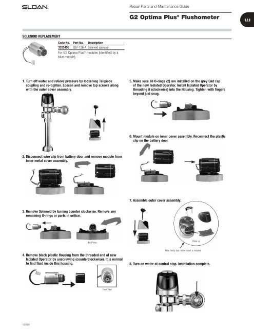
Repair Parts and Maintenance Guide G2 Optima Plus ® Flushometer 3.2.3 SOLENOID REPLACEMENT Code No. Part No. Description 3325453 EBV-136-A Solenoid operator For G2 Optima Plus ® modules (identified by a blue module). 1. Turn off water and relieve pressure by loosening Tailpiece coupling and re-tighten. Loosen and remove top screws along with the outer cover assembly. 5. Make sure all O-rings (2) are installed on the grey End cap of the new Isolated Operator. Install Isolated Operator by threading it (clockwise) into the Housing. Tighten with fingers beyond just snug. 6. Mount module on inner cover assembly. Reconnect the plastic clip on the battery door. 2. Disconnect wire clip from battery door and remove module from inner metal cover assembly. 7. Assemble outer cover assembly. 3. Remove Solenoid by turning counter clockwise. Remove any remaining O-rings or parts in orifice. Back View Close up 4. Remove black plastic Housing from the threaded end of new Isolated Operator by unscrewing (counterclockwise). It is normal to find fluid inside this housing. Note. Verify that rubber insert is installed 8. Turn on water at control stop. Installation complete. Front View 102008
- Page 1: Repair Parts and Maintenance Guide
- Page 5: Repair Parts and Maintenance Guide
Repair Parts and Maintenance Guide<br />
<strong>G2</strong> <strong>Optima</strong> Plus ® <strong>Flushometer</strong><br />
3.2.3<br />
SOLENOID REPLACEMENT<br />
Code No. Part No. Description<br />
3325453 EBV-136-A Solenoid operator<br />
For <strong>G2</strong> <strong>Optima</strong> Plus ® modules (identified by a<br />
blue module).<br />
1. Turn off water and relieve pressure by loosening Tailpiece<br />
coupling and re-tighten. Loosen and remove top screws along<br />
with the outer cover assembly.<br />
5. Make sure all O-rings (2) are installed on the grey End cap<br />
of the new Isolated Operator. Install Isolated Operator by<br />
threading it (clockwise) into the Housing. Tighten with fingers<br />
beyond just snug.<br />
6. Mount module on inner cover assembly. Reconnect the plastic<br />
clip on the battery door.<br />
2. Disconnect wire clip from battery door and remove module from<br />
inner metal cover assembly.<br />
7. Assemble outer cover assembly.<br />
3. Remove Solenoid by turning counter clockwise. Remove any<br />
remaining O-rings or parts in orifice.<br />
Back View<br />
Close up<br />
4. Remove black plastic Housing from the threaded end of new<br />
Isolated Operator by unscrewing (counterclockwise). It is normal<br />
to find fluid inside this housing.<br />
Note. Verify that rubber insert is installed<br />
8. Turn on water at control stop. Installation complete.<br />
Front View<br />
102008


