

G2 Optima Plus® Flushometer - Sloan Valve Company
G2 Optima Plus® Flushometer - Sloan Valve Company
G2 Optima Plus® Flushometer - Sloan Valve Company

Create successful ePaper yourself
Turn your PDF publications into a flip-book with our unique Google optimized e-Paper software.
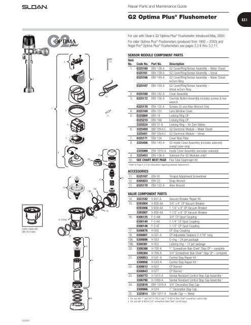
Repair Parts and Maintenance Guide<br />
<strong>G2</strong> <strong>Optima</strong> Plus ® <strong>Flushometer</strong><br />
3.2.1<br />
For use with <strong>Sloan</strong>’s <strong>G2</strong> <strong>Optima</strong> Plus ® <strong>Flushometer</strong> introduced May, 2003.<br />
For older <strong>Optima</strong> Plus ® <strong>Flushometer</strong>s (produced from 1992 – 2003) and<br />
Regal Pro ® <strong>Optima</strong> Plus ® <strong>Flushometer</strong>s see pages 3.2.6 thru 3.2.11.<br />
SENSOR MODULE COMPONENT PARTS<br />
1<br />
8<br />
3<br />
4<br />
5<br />
6<br />
7<br />
9<br />
24<br />
2<br />
23<br />
13<br />
12<br />
11<br />
Item<br />
No. Code No. Part No. Description<br />
1. 0325160 EBV-138-A <strong>G2</strong> Cover/Ring/Sensor Assembly – Water Closet<br />
0325161 EBV-139-A <strong>G2</strong> Cover/Ring/Sensor Assembly – Urinal<br />
0325166 EBV-149-A <strong>G2</strong> Cover/Ring/Sensor Assembly – Water Closet<br />
w/Zurn Ring<br />
0325167 EBV-150-A <strong>G2</strong> Cover/Ring/Sensor Assembly –<br />
Urinal w/Zurn Ring<br />
2. 0325168 EBV-142-A Cover Assembly<br />
3. 0325172 EBV-130-A Override Button Assembly includes screws & hex<br />
wrench<br />
0325170 EBV-132-A Screws (2) and Allen Wrench Only<br />
4. 0325169 EBV-131 Lens Window Cover<br />
5. 0325804 EBV-14 Locking Ring CP<br />
0325210 EBV-168 Locking Ring CP<br />
3325524 EBV-31-A Locking Ring – for Zurn <strong>Valve</strong>s<br />
6. 3325450 EBV-129-A-C <strong>G2</strong> Electronic Module – Water Closet<br />
3325451 EBV-129-A-U <strong>G2</strong> Electronic Module – Urinal<br />
7. 0325171 EBV-134 Cover Rest Plate<br />
8. 3325456 EBV-145-A <strong>G2</strong> Inside Cover Assembly (includes solenoid)<br />
(metal cover only)<br />
3325089 EBV-1010-A Inside Cover Assembly (excludes solenoid)<br />
9. 3325453 EBV-136-A Solenoid (For <strong>G2</strong> Modules only)*<br />
10. SEE CHART NEXT PAGE Flex Tube Diaphragm Kit<br />
22<br />
* Refer to Page 3.2.3 for instructions regarding solenoid replacement.<br />
ACCESSORIES<br />
10<br />
19A<br />
19B<br />
21<br />
20<br />
11. 0325107 EBV-91 Trimpot Adjustment Screwdriver<br />
12. 0305823 EBV-22 Strap Wrench<br />
13. 0325170 EBV-132-A Allen Wrench<br />
VALVE COMPONENT PARTS<br />
Earlier model with<br />
EBV-36-A body<br />
A-3 Body<br />
25<br />
17<br />
14<br />
15<br />
18<br />
14. 3323182 V-651-A Vacuum Breaker Repair Kit<br />
15. 0393004 V-600-AA 3/4’’ x 9’’ CP Vacuum Breaker<br />
0393006 V-600-AA 1-1/4’’ x 9’’ CP Vacuum Breaker<br />
3393007 V-600-AA 1-1/2’’ x 9’’ CP Vacuum Breaker<br />
16. 0306125 F-5-AW 3/4’’ CP Spud Coupling<br />
0306140 F-5-AU 1-1/4’’ CP Spud Coupling<br />
0306146 F-5-AT 1-1/2’’ CP Spud Coupling<br />
17. 0308676 H-550 CP Stop Coupling<br />
18. 0308801 H-551-A CP Adjustable Tailpiece 2-1/16’’ long<br />
19A. 5308696 H-553 O-ring – 24 per package<br />
19B. 5308381 H-552 Locking ring – 12 per package<br />
20. 3308386 H-700-A 1’’ Screwdriver Bak-Chek ® Stop CP – complete<br />
3308384 H-700-A 3/4’’ Screwdriver Bak-Chek ® Stop CP – complete<br />
21. 3308853 H-541-A Control Stop Repair Kit †<br />
3308856 H-543-A Control Stop Repair Kit ‡<br />
22. 0308612 H-622 CP Bonnet †<br />
0308843 H-577 CP Bonnet ‡<br />
23. 3308772 H-1010-A Vandal Resistant Control Stop Cap Assembly †<br />
3308790 H-1009-A Vandal Resistant Control Stop Cap Assembly ‡<br />
24. 3325816 EBV-1019-A 3/4’’ Decorative Stop Cap<br />
3308866 H-574 1’’ Decorative Stop Cap<br />
25. 3325814 EBV-1017-A Handle Cap — Metal<br />
16<br />
† For use with 1” and 3/4” H-700-A and 1” H-600-A Bak-Chek ® screwdriver control stop<br />
‡ For use with H-600-A 3/4’’ screwdriver Bak-Chek ® control stops<br />
012010
Repair Parts and Maintenance Guide<br />
3.2.2<br />
<strong>G2</strong> <strong>Optima</strong> Plus ® <strong>Flushometer</strong><br />
The <strong>Sloan</strong> <strong>Valve</strong> <strong>Company</strong> introduced its <strong>Optima</strong> Plus ® battery operated<br />
sensor <strong>Flushometer</strong> in 1992, revolutionizing the flushing of water closets<br />
and urinals. In both new construction and retrofit applications, the use of the<br />
<strong>Optima</strong> Plus has become the standard method for many facilities to improve<br />
restroom hygiene and ensure handicap accessibility compliance.<br />
In May, 2003 <strong>Sloan</strong> introduced the <strong>G2</strong> <strong>Optima</strong> Plus.<br />
The <strong>G2</strong> <strong>Optima</strong> Plus builds on the success of the original product and offers<br />
many technological advancements to further improve on performance and<br />
reliability expected of sensor operated plumbing. In addition to a new<br />
aesthetic design, the <strong>G2</strong> <strong>Optima</strong> Plus features a new state-of-the-art<br />
electronic and optical package and a unique solenoid operator that keeps the<br />
moving components of the solenoid completely isolated from the water<br />
supply. This ensures long life and low maintenance regardless of local<br />
water condition.<br />
The <strong>G2</strong> <strong>Optima</strong> Plus replaces the original <strong>Optima</strong> Plus product, which was<br />
phased out of production in mid-2003.<br />
The <strong>Sloan</strong> <strong>G2</strong> <strong>Optima</strong> Plus automatic battery powered <strong>Flushometer</strong> relies on<br />
an infrared sensor to detect a user and activate a flushing cycle. No physical<br />
contact with the <strong>Flushometer</strong> surface is necessary, assuring sanitary<br />
protection. <strong>G2</strong> <strong>Optima</strong> Plus <strong>Flushometer</strong>s are ADA compliant devices.<br />
The <strong>Flushometer</strong> is triggered by means of an active infrared sensor. The<br />
<strong>Optima</strong> Plus sensor emits a continuous invisible light beam. When a user<br />
enters the beam’s effective range, the beam is reflected into the <strong>Optima</strong><br />
Plus scanner window. The user is now detected. After the user moves out of<br />
the effective range of the sensor, a signal is sent to the <strong>Flushometer</strong><br />
solenoid and, after appropriate arming and/or flush delays, the flush cycle<br />
is initiated.<br />
LOCKING RING<br />
COVER<br />
BODY<br />
OVERRIDE BUTTON<br />
STOP COUPLING<br />
CONTROL STOP<br />
FLUSH CONNECTION<br />
(VACUUM BREAKER)<br />
TAILPIECE<br />
OUTLET COUPLING<br />
SUPPLY FLANGE<br />
SPUD COUPLING<br />
SPUD FLANGE<br />
FLEX TUBE DIAPHRAGM KIT<br />
Regulator<br />
Code No. Part No. Description Color *<br />
3325003 EBV-1023-A Urinal-0.5 gpf/1.9 Lpf †‡ GREEN<br />
3325000 EBV-1022-A Urinal-1.0 gpf/3.8 Lpf GREEN<br />
3325000 EBV-1022-A Urinal-1.5 gpf/5.7 Lpf † BLACK<br />
3325001 EBV-1020-A Urinal-3.5 gpf/13.2 Lpf † WHITE<br />
3325031 EBV-1024-A Closet-1.28 gpf/4.8 Lpf GREEN<br />
3325001 EBV-1020-A Closet-1.6 gpf/6.0 Lpf † GREEN<br />
3325014 EBV-1021-A Closet-2.4 gpf/9.0 Lpf BLUE<br />
3325001 EBV-1020-A Closet-3.5 gpf/13.2 Lpf WHITE<br />
3325001 EBV-1020-A Closet-4.5 gpf/17.0 Lpf § WHITE<br />
† EBV-1020-A and EBV-1022-A are supplied with multiple regulators.<br />
‡ A 0.5 gpf (1.9 Lpf) urinal kit can be converted to a 1.0 gpf (3.8 Lpf) by cutting and removing the<br />
smooth A-164 flow ring from the guide.<br />
§ For a 4.5 gpf (17 Lpf) water closet flush use EBV-1020-A with the white regulator, and cut and remove the<br />
A-164 flow ring from the guide.<br />
* Color of regulator to be used with flex tube diaphragm to obtain the listed flush volume.<br />
REGULATORS<br />
The flush volume of the flex tube diaphragm kit is controlled by the<br />
regulator. Regulators are identified by color. Some flex tube diaphragm kits<br />
are supplied with multiple regulators. The installer must make sure the<br />
proper regulator is used when installing the flex tube diaphragm kit.<br />
REGULATOR (SOLD 6 PER PACKAGE)<br />
Regulator<br />
Code No. Part No. Description Color<br />
5325122 EBV-95 Urinal-0.5 gpf/1.9 Lpf GREEN<br />
5325122 EBV-95 Urinal-1.0 gpf/3.8 Lpf GREEN<br />
5325129 EBV-102-2 Urinal-1.5 gpf/5.7 Lpf BLACK<br />
5325130 EBV-102-1 Urinal-3.5 gpf/13.2 Lpf WHITE<br />
5325122 EBV-95 Closet-1.28 gpf/4.8 Lpf GREEN<br />
5325122 EBV-95 Closet-1.6 gpf/6.0 Lpf GREEN<br />
5325130 EBV-102-1 Closet-3.5 gpf/13.2 Lpf WHITE<br />
5325128 EBV-101 Closet-2.4 gpf/9.0 Lpf BLUE<br />
EBV-1020-A and EBV-1022-A are supplied with multiple flush volume regulators.<br />
The installer must use the correct regulator when installing the kit.<br />
O-RING<br />
Code No. Part No. Description<br />
5325056 EBV-83 O-ring – 6 per package<br />
REGULATOR<br />
O-RING<br />
(Code No. 5325056)<br />
0-RING<br />
REGULATOR<br />
(MUST BE<br />
INSTALLED<br />
PAST 0-RING)<br />
FLEX TUBE<br />
DIAPHRAGM<br />
FLEX TUBE<br />
DIAPHRAGM<br />
082009
Repair Parts and Maintenance Guide<br />
<strong>G2</strong> <strong>Optima</strong> Plus ® <strong>Flushometer</strong><br />
3.2.3<br />
SOLENOID REPLACEMENT<br />
Code No. Part No. Description<br />
3325453 EBV-136-A Solenoid operator<br />
For <strong>G2</strong> <strong>Optima</strong> Plus ® modules (identified by a<br />
blue module).<br />
1. Turn off water and relieve pressure by loosening Tailpiece<br />
coupling and re-tighten. Loosen and remove top screws along<br />
with the outer cover assembly.<br />
5. Make sure all O-rings (2) are installed on the grey End cap<br />
of the new Isolated Operator. Install Isolated Operator by<br />
threading it (clockwise) into the Housing. Tighten with fingers<br />
beyond just snug.<br />
6. Mount module on inner cover assembly. Reconnect the plastic<br />
clip on the battery door.<br />
2. Disconnect wire clip from battery door and remove module from<br />
inner metal cover assembly.<br />
7. Assemble outer cover assembly.<br />
3. Remove Solenoid by turning counter clockwise. Remove any<br />
remaining O-rings or parts in orifice.<br />
Back View<br />
Close up<br />
4. Remove black plastic Housing from the threaded end of new<br />
Isolated Operator by unscrewing (counterclockwise). It is normal<br />
to find fluid inside this housing.<br />
Note. Verify that rubber insert is installed<br />
8. Turn on water at control stop. Installation complete.<br />
Front View<br />
102008
Repair Parts and Maintenance Guide<br />
3.2.4<br />
<strong>G2</strong> <strong>Optima</strong> Plus ® <strong>Flushometer</strong><br />
BATTERY REPLACEMENT<br />
When <strong>G2</strong> <strong>Optima</strong> Plus ® has approximately 4,000 flushes left, the same red<br />
light that appears at start-up will flash four (4) times quickly whenever an<br />
object is detected. When this occurs, we recommend changing the batteries<br />
as follows:<br />
When required, replace batteries with four (4) alkaline type AA batteries.<br />
Note: Water does not have to be turned off to replace batteries.<br />
Loosen the two (2) screws on top of unit. Remove the complete cover<br />
assembly. Lift the sensor module from its plate. Unplug the electrical<br />
connector from battery compartment cover. Loosen the retaining screw on<br />
battery compartment cover and remove battery compartment cover. Install<br />
four (4) alkaline type AA batteries exactly as illustrated at right.<br />
Install battery compartment cover and secure with retaining screw. Make<br />
certain that battery compartment cover is fully compressed against gasket<br />
to provide a seal; Do not overtighten. Plug the electrical connector into the<br />
battery compartment cover. Reinstall the sensor module onto the plate.<br />
Reinstall the complete cover assembly onto the plate. Tighten the two<br />
(2) screws on top of the unit.<br />
7/64” ALLEN WRENCH<br />
COVER ASSEMBLY<br />
SENSOR MODULE<br />
PLATE<br />
SENSOR MODULE (BACKSIDE SHOWN)<br />
RETAINING SCREW<br />
ELECTRICAL CONNECTOR<br />
RECEPTACLE<br />
BATTERY COMPARTMENT COVER<br />
RANGE ADJUSTMENT (ADJUST ONLY IF NECESSARY)<br />
The <strong>G2</strong> <strong>Optima</strong> Plus has a factory set sensing range:<br />
Water closet models – 22" to 42" (559 mm to 1067 mm)<br />
Urinal models – 15" to 30" (381 mm to 762 mm)<br />
The Factory setting should be satisfactory for most installations.<br />
If the range is too short (i.e., not picking up users) or too long (i.e., picking<br />
up opposite wall or stall door) the range can be adjusted.<br />
Note: Water does not have to be turned off to adjust range.<br />
Loosen the two screws on top of the unit. Remove the override button.<br />
Remove the rubber plug from top of electronic sensor module to uncover<br />
the potentiometer.<br />
COUNTERCLOCKWISE<br />
Decreases<br />
Range<br />
CLOCKWISE<br />
Increases<br />
Range<br />
RANGE ADJUSTMENT PROCEDURE<br />
For the first ten (10) minutes of operation, a visible red light flashes in the<br />
sensing window of the <strong>G2</strong> <strong>Optima</strong> Plus <strong>Flushometer</strong> when a user is<br />
detected. This visible red light feature can be reactivated after ten (10)<br />
minutes by opening and closing the battery compartment door or holding<br />
the override button for (1) minute.<br />
Check the range by stepping toward the unit until the red light flashes,<br />
indicating the sensor’s detection of a user. Adjust the range potentiometer<br />
screw located on top of the sensor module a few degrees CLOCKWISE to<br />
increase the range or a few degrees COUNTERCLOCKWISE to decrease the<br />
range. Repeat this adjustment until the desired range is achieved.<br />
Always determine the sensing range with metal cover and lens<br />
window on top of the unit.<br />
Important: Adjust in small increments only! Range potentiometer<br />
adjustment screw rotates only 3/4 of a turn; DO NOT over-rotate.<br />
When range adjustment is satisfactory, replace the rubber plug. Reinstall<br />
override button and tighten the two screws on top of the unit.<br />
062006
Repair Parts and Maintenance Guide<br />
<strong>G2</strong> <strong>Optima</strong> Plus ® <strong>Flushometer</strong><br />
3.2.5<br />
TROUBLESHOOTING AND MAINTAINING THE SLOAN <strong>G2</strong> OPTIMA PLUS ® FLUSHOMETER<br />
IMPORTANT: This product contains mechanical and/or electrical<br />
components that are subject to normal wear. These components should be<br />
checked on a regular basis and replaced as needed to maintain the valve’s<br />
performance.<br />
Never open Control Stop to where the flow from the valve exceeds the flow<br />
capability of the fixture. In the event of a valve failure, the fixture must be<br />
able to accommodate a continuous flow from the valve.<br />
ATTENTION INSTALLERS: With the exception of the control stop inlet,<br />
DO NOT USE pipe sealant or plumbing grease on any valve component or<br />
coupling! To protect the chrome or special finish of <strong>Sloan</strong> <strong>Flushometer</strong>s,<br />
DO NOT USE toothed tools to install or service these valves. Use our A-50<br />
Super-Wrench or other smooth-jawed wrench to secure couplings.<br />
Regulations for low consumption fixtures (1.6 gpf/6.0 Lpf closets and<br />
1.0 gpf/3.8 Lpf urinals) prohibit use of higher flush volumes.<br />
1. Sensor flashes continuously only when user steps within range.<br />
A. Unit in start-up mode; no problem. This feature is active for the first<br />
ten (10) minutes of operation.<br />
2. <strong>Valve</strong> does not flush; sensor not picking up user.<br />
A. Range too short; increase the range.<br />
3. <strong>Valve</strong> does not flush; sensor picking up opposite wall or surface,<br />
or only flushes when someone walks by. Red light flashes<br />
continuously for first 10 minutes even with no one in front of<br />
the sensor.<br />
A. Range too long; shorten range.<br />
4. <strong>Valve</strong> does not flush even after adjustment.<br />
A. Range adjustment potentiometer set at full “max” or full “min” setting.<br />
Readjust potentiometer away from full “max” or “min” setting.<br />
B. Batteries completely used up; replace batteries.<br />
C. Problem with electronic sensor module; replace electronic sensor<br />
module.<br />
5. Unit flashes 4 quick times when user steps within range.<br />
A. Batteries low; replace batteries.<br />
6. <strong>Valve</strong> does not shut off.<br />
A. By-pass orifice in diaphragm is clogged with dirt or debris, or by-pass<br />
is clogged by an invisible gelatinous film due to “over-treated” water.<br />
Remove flex tube diaphragm and wash under running water.<br />
Note: Size of orifice in the by-pass is of utmost importance for the<br />
proper metering of water by the valve. DO NOT ENLARGE OR<br />
DAMAGE THIS ORIFICE. Replace flex tube diaphragm if cleaning<br />
does not correct the problem.<br />
B. Dirt or debris fouling stem or flex tube diaphragm. Remove flex tube<br />
diaphragm and wash under running water.<br />
C. O-ring on stem of flex tube diaphragm is damaged or worn. Replace<br />
O-ring if necessary.<br />
D. Problem with solenoid. If cleaning does not correct problem, replace<br />
with new solenoid operator.<br />
7. Not enough water to fixture.<br />
A. Wrong flush volume regulator installed in flex tube diaphragm kit.<br />
Install the correct regulator.<br />
B. Wrong <strong>Optima</strong> Plus ® model installed; i.e., 1.0 gpf urinal installed<br />
on 3.5 gpf closet fixture. Replace with proper <strong>Optima</strong> Plus model.<br />
C. Enlarged by-pass in diaphragm. Replace flex tube diaphragm.<br />
D. Control stop not adjusted properly. Readjust control stop.<br />
E. Inadequate volume or pressure at supply. Increase water pressure<br />
or supply (flow) to valve. Consult factory for assistance.<br />
8. Too much water to fixture.<br />
A. Wrong flush volume regulator installed in flex tube diaphragm kit.<br />
Install the correct regulator.<br />
B. Control stop not adjusted properly. Readjust control stop.<br />
C. Wrong <strong>Optima</strong> Plus model installed; i.e., 3 gpf model installed on 1.0<br />
or 1.5 gpf urinal fixture.<br />
D. Dirt in diaphragm by-pass. Clean under running water or replace flex<br />
tube diaphragm.<br />
Note: The EBV-46-A beam deflector is no longer required or available<br />
for the <strong>G2</strong> <strong>Optima</strong> Plus.<br />
CARE AND CLEANING INSTRUCTIONS<br />
DO NOT use abrasive or chemical cleaners to clean the <strong>G2</strong> <strong>Optima</strong> Plus, they<br />
may dull the luster and attack the plastic cover and the chrome finish of the<br />
<strong>Flushometer</strong>. Use ONLY mild soap and water, then wipe dry with clean cloth<br />
or towel. While cleaning the bathroom tile, the <strong>Optima</strong> Plus should be<br />
protected from any splattering of cleaner. Acids and cleaning fluids can<br />
discolor or remove chrome plating.<br />
062007


