

G2 Optima Plus® Flushometer - Sloan Valve Company
G2 Optima Plus® Flushometer - Sloan Valve Company
G2 Optima Plus® Flushometer - Sloan Valve Company

You also want an ePaper? Increase the reach of your titles
YUMPU automatically turns print PDFs into web optimized ePapers that Google loves.
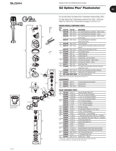
Repair Parts and Maintenance Guide<br />
<strong>G2</strong> <strong>Optima</strong> Plus ® <strong>Flushometer</strong><br />
3.2.1<br />
For use with <strong>Sloan</strong>’s <strong>G2</strong> <strong>Optima</strong> Plus ® <strong>Flushometer</strong> introduced May, 2003.<br />
For older <strong>Optima</strong> Plus ® <strong>Flushometer</strong>s (produced from 1992 – 2003) and<br />
Regal Pro ® <strong>Optima</strong> Plus ® <strong>Flushometer</strong>s see pages 3.2.6 thru 3.2.11.<br />
SENSOR MODULE COMPONENT PARTS<br />
1<br />
8<br />
3<br />
4<br />
5<br />
6<br />
7<br />
9<br />
24<br />
2<br />
23<br />
13<br />
12<br />
11<br />
Item<br />
No. Code No. Part No. Description<br />
1. 0325160 EBV-138-A <strong>G2</strong> Cover/Ring/Sensor Assembly – Water Closet<br />
0325161 EBV-139-A <strong>G2</strong> Cover/Ring/Sensor Assembly – Urinal<br />
0325166 EBV-149-A <strong>G2</strong> Cover/Ring/Sensor Assembly – Water Closet<br />
w/Zurn Ring<br />
0325167 EBV-150-A <strong>G2</strong> Cover/Ring/Sensor Assembly –<br />
Urinal w/Zurn Ring<br />
2. 0325168 EBV-142-A Cover Assembly<br />
3. 0325172 EBV-130-A Override Button Assembly includes screws & hex<br />
wrench<br />
0325170 EBV-132-A Screws (2) and Allen Wrench Only<br />
4. 0325169 EBV-131 Lens Window Cover<br />
5. 0325804 EBV-14 Locking Ring CP<br />
0325210 EBV-168 Locking Ring CP<br />
3325524 EBV-31-A Locking Ring – for Zurn <strong>Valve</strong>s<br />
6. 3325450 EBV-129-A-C <strong>G2</strong> Electronic Module – Water Closet<br />
3325451 EBV-129-A-U <strong>G2</strong> Electronic Module – Urinal<br />
7. 0325171 EBV-134 Cover Rest Plate<br />
8. 3325456 EBV-145-A <strong>G2</strong> Inside Cover Assembly (includes solenoid)<br />
(metal cover only)<br />
3325089 EBV-1010-A Inside Cover Assembly (excludes solenoid)<br />
9. 3325453 EBV-136-A Solenoid (For <strong>G2</strong> Modules only)*<br />
10. SEE CHART NEXT PAGE Flex Tube Diaphragm Kit<br />
22<br />
* Refer to Page 3.2.3 for instructions regarding solenoid replacement.<br />
ACCESSORIES<br />
10<br />
19A<br />
19B<br />
21<br />
20<br />
11. 0325107 EBV-91 Trimpot Adjustment Screwdriver<br />
12. 0305823 EBV-22 Strap Wrench<br />
13. 0325170 EBV-132-A Allen Wrench<br />
VALVE COMPONENT PARTS<br />
Earlier model with<br />
EBV-36-A body<br />
A-3 Body<br />
25<br />
17<br />
14<br />
15<br />
18<br />
14. 3323182 V-651-A Vacuum Breaker Repair Kit<br />
15. 0393004 V-600-AA 3/4’’ x 9’’ CP Vacuum Breaker<br />
0393006 V-600-AA 1-1/4’’ x 9’’ CP Vacuum Breaker<br />
3393007 V-600-AA 1-1/2’’ x 9’’ CP Vacuum Breaker<br />
16. 0306125 F-5-AW 3/4’’ CP Spud Coupling<br />
0306140 F-5-AU 1-1/4’’ CP Spud Coupling<br />
0306146 F-5-AT 1-1/2’’ CP Spud Coupling<br />
17. 0308676 H-550 CP Stop Coupling<br />
18. 0308801 H-551-A CP Adjustable Tailpiece 2-1/16’’ long<br />
19A. 5308696 H-553 O-ring – 24 per package<br />
19B. 5308381 H-552 Locking ring – 12 per package<br />
20. 3308386 H-700-A 1’’ Screwdriver Bak-Chek ® Stop CP – complete<br />
3308384 H-700-A 3/4’’ Screwdriver Bak-Chek ® Stop CP – complete<br />
21. 3308853 H-541-A Control Stop Repair Kit †<br />
3308856 H-543-A Control Stop Repair Kit ‡<br />
22. 0308612 H-622 CP Bonnet †<br />
0308843 H-577 CP Bonnet ‡<br />
23. 3308772 H-1010-A Vandal Resistant Control Stop Cap Assembly †<br />
3308790 H-1009-A Vandal Resistant Control Stop Cap Assembly ‡<br />
24. 3325816 EBV-1019-A 3/4’’ Decorative Stop Cap<br />
3308866 H-574 1’’ Decorative Stop Cap<br />
25. 3325814 EBV-1017-A Handle Cap — Metal<br />
16<br />
† For use with 1” and 3/4” H-700-A and 1” H-600-A Bak-Chek ® screwdriver control stop<br />
‡ For use with H-600-A 3/4’’ screwdriver Bak-Chek ® control stops<br />
012010
Repair Parts and Maintenance Guide<br />
3.2.2<br />
<strong>G2</strong> <strong>Optima</strong> Plus ® <strong>Flushometer</strong><br />
The <strong>Sloan</strong> <strong>Valve</strong> <strong>Company</strong> introduced its <strong>Optima</strong> Plus ® battery operated<br />
sensor <strong>Flushometer</strong> in 1992, revolutionizing the flushing of water closets<br />
and urinals. In both new construction and retrofit applications, the use of the<br />
<strong>Optima</strong> Plus has become the standard method for many facilities to improve<br />
restroom hygiene and ensure handicap accessibility compliance.<br />
In May, 2003 <strong>Sloan</strong> introduced the <strong>G2</strong> <strong>Optima</strong> Plus.<br />
The <strong>G2</strong> <strong>Optima</strong> Plus builds on the success of the original product and offers<br />
many technological advancements to further improve on performance and<br />
reliability expected of sensor operated plumbing. In addition to a new<br />
aesthetic design, the <strong>G2</strong> <strong>Optima</strong> Plus features a new state-of-the-art<br />
electronic and optical package and a unique solenoid operator that keeps the<br />
moving components of the solenoid completely isolated from the water<br />
supply. This ensures long life and low maintenance regardless of local<br />
water condition.<br />
The <strong>G2</strong> <strong>Optima</strong> Plus replaces the original <strong>Optima</strong> Plus product, which was<br />
phased out of production in mid-2003.<br />
The <strong>Sloan</strong> <strong>G2</strong> <strong>Optima</strong> Plus automatic battery powered <strong>Flushometer</strong> relies on<br />
an infrared sensor to detect a user and activate a flushing cycle. No physical<br />
contact with the <strong>Flushometer</strong> surface is necessary, assuring sanitary<br />
protection. <strong>G2</strong> <strong>Optima</strong> Plus <strong>Flushometer</strong>s are ADA compliant devices.<br />
The <strong>Flushometer</strong> is triggered by means of an active infrared sensor. The<br />
<strong>Optima</strong> Plus sensor emits a continuous invisible light beam. When a user<br />
enters the beam’s effective range, the beam is reflected into the <strong>Optima</strong><br />
Plus scanner window. The user is now detected. After the user moves out of<br />
the effective range of the sensor, a signal is sent to the <strong>Flushometer</strong><br />
solenoid and, after appropriate arming and/or flush delays, the flush cycle<br />
is initiated.<br />
LOCKING RING<br />
COVER<br />
BODY<br />
OVERRIDE BUTTON<br />
STOP COUPLING<br />
CONTROL STOP<br />
FLUSH CONNECTION<br />
(VACUUM BREAKER)<br />
TAILPIECE<br />
OUTLET COUPLING<br />
SUPPLY FLANGE<br />
SPUD COUPLING<br />
SPUD FLANGE<br />
FLEX TUBE DIAPHRAGM KIT<br />
Regulator<br />
Code No. Part No. Description Color *<br />
3325003 EBV-1023-A Urinal-0.5 gpf/1.9 Lpf †‡ GREEN<br />
3325000 EBV-1022-A Urinal-1.0 gpf/3.8 Lpf GREEN<br />
3325000 EBV-1022-A Urinal-1.5 gpf/5.7 Lpf † BLACK<br />
3325001 EBV-1020-A Urinal-3.5 gpf/13.2 Lpf † WHITE<br />
3325031 EBV-1024-A Closet-1.28 gpf/4.8 Lpf GREEN<br />
3325001 EBV-1020-A Closet-1.6 gpf/6.0 Lpf † GREEN<br />
3325014 EBV-1021-A Closet-2.4 gpf/9.0 Lpf BLUE<br />
3325001 EBV-1020-A Closet-3.5 gpf/13.2 Lpf WHITE<br />
3325001 EBV-1020-A Closet-4.5 gpf/17.0 Lpf § WHITE<br />
† EBV-1020-A and EBV-1022-A are supplied with multiple regulators.<br />
‡ A 0.5 gpf (1.9 Lpf) urinal kit can be converted to a 1.0 gpf (3.8 Lpf) by cutting and removing the<br />
smooth A-164 flow ring from the guide.<br />
§ For a 4.5 gpf (17 Lpf) water closet flush use EBV-1020-A with the white regulator, and cut and remove the<br />
A-164 flow ring from the guide.<br />
* Color of regulator to be used with flex tube diaphragm to obtain the listed flush volume.<br />
REGULATORS<br />
The flush volume of the flex tube diaphragm kit is controlled by the<br />
regulator. Regulators are identified by color. Some flex tube diaphragm kits<br />
are supplied with multiple regulators. The installer must make sure the<br />
proper regulator is used when installing the flex tube diaphragm kit.<br />
REGULATOR (SOLD 6 PER PACKAGE)<br />
Regulator<br />
Code No. Part No. Description Color<br />
5325122 EBV-95 Urinal-0.5 gpf/1.9 Lpf GREEN<br />
5325122 EBV-95 Urinal-1.0 gpf/3.8 Lpf GREEN<br />
5325129 EBV-102-2 Urinal-1.5 gpf/5.7 Lpf BLACK<br />
5325130 EBV-102-1 Urinal-3.5 gpf/13.2 Lpf WHITE<br />
5325122 EBV-95 Closet-1.28 gpf/4.8 Lpf GREEN<br />
5325122 EBV-95 Closet-1.6 gpf/6.0 Lpf GREEN<br />
5325130 EBV-102-1 Closet-3.5 gpf/13.2 Lpf WHITE<br />
5325128 EBV-101 Closet-2.4 gpf/9.0 Lpf BLUE<br />
EBV-1020-A and EBV-1022-A are supplied with multiple flush volume regulators.<br />
The installer must use the correct regulator when installing the kit.<br />
O-RING<br />
Code No. Part No. Description<br />
5325056 EBV-83 O-ring – 6 per package<br />
REGULATOR<br />
O-RING<br />
(Code No. 5325056)<br />
0-RING<br />
REGULATOR<br />
(MUST BE<br />
INSTALLED<br />
PAST 0-RING)<br />
FLEX TUBE<br />
DIAPHRAGM<br />
FLEX TUBE<br />
DIAPHRAGM<br />
082009
Repair Parts and Maintenance Guide<br />
<strong>G2</strong> <strong>Optima</strong> Plus ® <strong>Flushometer</strong><br />
3.2.3<br />
SOLENOID REPLACEMENT<br />
Code No. Part No. Description<br />
3325453 EBV-136-A Solenoid operator<br />
For <strong>G2</strong> <strong>Optima</strong> Plus ® modules (identified by a<br />
blue module).<br />
1. Turn off water and relieve pressure by loosening Tailpiece<br />
coupling and re-tighten. Loosen and remove top screws along<br />
with the outer cover assembly.<br />
5. Make sure all O-rings (2) are installed on the grey End cap<br />
of the new Isolated Operator. Install Isolated Operator by<br />
threading it (clockwise) into the Housing. Tighten with fingers<br />
beyond just snug.<br />
6. Mount module on inner cover assembly. Reconnect the plastic<br />
clip on the battery door.<br />
2. Disconnect wire clip from battery door and remove module from<br />
inner metal cover assembly.<br />
7. Assemble outer cover assembly.<br />
3. Remove Solenoid by turning counter clockwise. Remove any<br />
remaining O-rings or parts in orifice.<br />
Back View<br />
Close up<br />
4. Remove black plastic Housing from the threaded end of new<br />
Isolated Operator by unscrewing (counterclockwise). It is normal<br />
to find fluid inside this housing.<br />
Note. Verify that rubber insert is installed<br />
8. Turn on water at control stop. Installation complete.<br />
Front View<br />
102008
Repair Parts and Maintenance Guide<br />
3.2.4<br />
<strong>G2</strong> <strong>Optima</strong> Plus ® <strong>Flushometer</strong><br />
BATTERY REPLACEMENT<br />
When <strong>G2</strong> <strong>Optima</strong> Plus ® has approximately 4,000 flushes left, the same red<br />
light that appears at start-up will flash four (4) times quickly whenever an<br />
object is detected. When this occurs, we recommend changing the batteries<br />
as follows:<br />
When required, replace batteries with four (4) alkaline type AA batteries.<br />
Note: Water does not have to be turned off to replace batteries.<br />
Loosen the two (2) screws on top of unit. Remove the complete cover<br />
assembly. Lift the sensor module from its plate. Unplug the electrical<br />
connector from battery compartment cover. Loosen the retaining screw on<br />
battery compartment cover and remove battery compartment cover. Install<br />
four (4) alkaline type AA batteries exactly as illustrated at right.<br />
Install battery compartment cover and secure with retaining screw. Make<br />
certain that battery compartment cover is fully compressed against gasket<br />
to provide a seal; Do not overtighten. Plug the electrical connector into the<br />
battery compartment cover. Reinstall the sensor module onto the plate.<br />
Reinstall the complete cover assembly onto the plate. Tighten the two<br />
(2) screws on top of the unit.<br />
7/64” ALLEN WRENCH<br />
COVER ASSEMBLY<br />
SENSOR MODULE<br />
PLATE<br />
SENSOR MODULE (BACKSIDE SHOWN)<br />
RETAINING SCREW<br />
ELECTRICAL CONNECTOR<br />
RECEPTACLE<br />
BATTERY COMPARTMENT COVER<br />
RANGE ADJUSTMENT (ADJUST ONLY IF NECESSARY)<br />
The <strong>G2</strong> <strong>Optima</strong> Plus has a factory set sensing range:<br />
Water closet models – 22" to 42" (559 mm to 1067 mm)<br />
Urinal models – 15" to 30" (381 mm to 762 mm)<br />
The Factory setting should be satisfactory for most installations.<br />
If the range is too short (i.e., not picking up users) or too long (i.e., picking<br />
up opposite wall or stall door) the range can be adjusted.<br />
Note: Water does not have to be turned off to adjust range.<br />
Loosen the two screws on top of the unit. Remove the override button.<br />
Remove the rubber plug from top of electronic sensor module to uncover<br />
the potentiometer.<br />
COUNTERCLOCKWISE<br />
Decreases<br />
Range<br />
CLOCKWISE<br />
Increases<br />
Range<br />
RANGE ADJUSTMENT PROCEDURE<br />
For the first ten (10) minutes of operation, a visible red light flashes in the<br />
sensing window of the <strong>G2</strong> <strong>Optima</strong> Plus <strong>Flushometer</strong> when a user is<br />
detected. This visible red light feature can be reactivated after ten (10)<br />
minutes by opening and closing the battery compartment door or holding<br />
the override button for (1) minute.<br />
Check the range by stepping toward the unit until the red light flashes,<br />
indicating the sensor’s detection of a user. Adjust the range potentiometer<br />
screw located on top of the sensor module a few degrees CLOCKWISE to<br />
increase the range or a few degrees COUNTERCLOCKWISE to decrease the<br />
range. Repeat this adjustment until the desired range is achieved.<br />
Always determine the sensing range with metal cover and lens<br />
window on top of the unit.<br />
Important: Adjust in small increments only! Range potentiometer<br />
adjustment screw rotates only 3/4 of a turn; DO NOT over-rotate.<br />
When range adjustment is satisfactory, replace the rubber plug. Reinstall<br />
override button and tighten the two screws on top of the unit.<br />
062006
Repair Parts and Maintenance Guide<br />
<strong>G2</strong> <strong>Optima</strong> Plus ® <strong>Flushometer</strong><br />
3.2.5<br />
TROUBLESHOOTING AND MAINTAINING THE SLOAN <strong>G2</strong> OPTIMA PLUS ® FLUSHOMETER<br />
IMPORTANT: This product contains mechanical and/or electrical<br />
components that are subject to normal wear. These components should be<br />
checked on a regular basis and replaced as needed to maintain the valve’s<br />
performance.<br />
Never open Control Stop to where the flow from the valve exceeds the flow<br />
capability of the fixture. In the event of a valve failure, the fixture must be<br />
able to accommodate a continuous flow from the valve.<br />
ATTENTION INSTALLERS: With the exception of the control stop inlet,<br />
DO NOT USE pipe sealant or plumbing grease on any valve component or<br />
coupling! To protect the chrome or special finish of <strong>Sloan</strong> <strong>Flushometer</strong>s,<br />
DO NOT USE toothed tools to install or service these valves. Use our A-50<br />
Super-Wrench or other smooth-jawed wrench to secure couplings.<br />
Regulations for low consumption fixtures (1.6 gpf/6.0 Lpf closets and<br />
1.0 gpf/3.8 Lpf urinals) prohibit use of higher flush volumes.<br />
1. Sensor flashes continuously only when user steps within range.<br />
A. Unit in start-up mode; no problem. This feature is active for the first<br />
ten (10) minutes of operation.<br />
2. <strong>Valve</strong> does not flush; sensor not picking up user.<br />
A. Range too short; increase the range.<br />
3. <strong>Valve</strong> does not flush; sensor picking up opposite wall or surface,<br />
or only flushes when someone walks by. Red light flashes<br />
continuously for first 10 minutes even with no one in front of<br />
the sensor.<br />
A. Range too long; shorten range.<br />
4. <strong>Valve</strong> does not flush even after adjustment.<br />
A. Range adjustment potentiometer set at full “max” or full “min” setting.<br />
Readjust potentiometer away from full “max” or “min” setting.<br />
B. Batteries completely used up; replace batteries.<br />
C. Problem with electronic sensor module; replace electronic sensor<br />
module.<br />
5. Unit flashes 4 quick times when user steps within range.<br />
A. Batteries low; replace batteries.<br />
6. <strong>Valve</strong> does not shut off.<br />
A. By-pass orifice in diaphragm is clogged with dirt or debris, or by-pass<br />
is clogged by an invisible gelatinous film due to “over-treated” water.<br />
Remove flex tube diaphragm and wash under running water.<br />
Note: Size of orifice in the by-pass is of utmost importance for the<br />
proper metering of water by the valve. DO NOT ENLARGE OR<br />
DAMAGE THIS ORIFICE. Replace flex tube diaphragm if cleaning<br />
does not correct the problem.<br />
B. Dirt or debris fouling stem or flex tube diaphragm. Remove flex tube<br />
diaphragm and wash under running water.<br />
C. O-ring on stem of flex tube diaphragm is damaged or worn. Replace<br />
O-ring if necessary.<br />
D. Problem with solenoid. If cleaning does not correct problem, replace<br />
with new solenoid operator.<br />
7. Not enough water to fixture.<br />
A. Wrong flush volume regulator installed in flex tube diaphragm kit.<br />
Install the correct regulator.<br />
B. Wrong <strong>Optima</strong> Plus ® model installed; i.e., 1.0 gpf urinal installed<br />
on 3.5 gpf closet fixture. Replace with proper <strong>Optima</strong> Plus model.<br />
C. Enlarged by-pass in diaphragm. Replace flex tube diaphragm.<br />
D. Control stop not adjusted properly. Readjust control stop.<br />
E. Inadequate volume or pressure at supply. Increase water pressure<br />
or supply (flow) to valve. Consult factory for assistance.<br />
8. Too much water to fixture.<br />
A. Wrong flush volume regulator installed in flex tube diaphragm kit.<br />
Install the correct regulator.<br />
B. Control stop not adjusted properly. Readjust control stop.<br />
C. Wrong <strong>Optima</strong> Plus model installed; i.e., 3 gpf model installed on 1.0<br />
or 1.5 gpf urinal fixture.<br />
D. Dirt in diaphragm by-pass. Clean under running water or replace flex<br />
tube diaphragm.<br />
Note: The EBV-46-A beam deflector is no longer required or available<br />
for the <strong>G2</strong> <strong>Optima</strong> Plus.<br />
CARE AND CLEANING INSTRUCTIONS<br />
DO NOT use abrasive or chemical cleaners to clean the <strong>G2</strong> <strong>Optima</strong> Plus, they<br />
may dull the luster and attack the plastic cover and the chrome finish of the<br />
<strong>Flushometer</strong>. Use ONLY mild soap and water, then wipe dry with clean cloth<br />
or towel. While cleaning the bathroom tile, the <strong>Optima</strong> Plus should be<br />
protected from any splattering of cleaner. Acids and cleaning fluids can<br />
discolor or remove chrome plating.<br />
062007


