

Royal® ES-S TMO | Installation Instructions - Sloan Valve Company
Royal® ES-S TMO | Installation Instructions - Sloan Valve Company
Royal® ES-S TMO | Installation Instructions - Sloan Valve Company

Create successful ePaper yourself
Turn your PDF publications into a flip-book with our unique Google optimized e-Paper software.
Code No. 0816431<br />
Rev. 5 (05/13)<br />
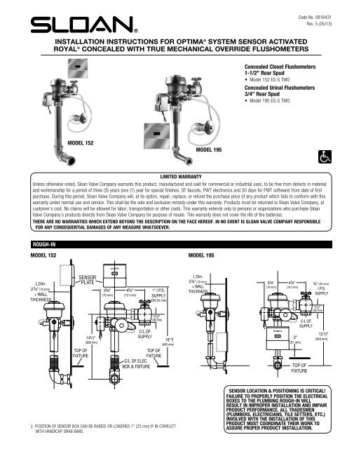
INSTALLATION INSTRUCTIONS FOR OPTIMA ® SYSTEM SENSOR ACTIVATED<br />
ROYAL ® CONCEALED WITH TRUE MECHANICAL OVERRIDE FLUSHOMETERS<br />
Concealed Closet Flushometers<br />
1-1/2” Rear Spud<br />
• Model 152 <strong>ES</strong>-S <strong>TMO</strong><br />
Concealed Urinal Flushometers<br />
3/4” Rear Spud<br />
• Model 195 <strong>ES</strong>-S <strong>TMO</strong><br />
MODEL 152<br />
MODEL 195<br />
LIMITED WARRANTY<br />
Unless otherwise noted, <strong>Sloan</strong> <strong>Valve</strong> <strong>Company</strong> warrants this product, manufactured and sold for commercial or industrial uses, to be free from defects in material<br />
and workmanship for a period of three (3) years (one (1) year for special finishes, SF faucets, PWT electronics and 30 days for PWT software) from date of first<br />
purchase. During this period, <strong>Sloan</strong> <strong>Valve</strong> <strong>Company</strong> will, at its option, repair, replace, or refund the purchase price of any product which fails to conform with this<br />
warranty under normal use and service. This shall be the sole and exclusive remedy under this warranty. Products must be returned to <strong>Sloan</strong> <strong>Valve</strong> <strong>Company</strong>, at<br />
customer’s cost. No claims will be allowed for labor, transportation or other costs. This warranty extends only to persons or organizations who purchase <strong>Sloan</strong><br />
<strong>Valve</strong> <strong>Company</strong>’s products directly from <strong>Sloan</strong> <strong>Valve</strong> <strong>Company</strong> for purpose of resale. This warranty does not cover the life of the batteries.<br />
THERE ARE NO WARRANTI<strong>ES</strong> WHICH EXTEND BEYOND THE D<strong>ES</strong>CRIPTION ON THE FACE HEREOF. IN NO EVENT IS SLOAN VALVE COMPANY R<strong>ES</strong>PONSIBLE<br />
FOR ANY CONSEQUENTIAL DAMAG<strong>ES</strong> OF ANY MEASURE WHATSOEVER.<br />
ROUGH-IN<br />
MODEL 152 MODEL 195<br />
‡ POSITION OF SENSOR BOX CAN BE RAISED OR LOWERED 1” (25 mm) IF IN CONFLICT<br />
WITH HANDICAP GRAB BARS.<br />
SENSOR LOCATION & POSITIONING IS CRITICAL!<br />
Failure to properly position the electrical<br />
boxes to the plumbing rough-in will<br />
result in improper installation and impair<br />
product performance. All tradesmen<br />
(plumbers, electricians, tile setters, etc.)<br />
involved with the installation of this<br />
product must coordinate their work to<br />
assure proper product installation.
PRIOR TO INSTALLATION<br />
Check the “L” dimension show on the Flushometer package is correct for your<br />
application. Determine the “L” dimension for your application by using the<br />
following formula:<br />
“L” dimension = Wall Thickness (to nearest the whole inch) + 2-3/4” (69 mm)<br />
Prior to installation, install the items listed below:<br />
• Electrical wiring to the transformer box (120 VAC, 2 amp service required for<br />
each EL-154, 24 VAC, 50 VA transformer used)<br />
• Bore a 1-1/2” (38 mm) opening in wall for the hydraulic push button<br />
actuator<br />
• Bore a 2” (51 mm) opening in wall for piping (if required)<br />
• Closet/Urinal fixture<br />
• Water supply line<br />
• Drain line<br />
IMPORTANT:<br />
• ALL PLUMBINGING AND ELECTRICAL WIRING SHOULD BE INSTALLED<br />
IN ACCORDANCE WITH APPLICABLE COD<strong>ES</strong> AND REGULATIONS.<br />
• WATER SUPPLY LIN<strong>ES</strong> MUST BE SIZED TO PROVIDE AN ADEQUATE<br />
VOLUME OF WATER FOR EACH FIXTURE.<br />
• A 24 VAC STEP-DOWN TRANSFORMER MUST BE USED.<br />
• WHEN INSTALLING A FLUSHOMETER, IT IS IMPORTANT THAT THE<br />
FLUSH MODEL MATCH<strong>ES</strong> THE REQUIREMENTS OF THE PLUMBING<br />
FIXTURE.<br />
• FLUSH ALL WATER LIN<strong>ES</strong> PRIOR TO MAKING CONNECTIONS.<br />
<strong>Sloan</strong> flushometers are designed to operate with 15 to 100 psi (104 to 689<br />
kPa) of water pressure. THE MINIMUM PR<strong>ES</strong>SURE REQUIRED TO THE<br />
VALVE IS DETERMINED BY THE TYPE OF FIXTURE SELECTED. Consult<br />
fixture manufacturer for minimum pressure requirements.<br />
Most Low Consumption water closets (1.6 gallon/6.0 liter) require a minimum<br />
flowing pressure of 25 psi (172 kPa).<br />
TRANSFORMER INSTALLATION<br />
Install transformer (EL-154) on a 2-Gang electrical Box, 4” x 4” x 2-1/2” (102<br />
mm x 102 mm x 64 mm) in a convenient location; refer to the illustration at<br />
right (Figure 1).<br />
Note: One <strong>Sloan</strong> EL-154 transformer can operate up to ten OPTIMA equipped<br />
flushometers. Run 18-gauge wire from transformer to flushometer(s). Wire<br />
supplied by others. DO NOT supply power to transformer until installation of<br />
flushometer is complete.<br />
Note: A maximum of ten (10) flushometer units can operate from one (1)<br />
<strong>Sloan</strong> EL-154 Transformer, Class 2, UL Listed, 50 VA (min.) at 24 VAC, plate<br />
mounted.<br />
SENSOR/SOLENOID BOX LOCATIONS<br />
Preferred Mud Ring Orientation<br />
ELECTRICAL BOX INSTALLATION<br />
DIAGRAM<br />
Figure 1<br />
MUD RING<br />
FINISHED<br />
TILE WALL<br />
COVER<br />
PLATE<br />
FINISHED<br />
PLASTER<br />
WALL<br />
4” (102 mm) SQ. BOX DEVICE COVER<br />
(PLASTER RING) 3/4” (19 mm) HIGH —<br />
APPLETON ELECT. #8470 OR EQUAL<br />
(BY CONTRACTOR)<br />
Concealed Optima <strong>ES</strong>-S flushometer with True Mechanical Override models employ one (1) electrical box. Refer to rough-in illustrations for locations.<br />
Note: Install plaster ring so screw holes are on left and right side of box.<br />
Note: Break tiles to allow screw holes in plaster to show.<br />
4” (102 mm) SQ.<br />
x 2-1/2” (64 mm)<br />
DEEP OUTLET<br />
BOX — APPLETON<br />
ELECT. #4SD1<br />
OR EQUAL (BY<br />
CONTRACTOR)<br />
TOOLS REQUIRED FOR INSTALLATION<br />
• <strong>Sloan</strong> A-50 “Super-Wrench,” <strong>Sloan</strong> A-109 Plier Wrench or<br />
smooth jawed spud wrench<br />
• Wire stripper/crimping tool<br />
!!! IMPORTANT !!!<br />
NEVER OPEN CONTROL STOP TO WHERE THE FLOW FROM THE VALVE<br />
EXCEEDS THE FLOW CAPABILITY OF THE FIXTURE. IN THE EVENT OF<br />
A VALVE FAILURE, THE FIXTURE MUST BE ABLE TO ACCOMMODATE A<br />
CONTINUOUS FLOW FROM THE VALVE.<br />
!!! IMPORTANT !!!<br />
EXCEPT FOR CONTROL STOP INLET, DO NOT USE PIPE SEALANT OR<br />
PLUMBING GREASE ON ANY VALVE COMPONENT OR COUPLING!<br />
If you have questions about how to install your flushometer, consult<br />
your local <strong>Sloan</strong> Representative or call <strong>Sloan</strong> Technical Support at:<br />
1-888-SLOAN-14 (1-888-756-2614)<br />
• 5/64” hex wrench (supplied)<br />
• Parker Tube Cutter (PTC)<br />
!!! IMPORTANT !!!<br />
PROTECT THE FINISH OF THE FLUSHOMETER – DO NOT USE TOOTHED<br />
TOOLS TO INSTALL OR SERVICE TH<strong>ES</strong>E VALV<strong>ES</strong>.USE A SLOAN A-50<br />
Super-Wrench, <strong>Sloan</strong> A-109 Plier Wrench OR SMOOTH JAWED<br />
SPUD WRENCH TO SECURE ALL COUPLINGS. ALSO SEE “CARE AND<br />
CLEANING” SECTION.<br />
!!! IMPORTANT !!!<br />
THIS PRODUCT CONTAINS MECHANICAL AND/OR ELECTRICAL<br />
COMPONENTS THAT ARE SUBJECT TO NORMAL WEAR. TH<strong>ES</strong>E<br />
COMPONENTS SHOULD BE CHECKED ON A REGULAR BASIS AND<br />
REPLACED AS NEEDED TO MAINTAIN THE VALVE’S PERFORMANCE.<br />
2
1 - INSTALL OPTIONAL SWEAT SOLDER ADAPTER (IF YOUR SUPPLY PIPE DO<strong>ES</strong> NOT HAVE A MALE THREAD) AND CONTROL STOP<br />
A<br />
B<br />
To install the optional sweat solder adapter:<br />
Cut water supply line pipe 1-1/4” (32 mm) shorter. Slide threaded<br />
adapter fully onto pipe and sweat solder to pipe.<br />
Install the <strong>Sloan</strong> Bak-Chek ® control stop to the water supply line with<br />
the outlet positioned as required.<br />
!!! IMPORTANT !!!<br />
WITH THE EXCEPTION OF THE CONTROL STOP INLET, DO NOT USE<br />
PIPE SEALANT OR PLUMBING GREASE ON ANY VALVE COMPONENT<br />
OR COUPLING!<br />
Threaded Adapter<br />
Bak-Chek ®<br />
Control Stop<br />
Iron Pipe Nipple or<br />
Copper Pipe with<br />
Sweat Solder Adapter<br />
Water Supply<br />
Pipe<br />
2 - INSTALL METAL PUSH BUTTON ACTUATOR<br />
A<br />
B<br />
Drill a 2” (51 mm) diameter hole through wall, if needed.<br />
Screw threaded rod into back of push button actuator.<br />
Nut<br />
Lockwasher<br />
Retaining Bar<br />
Threaded Rod<br />
C<br />
D<br />
E<br />
From behind wall, run plastic tubing through space sleeve (notched<br />
end of toward rear) and through wall. Spacer sleeve is only required if<br />
wall thickness is less than 2” (51 mm).<br />
Slide plastic tubing into its corresponding valve actuator fitting. Pull<br />
tubing to make sure connection is secure. (Tubing can be removed<br />
by pressing on blue connection button to release.)<br />
!!! IMPORTANT !!!<br />
MUST USE SLOAN APPROVED TUBING ONLY<br />
NOTE<br />
Observe the “L” and “O” markings on push button actuator.<br />
Mark each tube so that it can be identified and connected to corresponding<br />
fittings marked “L” and “O” on valve actuator housing.<br />
Insert push button actuator assembly into the 2” (51 mm) diameter<br />
hole in wall.<br />
F<br />
Spacer<br />
Sleeve †<br />
Plastic<br />
Tubing<br />
Use spacer sleeve only if wall<br />
thickness is less than 2” (51mm)<br />
Metal Push<br />
Button Actuator<br />
Assembly<br />
Wall<br />
From behind wall, slide space sleeve (if required) over threaded rod<br />
and rest it against rear of wall. Slide retaining bar onto threaded rod<br />
and into slots of sleeve. Install lockwasher and nut onto threaded rod<br />
and tighten securely. Carefully cut excess threaded rod making certain<br />
not to damage the plastic tubing.<br />
3 - INSTALL VACUUM BREAKER FLUSH CONNECTION AND BUTTON<br />
A<br />
B<br />
C<br />
Assemble pipe, elbows, couplings, nylon slip gaskets, rubber gaskets,<br />
and flanges, as illustrated.<br />
Insert tube into fixture spud.<br />
Hand tighten all couplings.<br />
Vacuum<br />
Breaker<br />
Tube<br />
Spud<br />
Coupling<br />
Outlet<br />
Tube<br />
Nylon Slip<br />
Gasket<br />
Rubber<br />
Gasket<br />
Elbow<br />
3
4 - INSTALL FLUSHOMETER<br />
A<br />
C<br />
Lubricate tailpiece o-ring with water. Insert adjustable tailpiece into<br />
control stop. Tighten tailpiece coupling by hand.<br />
B Align flushometer directly above the vacuum breaker flush<br />
connection by sliding the flushometer Body IN or OUT as needed.<br />
Tighten vacuum breaker coupling by hand.<br />
Align flushometer body and securely tighten first the tailpiece coupling<br />
(1), then the vacuum breaker and pipe couplings (2), and finally the<br />
spud coupling. Use a wrench to tighten these couplings in the order<br />
shown.<br />
FLUSHOMETER<br />
BODY<br />
G-44<br />
FRICTION<br />
RING<br />
1<br />
TAILPIECE<br />
COUPLING<br />
O-RING<br />
ADJUSTABLE<br />
TAILPIECE<br />
CONTROL<br />
STOP<br />
NOTE<br />
Max. adjustment of <strong>Sloan</strong> Adjustable Tailpiece is ½” (13 mm) IN or OUT<br />
from the standard 4¾” (121 mm) (C L of <strong>Valve</strong> to C L of Control Stop).<br />
If roughing-in measurement exceeds 5¼” (133 mm), consult factory<br />
for longer tailpiece.<br />
IMPORTANT!!!<br />
USE A <strong>Sloan</strong> A-50 Super-Wrench OR SMOOTH JAWED SPUD<br />
WRENCH TO SECURE ALL COUPLINGS. THIS WILL ELIMINATE<br />
DAMAGE TO FINISH THAT NORMALLY OCCURS WHEN SLIP-JOINT<br />
PLIERS, PIPE WRENCH<strong>ES</strong> OR OTHER “TOOTHED” TOOLS ARE USED.<br />
2<br />
VACUUM<br />
BREAKER<br />
COUPLING<br />
VACUUM<br />
BREAKER<br />
CONNECTION<br />
C L OF<br />
FIXTURE<br />
VACUUM<br />
BREAKER<br />
REPAIR KIT<br />
4-3/4”<br />
(121 mm)<br />
± 1/2”<br />
(13 mm)<br />
C L OF<br />
SUPPLY<br />
5 - INSTALL VALVE ACTUATOR<br />
A<br />
B<br />
Cut off excess plastic tubing with plastic tubing cutter (PTC) so that<br />
there will be about 3 to 4 inches (72 to 102 mm) of slack when<br />
actuator is installed. If the “L” and “O” markings on the tubing<br />
will be cut off, remark tubing appropriately so as not to loose<br />
identification.<br />
Slide plastic tubing into its corresponding valve actuator fitting. Pull<br />
tubing to make sure connection is secure. (Tubing can be removed<br />
by pressing on blue connection button to release.)<br />
NOTE<br />
Observe the “L” and “O” markings on push button actuator.<br />
Mark each tube so that it can be identified and connected to<br />
corresponding fittings marked “L” and “O” on valve actuator housing.<br />
C<br />
Install valve handle cap and adapter assembly (EL-190-A) on valve<br />
opening not used by hydraulic actuator assembly (typically in back<br />
of valve body).<br />
6 - INSTALL SENSOR BOX MOUNTING PLATE<br />
A<br />
Install sensor mounting plate using the screws provided.<br />
SENSOR BOX MOUNTING PLATE<br />
SENSOR<br />
MOUNTING PLATE<br />
ATTACH SENSOR MOUNTING<br />
PLATE TO PLASTER RING USING<br />
FOUR (4) SCREWS (SUPPLIED)<br />
ALT. MOUNTING<br />
HOL<strong>ES</strong> IF MUD RING<br />
IS INSTALLED WITH<br />
HOL<strong>ES</strong> ORIENTED<br />
TOP/BOTTOM<br />
Preferred Mud Ring Orientation<br />
4
7 - ELECTRICAL HOOK-UP<br />
A<br />
B<br />
Be certain power is OFF to prevent damage to electrical components.<br />
Connect sensor to transformer and solenoid coil EXACTLY as shown.<br />
Connect 24 volt source lead to terminal labeled “24 VAC IN” of sensor.<br />
Wiring Diagram for One Flush <strong>Valve</strong><br />
C<br />
D<br />
Connect solenoid lead to terminal labeled “TO VALVE” of sensor.<br />
Connect remaining solenoid lead to remaining 24 volt source lead.<br />
SENSOR<br />
E<br />
Connect transformer and sensor wire leads to coil wire leads.<br />
VALVE<br />
F<br />
Secure solenoid operator to Flushometer by tightening the solenoid<br />
coupling. Tighten housing retention nut.<br />
SOLENOID<br />
Wiring Diagram<br />
120 VAC<br />
GRD<br />
Wiring Diagram for Multiple Flush <strong>Valve</strong>s<br />
EL-1500-L SENSOR<br />
24 VAC<br />
COIL WIRE<br />
24 VAC COIL<br />
UNIT #1<br />
EL-1500-L SENSOR<br />
COIL WIRE<br />
24 VAC COIL<br />
UNIT #2<br />
THRU #10<br />
(IF USED)<br />
Note: <strong>Valve</strong> is not shown to complete assembly with control stop on.<br />
8 - INSTALL SENSOR COVER PLATE<br />
A<br />
B<br />
Hang sensor cover plate onto mounting plate. Push down on cover<br />
plate to firmly seat.<br />
Secure cover plate with screw, provided.<br />
SENSOR BOX COVER PLATE ASSEMBLY<br />
BACK VIEW<br />
FRONT VIEW<br />
COVER PLATE ASSEMBLY WILL HANG ON<br />
MOUNTING PLATE (3) PLAC<strong>ES</strong><br />
TO 24 VAC<br />
POWER IN<br />
SENSOR<br />
BRACKET (EL-<br />
545)<br />
TO VALVE<br />
AFTER PLATE ASSEMBLY IS HUNG ON WALL, TURN<br />
SCREW IN FULL DISTANCE AS SHOWN<br />
10 - FLUSH OUT SUPPLY LINE<br />
A Make sure control stop is CLOSED. B<br />
B<br />
C<br />
D<br />
E<br />
Remove flushometer cover.<br />
Remove flushometer cover and lift<br />
out Inside parts assembly. Install<br />
flushometer cover wrench tight.<br />
Open control stop. Turn on water supply<br />
to flush line of any debris or sediment.<br />
Shut off control stop, remove cover and reinstall Inside Parts<br />
Assembly. Install flushometer cover wrench tight. Do Not open<br />
control stop until Step 13.<br />
C<br />
5
11 - POWER AND START-UP MODE<br />
NOTE: IT IS RECOMMENDED THAT ALL ELECTRONIC CONNECTIONS BE T<strong>ES</strong>TED WITH THE WATER SUPPLY OFF.<br />
A<br />
B<br />
Turn power ON. The self adaptive sensor automatically adapts to the surrounding environment when 24 volt supply is activated. No manual<br />
adjustments are required.<br />
Start-up mode will take approximately one (1) minute to complete its cycle and is important that no non-permanent target is present at this time.<br />
A continuous red light visible in sensor window indicates sensor is in the start-up mode. If the red light is flashing, this indicates that the sensor is<br />
picking up a target. Unless this target is a permanent fixture in the sensor’s environment (i.e., a wall or stall door), it must be removed from the view<br />
of the sensor. If this target is permanent, the sensor will adapt itself around this target. In this case, disconnect the 24 volt power supply for twenty<br />
(20) seconds or more. Reconnect the 24 volt power supply at the transformer or fuse box. When the start-up cycle is complete there will be no light<br />
visible in the sensor window.<br />
NOTE: IF 24 VOLT POWER SUPPLY IS EVER INTERRUPTED FOR LONGER THAN TWENTY (20) SECONDS, THE START-UP MODE AUTOMATICALLY BEGINS WHEN POWER IS<br />
R<strong>ES</strong>TORED.<br />
C<br />
Incorrect wiring or a short in the 24 volt power supply is indicated by a continuous warning signal seen in the sensor window. The visible red light<br />
flashes an “SOS” signal: three (3) short flashes, three (3) long flashes, three (3) short flashes and continually repeats this signal.<br />
The EL-1500 series self-adaptive sensor is equipped with the sentinel flush feature (automatically flushes every twenty-four (24) hours after last use).<br />
12 - DETECTION/ACTIVATION<br />
A<br />
When an object is detected, a slowly flashing red light will appear<br />
in the sensor window. After approximately eight (8) to ten (10)<br />
seconds, the light will flash rapidly indicating sensor is armed and<br />
ready to activate solenoid when the object leaves the detection<br />
area. The solenoid will be activated within 0.5 seconds (for urinals)<br />
or three (3) seconds (for water closets) after non-detection.<br />
13 - TURN WATER ON AND ADJUST CONTROL STOP<br />
A<br />
B<br />
Adjust control stop to meet the flow rate required for proper<br />
cleansing of the fixture. Open control stop COUNTERCLOCKWISE<br />
one (1) FULL turn from the closed position.<br />
Activate flushometer by placing hand in front of sensor lens for ten<br />
(10) seconds and then moving it away.<br />
C<br />
Adjust control stop after each flush until the rate of flow delivered<br />
properly cleanses the fixture.<br />
!!! IMPORTANT !!!<br />
All <strong>Sloan</strong> Flushometers are engineered for quiet operation.<br />
Excessive water flow creates noise, while too little water<br />
flow may not satisfy the needs of the fixture. Proper<br />
adjustment is made when plumbing fixture is cleansed<br />
after each flush without splashing water out from the lip<br />
AND a quiet flushing cycle is achieved.<br />
Never open Control Stop to where the flow from the<br />
valve exceeds the flow capability of the fixture. In the event<br />
of a valve failure, the fixture must be able to accommodate<br />
a continuous flow from the valve.<br />
OPERATION<br />
1. A continuous, invisible<br />
light beam is emitted from<br />
the sensor.<br />
2. When a user enters the<br />
beam’s effective range, for<br />
water closets 22” - 42”<br />
(559 mm - 1067 mm)<br />
and for urinals 15” - 30”<br />
(381 mm - 762 mm), the<br />
beam is reflected into the<br />
sensors scanning window<br />
and transformed into a low<br />
voltage electrical signal<br />
that activates a ten-second<br />
time delay circuit. The time<br />
delay circuit eliminates false<br />
operation from passers-by<br />
in the rest room. Once the<br />
time delay is completed, the<br />
output circuit is alerted and<br />
continues in a “hold” mode<br />
for as long as the user<br />
remains within the effective<br />
range of the sensor.<br />
6<br />
3. When the user steps away<br />
from the sensor, the loss of<br />
reflected light initiates an<br />
electrical “one-time” signal<br />
that energizes the solenoid<br />
operator, and activates the<br />
flushometer to flush the<br />
fixture. This occurs on the<br />
water closet approximately<br />
three (3) seconds after<br />
indication. This delay is<br />
built into the sensor to help<br />
prevent false flushing due<br />
to movement by the user.<br />
The circuit for both water<br />
closets and urinals then<br />
automatically resets and is<br />
ready for the next user.
TROUBL<strong>ES</strong>HOOTING GUIDE<br />
NOTE: URINALS – When the sensor detects a user, a slow flashing red light appears in the sensor windo. After eight (8) to ten (10) seconds, the<br />
light flashes rapidly to indicate that the sensor is armed. When the sensor no longer detects a user, the sensor immediately activates the solenoid<br />
valve after a 0.5 second delay.<br />
WATER CLOSETS – Detection and activation are the same as for the urinal except when the sensor no longer detects an user, the sensor activates<br />
the solenoid valve after a three (3) second delay.<br />
1. <strong>Valve</strong> does not function (red light does not flash when user steps in<br />
front of sensor).<br />
A. No power is being supplied to sensor. Ensure that the main power is<br />
turned “ON.” Check transformer, leads and connections. Repair or<br />
replace as necessary.<br />
B. EL-1500 sensor is not operating. Replace the EL-1500 sensor.<br />
2. <strong>Valve</strong> does not function (red light flashes when user steps in front<br />
of sensor).<br />
A. Red light stops flashing when user steps away and valve makes a<br />
“clicking” sound but does not flush.<br />
a. No water is being supplied to the valve. Make certain that the water<br />
supply is turned “ON” and the Control Stop is open. No power is<br />
being supplied to sensor. Ensure that the main power is turned “ON.”<br />
Check transformer, leads and connections. Repair or replace<br />
as necessary.<br />
b. EL-128-A cartridge is fouled or jammed. Turn electronic power to<br />
valve “OFF” (failure to do so could result in damage to the solenoid<br />
coil. Remove the solenoid operator from the valve and remove the<br />
EL-128-A cartridge. Clean and/or repair as necessary.<br />
B. The red light stops flashing when user steps away but the valve does<br />
NOT make a “clicking” sound and does NOT flush.<br />
a. EL-163-A solenoid shaft assembly is fouled or jammed. Turn electronic<br />
power to valve “OFF” (failure to do so could result in damage to the<br />
solenoid coil). Remove EL-101 or EL-166 nut from the solenoid<br />
operator. Remove the coil from the solenoid operator. Use a spanner<br />
wrench or pliers to remove the EL-163-A solenoid shaft assembly from<br />
valve. Clean and/or replace as necessary. Be sure to replace plunger<br />
spring when reassembling solenoid shaft assembly.<br />
C. The red light flashes three (3) short flashes, three (3) long flashes then<br />
three (3) short flashes (“S-O-S”) and continues to repeat this cycle even<br />
when user steps out of the sensor’s detection range.<br />
a. EL-1500 sensor wiring connections are incorrect. Re-wire sensor to<br />
valve. One solenoid lead connects to the “TO VALVE” connection on<br />
sensor. One transformer lead connects to the “24 VAC IN” connection<br />
on sensor. Second solenoid lead and second transformer lead connect<br />
together.<br />
b. Wiring to sensor is ground shorted. Find short in wiring circuit and<br />
correct.<br />
c. EL-165-2 solenoid coil is burnt out or coil is not connected to solenoid<br />
plunger shaft. Reinstall or replace coil as necessary.<br />
3. Volume of water is insufficient to adequately siphon<br />
fixture.<br />
A. Control stop is not open wide enough. Adjust control stop for desired<br />
water delivery.<br />
B. Low consumption unit is installed on water saver or conventional fixture.<br />
Replace diaphragm component parts of valve with kit that corresponds to<br />
appropriate flush volume of fixture.<br />
C. Inadequate water volume or pressure available from supply. Increase<br />
pressure or supply (flow rate) to the valve. Consult factory for assistance.<br />
4. Length of flush is too long (long flushing) or valve fails to<br />
shut off.<br />
A. Water saver valve is installed on low consumption fixture. Replace<br />
diaphragm component parts of valve with kit that corresponds to<br />
appropriate flush volume of fixture.<br />
B. Relief valve in diaphragm is not seated properly or bypass hole in<br />
diaphragm is clogged. Disassemble inside diaphragm component parts<br />
and wash parts thoroughly. Replace worn parts if necessary.<br />
5. Water splashes from fixture.<br />
A. Supply flow rate is more than necessary. Adjust control stop to meet flow<br />
rate required for proper cleansing of the fixture.<br />
7<br />
6. Leakage occuring at the push button.<br />
A. Damaged or worn seals or lime build up in the actuator cartridge. Replace<br />
with new HY-32-A cartridge.<br />
7. The flushometer does not flush or flushes only once and<br />
will not flush a second time when the button is pushed.<br />
A. The plunger is lodged in the actuator cartridge or the plunger by-pass<br />
hole is clogged. Remove the actuator housing and cartridge from the<br />
flushometer. Clean under running water. If cartridge parts are worn,<br />
deteriorated or limed up and problem persists after cleaning, replace with<br />
new HY-83-A cartridge.<br />
a. Turn off water at the control stop.<br />
b. Unscrew the housing coupling nut from the flushometer.<br />
c. Remove the actuator housing from the flushometer. The tubing<br />
connections can be left intact.<br />
d. Remove the actuator cartridge from the flushometer body. Care should<br />
be taken so that upon removal the actuator does not abruptly separate<br />
due to spring compression within. If the actuator cartridge is lodged in<br />
the body cavity, grip the exposed portion gently with a pair of channellock<br />
pliers and rotate back and forth to loosen the o-ring seal.<br />
e. Separate the actuator housing to reveal the spring and plunger.<br />
B. Plastic tubing installed incorrectly. Install Plastic tubing correctly.<br />
8. The flushometer does not flush and a small amount of<br />
leakage is visible below the valve.<br />
A. Foreign material lodged in the cartridge. Remove the cartridge and inspect<br />
for foreign material. Clean under running water.<br />
B. Damaged or worn seals or lime build up in the actuator cartridge. Replace<br />
with new HY-32-A cartridge.<br />
a. Remove the button or actuator assembly from the wall or fixture.<br />
b. Disassemble the flange or button assembly from the actuator body.<br />
c. Unscrew the cartridge from the actuator body. NOTE: The metal<br />
push button was designed to be vandal-proof and<br />
thus requires removal from the wall for servicing.<br />
C. Plastic tubing installed incorrectly. Install plastic tubing correctly.<br />
When further assistance is required,<br />
please contact <strong>Sloan</strong> Technical Support at:<br />
1-888-SLOAN-14 (1-888-756-2614)<br />
!!! IMPORTANT !!!<br />
LAWS AND REGULATIONS PROHIBIT THE USE OF<br />
HIGHER FLUSHING VOLUM<strong>ES</strong> THAN LISTED ON<br />
FIXTURE OR FLUSHOMETER.
PARTS LIST<br />
5<br />
2<br />
1A/1B<br />
3<br />
19<br />
6<br />
4<br />
7<br />
8<br />
9<br />
10<br />
11<br />
13A/B<br />
12A<br />
12B<br />
14A/B 15<br />
16<br />
17<br />
18<br />
Item Part Description<br />
No. No.<br />
1A EL-635-A CP Cover Plate with Sensor (Mounting Screws included)<br />
(Model 152)<br />
1B EL-645-A CP Cover Plate with Sensor (Mounting Screws included)<br />
(Model 195)<br />
2 ‡ <strong>Valve</strong> Assembly<br />
3 A-1013-A Concealed <strong>Valve</strong> Handle Cap RB<br />
4 EL-138-2 RB Concealed 24V Solenoid Assembly<br />
5 H-730-A RB Bak-Chek ® Control Stop<br />
6 HY-83-A Actuator Cartridge<br />
7 HY-109-A-1 <strong>Valve</strong> Actuator Assembly<br />
8 HY-30 ¼” (6 mm) x 48” (1219 mm) Connecting Tubes<br />
9 HY-100-A Metal Push Button Assembly<br />
10 V-500-AA 1½” (38 mm) Vacuum Breaker Assembly RB<br />
(Model 152)<br />
11 V-500-AA ¾” (19 mm) Vacuum Breaker Assembly RB<br />
(Model 192)<br />
Item Part Description<br />
No. No.<br />
12A F-2-AT 1½” (38 mm) Slip Joint Coupling Assembly RB<br />
(Model 152)<br />
12B F-2-AW ¾” (19 mm) Slip Joint Coupling Assembly RB<br />
(Model 192)<br />
13A F-110 1¼” (32 mm) Outlet Tube with Flange and Scoring<br />
(Model 152)<br />
13B F-100 1½” (38 mm) Outlet Tube with Flange and Scoring<br />
(Model 152)<br />
14A F-2-AU 1¼” (32 mm) Slip Joint Coupling Assembly RB<br />
(Model 152)<br />
14B F-2-AT 1½” (38 mm) Slip Joint Coupling Assembly RB<br />
(Model 152)<br />
15 F-2-A 1½” (38 mm) Coupling with S-21 Gasket (Model 152)<br />
16 F-21 1½” (38 mm) Double Male Slip Joint Elbow<br />
17 F-15-A ELL with ¾” (19 mm) Tail<br />
18 F-2-AW ¾” (19 mm) Slip Joint Coupling<br />
19 EL-190-A Adapter Assembly<br />
The information contained in this document is subject to change without notice.<br />
‡ Part number varies with valve model variation; consult factory.<br />
SLOAN HEADQUARTERS • 10500 SEYMOUR AVENUE • FRANKLIN PARK, IL 60131<br />
Phone: 1-800-982-5839 or 1-847-671-4300 • Fax: 1-800-447-8329 or 1-847-671-4380 • www.sloanvalve.com<br />
© 2013 SLOAN VALVE COMPANY Code No.: 0816431 – Rev. 5 (05/13)


