Interlayer Mediated Epitaxy of Cobalt Silicide on Silicon ... - Gelest Inc.
Interlayer Mediated Epitaxy of Cobalt Silicide on Silicon ... - Gelest Inc.
Interlayer Mediated Epitaxy of Cobalt Silicide on Silicon ... - Gelest Inc.

You also want an ePaper? Increase the reach of your titles
YUMPU automatically turns print PDFs into web optimized ePapers that Google loves.
Journal <str<strong>on</strong>g>of</str<strong>on</strong>g> The Electrochemical Society, 148 (1) C21-C27 (2001)<br />
S0013-4651/2001/148(1)/C21/7/$7.00 © The Electrochemical Society, <strong>Inc</strong>.<br />
<str<strong>on</strong>g>Interlayer</str<strong>on</strong>g> <str<strong>on</strong>g>Mediated</str<strong>on</strong>g> <str<strong>on</strong>g>Epitaxy</str<strong>on</strong>g> <str<strong>on</strong>g>of</str<strong>on</strong>g> <str<strong>on</strong>g>Cobalt</str<strong>on</strong>g> <str<strong>on</strong>g>Silicide</str<strong>on</strong>g> <strong>on</strong> Silic<strong>on</strong> (100) from<br />
Low Temperature Chemical Vapor Depositi<strong>on</strong> <str<strong>on</strong>g>of</str<strong>on</strong>g> <str<strong>on</strong>g>Cobalt</str<strong>on</strong>g><br />
Formati<strong>on</strong> Mechanisms and Associated Properties<br />
Ana R. L<strong>on</strong>dergan, a,d Guillermo Nuesca, a Cindy Goldberg, a,e Gregory Peters<strong>on</strong>, a Alain E. Kaloyeros, a,Z Barry<br />
Arkles, b and John J. Sullivan c, *<br />
a New York State Center for Advanced Thin Film Technology and Department <str<strong>on</strong>g>of</str<strong>on</strong>g> Physics, The University at Albany-State University <str<strong>on</strong>g>of</str<strong>on</strong>g><br />
New York, Albany, New York 1222, USA<br />
b <strong>Gelest</strong> <strong>Inc</strong>orporated, Tullytown, Pennsylvania 19007, USA<br />
c MKS Instruments, Andover, Massachusetts 01810, USA<br />
This paper reports the development <str<strong>on</strong>g>of</str<strong>on</strong>g> a methodology for the growth <str<strong>on</strong>g>of</str<strong>on</strong>g> epitaxial CoSi 2 that uses Co films deposited by low temperature (390°C)<br />
chemical vapor depositi<strong>on</strong> (CVD) from cobalt tricarb<strong>on</strong>yl nitrosyl [Co(CO) 3NO] as source precursor. This CVD process exploits the reacti<strong>on</strong><br />
kinetics associated with the adsorpti<strong>on</strong> and decompositi<strong>on</strong> <str<strong>on</strong>g>of</str<strong>on</strong>g> CoCO) 3NO <strong>on</strong> Si surfaces to ensure the in situ, sequential growth <str<strong>on</strong>g>of</str<strong>on</strong>g> an ultrathin<br />
interfacial oxide layer followed by a Co thin film in a single depositi<strong>on</strong> step. It is dem<strong>on</strong>strated that this interlayer, c<strong>on</strong>sisting <str<strong>on</strong>g>of</str<strong>on</strong>g> a Si–O or a Co-<br />
Si-O phase, inhibits silicidati<strong>on</strong> for uncapped CVD Co regardless <str<strong>on</strong>g>of</str<strong>on</strong>g> annealing times and temperatures. Instead, Co agglomerati<strong>on</strong> is observed,<br />
with the degree <str<strong>on</strong>g>of</str<strong>on</strong>g> agglomerati<strong>on</strong> being proporti<strong>on</strong>al to the annealing temperature. The agglomerati<strong>on</strong> is due to a reducti<strong>on</strong> in the overall energy<br />
<str<strong>on</strong>g>of</str<strong>on</strong>g> the system through decrease <str<strong>on</strong>g>of</str<strong>on</strong>g> the Co/substrate interfacial area. Alternatively, for Ti/TiN capped CVD Co samples, the interfacial layer<br />
appears to play a role similar to that observed for similar layers in interlayer mediated epitaxy (IME). This assessment is supported by the<br />
observati<strong>on</strong> <str<strong>on</strong>g>of</str<strong>on</strong>g> epitaxial CoSi 2 for capped CVD Co samples after a single-step anneal at 725°C for 30 s. In c<strong>on</strong>trast, Ti/TiN capped PVD Co<br />
samples annealed under identical processing c<strong>on</strong>diti<strong>on</strong>s exhibited a polycrystalline CoSi 2 phase with a str<strong>on</strong>g (200) texture. As such, the<br />
methodology presented herein represents a modified IME technique for the growth <str<strong>on</strong>g>of</str<strong>on</strong>g> high quality, epitaxial CoSi 2 films for applicati<strong>on</strong>s in<br />
emerging microelectr<strong>on</strong>ics device technologies.<br />
© 2000 The Electrochemical Society. S0013-465 1(00)09-080-7. All rights reserved.<br />
Manuscript received September 25, 2000.<br />
Self-aligned silicide (salicide) processing is an essential comp<strong>on</strong>ent <str<strong>on</strong>g>of</str<strong>on</strong>g><br />
modern microelectr<strong>on</strong>ics technology. In this respect, titanium silicide (TiSi 2)<br />
is c<strong>on</strong>sidered as the most widely used silicide for salicide functi<strong>on</strong>s in logic<br />
devices. 1 Alternatively, tungsten silicide (WSi 2) is typically used for gate<br />
applicati<strong>on</strong>s in dynamic random access memory products. 2 However, as<br />
device dimensi<strong>on</strong>s scale down, increasingly more stringent requirements are<br />
being placed <strong>on</strong> the properties and performance <str<strong>on</strong>g>of</str<strong>on</strong>g> silicides, leading to the<br />
need for new materials and process technologies. 1 <str<strong>on</strong>g>Cobalt</str<strong>on</strong>g> silicide (CoSi 2)<br />
meets these requirements, such as low resistivity, low Si c<strong>on</strong>sumpti<strong>on</strong>, and<br />
high thermal and chemical stability. 3 Additi<strong>on</strong>ally, CoSi 2 provides the added<br />
advantage that its properties are independent <str<strong>on</strong>g>of</str<strong>on</strong>g> feature size and type <str<strong>on</strong>g>of</str<strong>on</strong>g> Si<br />
dopant. 4,5 Furthermore, relatively simple modificati<strong>on</strong>s in the process flow can<br />
allow the formati<strong>on</strong> <str<strong>on</strong>g>of</str<strong>on</strong>g> epitaxial CoSi 2. The latter is highly desirable given the<br />
sharpness <str<strong>on</strong>g>of</str<strong>on</strong>g> the epitaxial CoSi 2/Si interface, thus enabling the formati<strong>on</strong> <str<strong>on</strong>g>of</str<strong>on</strong>g><br />
silicided shallow juncti<strong>on</strong>s with low c<strong>on</strong>tact resistance and low leakage<br />
characteristies. 6–8 Furthermore, agglomerati<strong>on</strong> is dramatically reduced in the<br />
absence <str<strong>on</strong>g>of</str<strong>on</strong>g> grain boundaries resulting in superior thermal stability. 9–l l<br />
The epitaxial growth <str<strong>on</strong>g>of</str<strong>on</strong>g> CoSi 2 <strong>on</strong> Si(100) should be enabled by the close<br />
lattice match between the CoSi 2 and Si crystal matrices which exhibit <strong>on</strong>ly<br />
~1.2% lattice mismatch. 12 Unfortunately, the achievement <str<strong>on</strong>g>of</str<strong>on</strong>g> CoSi 2 epitaxy <strong>on</strong><br />
Si(100) is not possible in the two-stage approach typically employed to grow<br />
CoSi 2 <strong>on</strong> Si. The latter involves, in first stage, the depositi<strong>on</strong> <str<strong>on</strong>g>of</str<strong>on</strong>g> pure Co <strong>on</strong> Si,<br />
typically by physical vapor depositi<strong>on</strong> (PVD) means. This step is followed, in<br />
a sec<strong>on</strong>d stage, by a thermally driven solid state reacti<strong>on</strong> with the Si substrate<br />
to grown CoSi 2. 12,13 In this case, an unrestricted supply <str<strong>on</strong>g>of</str<strong>on</strong>g> Co is available to<br />
the reacti<strong>on</strong> process, with the rate limiting step being the formati<strong>on</strong> <str<strong>on</strong>g>of</str<strong>on</strong>g><br />
intermediate phases, primarily Co 2So and CoSi, as a prelude to the growth <str<strong>on</strong>g>of</str<strong>on</strong>g><br />
the CoSi 2 phase. 13 These phases are not epitaxially matched to Si, leading<br />
ultimately to the growth <str<strong>on</strong>g>of</str<strong>on</strong>g> polycrystalline CoSi 2. 13<br />
Clearly, the realizati<strong>on</strong> <str<strong>on</strong>g>of</str<strong>on</strong>g> epitaxy requires the eliminati<strong>on</strong> <str<strong>on</strong>g>of</str<strong>on</strong>g> the<br />
intermediate phases discussed above. This c<strong>on</strong>diti<strong>on</strong> is achievable when the<br />
supply rate <str<strong>on</strong>g>of</str<strong>on</strong>g> Co to the silicidati<strong>on</strong> reacti<strong>on</strong> is sufficiently slow to allow the<br />
formati<strong>on</strong> <str<strong>on</strong>g>of</str<strong>on</strong>g> the disilicide and the occurrence <str<strong>on</strong>g>of</str<strong>on</strong>g> epitaxial alignment at the<br />
same time. 13 One successful strategy to achieve this goal involves the<br />
inserti<strong>on</strong> <str<strong>on</strong>g>of</str<strong>on</strong>g> an interfacial layer between Co and Si, a process comm<strong>on</strong>ly<br />
known as interlayer mediated epitaxy (IME). This method was first<br />
* Electrochemical Society Active Member<br />
d Present Address: Genus, <strong>Inc</strong>., Sunnyvale, California 94089<br />
e Present Address: Motorola APRDL, Austin, Texas 78721<br />
Z E-mail: akaloyeros@uamail.albany.edu<br />
dem<strong>on</strong>strated with a titanium interlayer, which was referred to as<br />
titanium interlayer mediated epitaxy (TIME). 6,10,14–17 The typical TIME<br />
processing flow involves the in situ, sequential depositi<strong>on</strong> <str<strong>on</strong>g>of</str<strong>on</strong>g> titanium then Co.<br />
Subsequent annealing causes the Co and titanium to first intermix around<br />
300°C. Intermixing is followed by epitaxial growth <str<strong>on</strong>g>of</str<strong>on</strong>g> CoSi 2 at higher<br />
annealing temperature, with the titanium being driven to the surface <str<strong>on</strong>g>of</str<strong>on</strong>g> the<br />
resulting CoSi 2 phase. 3,6,10,14-17<br />
In the TIME process, titanium acts both as an oxygen getterer, by<br />
removing interfacial native oxide and reacti<strong>on</strong> barrier, by preventing the<br />
formati<strong>on</strong> <str<strong>on</strong>g>of</str<strong>on</strong>g> the intermediate Co 2Si and CoSi phases. Both roles were<br />
believed to be equally crucial in the achievement <str<strong>on</strong>g>of</str<strong>on</strong>g> epitaxy. 3,6,10 However, a<br />
number <str<strong>on</strong>g>of</str<strong>on</strong>g> authors have recently suggested that although oxygen gettering is<br />
important, the role <str<strong>on</strong>g>of</str<strong>on</strong>g> titanium as reacti<strong>on</strong> barrier is actually the key to CoSi 2<br />
epitaxy. 8,18,19 For example, Selinder et al. showed that the presence <str<strong>on</strong>g>of</str<strong>on</strong>g> parts<br />
per milli<strong>on</strong> oxygen in the annealing gas was critical to CoSi 2 epitaxy. This<br />
behavior was attributed to the formati<strong>on</strong> <str<strong>on</strong>g>of</str<strong>on</strong>g> a stable Co-Ti-O (spinel) membrane<br />
phase at the metal/Si interface. 19 The absence <str<strong>on</strong>g>of</str<strong>on</strong>g> oxygen led to the<br />
growth <str<strong>on</strong>g>of</str<strong>on</strong>g> the intermediate CoSi phase, which was followed by the formati<strong>on</strong><br />
<str<strong>on</strong>g>of</str<strong>on</strong>g> polycrystalline CoSi2.<br />
Similarly, Tune reported the development <str<strong>on</strong>g>of</str<strong>on</strong>g> an oxide mediated epitaxy<br />
(OME) technique for epitaxial CoSi 2 formati<strong>on</strong>. 11 The OME method involves<br />
the growth <str<strong>on</strong>g>of</str<strong>on</strong>g> a 0.5 to 1.5 nm thick, n<strong>on</strong>stoichiometric, SiO x (x < 2) interfacial<br />
layer by submerging the Si substrate in either a boiling HCl:H 20 2:H 2O = 3:1:1<br />
soluti<strong>on</strong> for 5 min. or a hot (90°C) NH 4OH:H 20 2:H 2O = 1:1:4 soluti<strong>on</strong> for 20<br />
min. In both cases, high quality epitaxial CoSi 2 was formed after annealing <str<strong>on</strong>g>of</str<strong>on</strong>g><br />
a subsequently deposited Co layer, 1 to 3 nm thick, at 500-700°C. Tung<br />
argued that the thin SiO x layer acts as a diffusi<strong>on</strong> barrier which delays the Co-<br />
Si reacti<strong>on</strong> until the annealing temperature exceeds 500°C, thus inhibiting the<br />
formati<strong>on</strong> <str<strong>on</strong>g>of</str<strong>on</strong>g> the intermediate Co 2Si and CoSi phases. Interestingly, Tung<br />
observed that a thicker (20 Å) stoichiometrlc SiO 2 interfacial layer was<br />
detrimental to CoSi 2 epitaxy, with the resulting CoSi 2 layer being n<strong>on</strong>uniform<br />
and exhibiting poor epi-taxial quality. 11 Other workers also reported the<br />
observati<strong>on</strong> <str<strong>on</strong>g>of</str<strong>on</strong>g> epitaxial CoSi 2 when germanium 20 or tantalum 21 are employed<br />
as interfacial barrier between Co and Si. Unlike traditi<strong>on</strong>al methods for<br />
epitaxial CoSi 2 growth, such as molecular beam epitaxy (MBE), the IME<br />
process is attractive because <str<strong>on</strong>g>of</str<strong>on</strong>g> its compatibility with standard complementary<br />
metal oxide semic<strong>on</strong>ductor (CMOS) device fabricati<strong>on</strong> flow. However, the<br />
introducti<strong>on</strong> <str<strong>on</strong>g>of</str<strong>on</strong>g> a reacti<strong>on</strong> barrier interlayer implies added process complexity<br />
because <str<strong>on</strong>g>of</str<strong>on</strong>g> the additi<strong>on</strong>al depositi<strong>on</strong> and etching process steps required. Even<br />
though this is justified because <str<strong>on</strong>g>of</str<strong>on</strong>g> the significantly improved performance, 3,6,7<br />
it is still highly desirable to identify a modified IME technique for the in situ<br />
formati<strong>on</strong> <str<strong>on</strong>g>of</str<strong>on</strong>g> the interfacial and co layers as <strong>on</strong>e unified growth process.
Journal <str<strong>on</strong>g>of</str<strong>on</strong>g> The Electrochemical Society, 148 (1) C21-C27 (2001)<br />
S0013-4651/2001/148(1)/C21/7/$7.00 © The Electrochemical Society, <strong>Inc</strong>.<br />
Various cobalt source precursors have already been investigated for the<br />
chemical vapor depositi<strong>on</strong> (CVD) <str<strong>on</strong>g>of</str<strong>on</strong>g> Co for magneto-optics applicati<strong>on</strong>s, 22,23<br />
magnetic Co-c<strong>on</strong>taining alloys, 24,25 in situ doping with Co, 26,27 and formati<strong>on</strong><br />
<str<strong>on</strong>g>of</str<strong>on</strong>g> epitaxial CoSi 2 for microelectr<strong>on</strong>ics device applicati<strong>on</strong>s. 27~29 Am<strong>on</strong>g all<br />
potential sources, c<strong>on</strong>siderable attenti<strong>on</strong> was dedicated to the source precursor<br />
dicobalt octacarb<strong>on</strong>yl, Co 2(CO) 8. A serious drawback for its usage is the<br />
existence <str<strong>on</strong>g>of</str<strong>on</strong>g> undesirable, yet thermodynamically favorable, polymerizati<strong>on</strong><br />
and hydrogenati<strong>on</strong> reacti<strong>on</strong>s that compete with the formati<strong>on</strong> <str<strong>on</strong>g>of</str<strong>on</strong>g> pure Co. 30 It<br />
is also known to be unstable during storage, even under vacuum or inert<br />
atmosphere. 31<br />
Instead, prior work by the present investigators has identified cobalt<br />
tricarb<strong>on</strong>yl nitrosyl, Co(CO) 3NO, as a worthy manufacturing source for CVD<br />
Co. 32 Its advantages include high vapor pressure (26 Torr at 0°C and 100 Torr<br />
at 25°C), availability in liquid form, and relatively good thermal stability<br />
during transport and handling. In additi<strong>on</strong>, the existence <str<strong>on</strong>g>of</str<strong>on</strong>g> Co in zero<br />
oxidati<strong>on</strong> state makes this precursor amenable to the clean breakage <str<strong>on</strong>g>of</str<strong>on</strong>g> metalligand<br />
b<strong>on</strong>ds at low temperatures, leading to the depositi<strong>on</strong> <str<strong>on</strong>g>of</str<strong>on</strong>g> pure Co. 32,33 In<br />
this report, results are presented from the successful applicati<strong>on</strong> <str<strong>on</strong>g>of</str<strong>on</strong>g> this CVD<br />
Co process, in combinati<strong>on</strong> with a sacrificial titanium/titanium nitride<br />
(Ti/TiN) layer, for the growth <str<strong>on</strong>g>of</str<strong>on</strong>g> high quality, epitaxial CoSi 2 films for<br />
applicati<strong>on</strong>s in emerging CMOS device technologies.<br />
Experimental<br />
<str<strong>on</strong>g>Cobalt</str<strong>on</strong>g> films with thickness <str<strong>on</strong>g>of</str<strong>on</strong>g> 300 + 30 Å were deposited using thermal<br />
CVD from Co(CO) 3NO as source precursor. Specific process details were<br />
reported elsewhere. 20 Depositi<strong>on</strong> was performed in a standard custom<br />
designed, stainless steel alpha-type CVD reactor using Si(100) substrates. The<br />
Si(100) substrates were subjected to a predepositi<strong>on</strong>, ex situ organic chemical<br />
clean c<strong>on</strong>sisting <str<strong>on</strong>g>of</str<strong>on</strong>g> an acet<strong>on</strong>e and methanol rinse. The native oxide was<br />
subsequently etched in a 10% hydr<str<strong>on</strong>g>of</str<strong>on</strong>g>luoric acid soluti<strong>on</strong> followed by a<br />
dei<strong>on</strong>ized (DI) water rinse. Finally, the samples were dried in a high-purity<br />
arg<strong>on</strong> atmosphere. Additi<strong>on</strong>al substrates used were n<strong>on</strong>patterned silic<strong>on</strong><br />
dioxide (SiO 2) and silic<strong>on</strong> nitride (Si 3N 4) <strong>on</strong> Si. The SiO 2 and Si 3N 4 layers had<br />
a thickness <str<strong>on</strong>g>of</str<strong>on</strong>g>, respectively, 250 and 80 nm. Both substrates were exposed to<br />
the same ex situ, redepositi<strong>on</strong>, organic cleaning described above. These<br />
samples served as c<strong>on</strong>trol samples during our subsequent annealing studies.<br />
The purpose was to ensure that the thermal treatment steps did not result in<br />
undesirable interacti<strong>on</strong>s between Co and the typical spacer materials used in<br />
actual device structures.<br />
CVD Co films were deposited using the optimized process window displayed<br />
in Table I. The resulting films were divided into two splits. These splits were<br />
subsequently processed and annealed as described below. All annealing<br />
studies were performed in an AG Associates Heatpulse model 610 single<br />
wafer rapid thermal processor (RTP). In a typical annealing experiment, the<br />
sample was placed <strong>on</strong> a 5 in. carrier sensor wafer equipped with a K-type<br />
thermocouple. The thermocouple was used to provide real-time measurements<br />
<str<strong>on</strong>g>of</str<strong>on</strong>g> sample temperature during actual annealing. The oven was then purged<br />
with ultrahigh purity nitrogen (99.999%) for 10 min prior to each annealing<br />
step. All anneals were carried out in the same nitrogen (N 2) atmosphere. The<br />
temperature ramp rate was approximately 40°C/s. At the end <str<strong>on</strong>g>of</str<strong>on</strong>g> the annealing<br />
step, the heating lamps were turned <str<strong>on</strong>g>of</str<strong>on</strong>g>f, and the sample was exposed to a<br />
cooling rate <str<strong>on</strong>g>of</str<strong>on</strong>g> 70 to 120°C/min, depending <strong>on</strong> the annealing temperature.<br />
Cooling was carried out in the ultrahigh purity N 2 atmosphere.<br />
The first split (CVD split I) <str<strong>on</strong>g>of</str<strong>on</strong>g> CVD Co/Si was left uncapped and was<br />
annealed without any additi<strong>on</strong>al processing steps. Alternatively, CVD split II<br />
was capped with an overlayer c<strong>on</strong>sisting <str<strong>on</strong>g>of</str<strong>on</strong>g> 12 nm thick TiN <strong>on</strong> 10 nm thick<br />
titanium. The Co films were not subjected to any cleaning prior to the capping<br />
layer depositi<strong>on</strong> in order to avoid any chemical changes in the Co surface.<br />
The Ti/TiN capping layers were deposited in situ, using collimated dc<br />
sputter depositi<strong>on</strong> <strong>on</strong> a commercial Varian MB2-830 sputtering cluster tool.<br />
Base pressure prior to depositi<strong>on</strong> was in the 10 -9 Torr range. Titanium was<br />
deposited using a titanium target. Sputtering was performed at room<br />
temperature, 2 mTorr process pressure, 40 standard cubic centimeters per<br />
minute (sccm) arg<strong>on</strong> sputtering gas, and 100 mm target to substrate. TiN<br />
depositi<strong>on</strong> was carried out with the same titanium target, using 65 sccm N 2<br />
reactant gas, 40 sccm arg<strong>on</strong> sputtering gas, a process pressure <str<strong>on</strong>g>of</str<strong>on</strong>g> 4 mTorr, and<br />
substrate to target spacing <str<strong>on</strong>g>of</str<strong>on</strong>g> 116 mm.<br />
All splits were annealed at temperatures <str<strong>on</strong>g>of</str<strong>on</strong>g> 500, 550, 600, 650, 700, and<br />
725°C. For each temperature, annealing was carried out for 30, 60, and 90 s.<br />
For the uncapped Co samples, unreacted Co metal from the annealed samples<br />
was removed by a 15 min etch in 10% nitric acid soluti<strong>on</strong> in dei<strong>on</strong>ized<br />
Table I. Typical process parameters for thermal CVD Co from<br />
Co(CO) 3NO.<br />
Parameter<br />
Value<br />
Substrate temperature 390°C<br />
Precursor flow rate<br />
0.5 sccm<br />
Hydrogen reactant flow rate<br />
Process working pressure<br />
750 sccm<br />
1.5 Torr<br />
water. Alternatively, for the capped Co samples, the titanium and TiN capping<br />
layers were selectively etched in a soluti<strong>on</strong> <str<strong>on</strong>g>of</str<strong>on</strong>g> 3 NH 4OH: l H 2O 2:2 H 2O. This<br />
was followed by the Co etch recipe described above.<br />
Sputter-deposited, 30 ± 3 nm thick, Co films were annealed under the<br />
same experimental c<strong>on</strong>diti<strong>on</strong>s used for the CVD Co and used as c<strong>on</strong>trol<br />
samples in our silicidati<strong>on</strong> studies. As in the case <str<strong>on</strong>g>of</str<strong>on</strong>g> the CVD Co samples, 2<br />
splits <str<strong>on</strong>g>of</str<strong>on</strong>g> PVD Co were prepared. PVD split I was processed uncapped. PVD<br />
split II was capped with 12 nm thick TiN <strong>on</strong> 10 nm thick titanium.<br />
Analytical Techniques<br />
The electrical, compositi<strong>on</strong>al, and structural properties <str<strong>on</strong>g>of</str<strong>on</strong>g> all samples<br />
were thoroughly analyzed using Rutherford backscattering spectrometry<br />
(RBS), four-point resistivity probe, X-ray diffracti<strong>on</strong> (XRD), nuclear reacti<strong>on</strong><br />
analysis (NRA) for hydrogen pr<str<strong>on</strong>g>of</str<strong>on</strong>g>iling, and X-ray photoelectr<strong>on</strong> spectroscopy<br />
(XPS), high-resoluti<strong>on</strong> transmissi<strong>on</strong> electr<strong>on</strong> microscopy (HRTEM), and<br />
scanning electr<strong>on</strong> microscopy (SEM). Resulting key CVD Co as-deposited<br />
film properties are presented in Table II.<br />
Table II. Summary <str<strong>on</strong>g>of</str<strong>on</strong>g> CVD Co key film properties.<br />
Property<br />
(measurement technique)<br />
Value<br />
Oxygen, carb<strong>on</strong>s nitrogen (XPS) All below 1 atom %<br />
(detecti<strong>on</strong> limits <str<strong>on</strong>g>of</str<strong>on</strong>g> XPS)<br />
Thickness (RBS and SEM)<br />
30 ± 3nm<br />
Resistivity (four-point probe)<br />
Structure (XRD)<br />
RMS surface roughness (AFM)<br />
Average surface grain size (AFM)<br />
15 ± 1.5 µΩ cm<br />
hcp Co<br />
~3.6 nm<br />
~70 nm
Journal <str<strong>on</strong>g>of</str<strong>on</strong>g> The Electrochemical Society, 148 (1) C21-C27 (2001)<br />
S0013-4651/2001/148(1)/C21/7/$7.00 © The Electrochemical Society, <strong>Inc</strong>.<br />
RBS was employed to determine film thickness and compositi<strong>on</strong>. For this<br />
purpose, RBS data was compiled using a 2 MeV He + beam <strong>on</strong> a 4.5 MeV<br />
Dynamitr<strong>on</strong> model P.E.E. 3.0 linear accelerator. Film thickness measurements<br />
were standardized using SEM <strong>on</strong> a Zeiss DSM 940 microscope, with a 20 keV<br />
primary electr<strong>on</strong> beam. Four-point resistivity probe measurements were<br />
performed to determine sheet resistance. The film resistivity was then<br />
calculated using the thickness values measured with RBS and SEM. Nuclear<br />
reacti<strong>on</strong> analysis for hydrogen pr<str<strong>on</strong>g>of</str<strong>on</strong>g>iling was performed <strong>on</strong> the same linear<br />
accelerator using the 15N(p, αγ) 12 C nuclear res<strong>on</strong>ance reacti<strong>on</strong>.<br />
XRD analyses were d<strong>on</strong>e <strong>on</strong> a Scintag XDS 2000 X-ray diffractometer,<br />
equipped with a Cu Ka X-ray source and a horiz<strong>on</strong>tal wide angle four axis<br />
g<strong>on</strong>iometer with stepping motors, which allowed in-dependent or coupled 0-<br />
2θ axes moti<strong>on</strong>. XRD spectra for CVD Co were collected in both normal<br />
(Bragg-Bretano) and 5° low angle incidence geometry, and compared to the<br />
reference patterns in the Joint Committee for Powder Diffracti<strong>on</strong> standards<br />
(JCPDS) Powder Diffracti<strong>on</strong> File (PDF). Alternatively, XRD spectra for<br />
CoSi 2 films were collected <strong>on</strong>ly in normal geometry.<br />
XPS was used to c<strong>on</strong>firm our RBS findings in terms <str<strong>on</strong>g>of</str<strong>on</strong>g> film compositi<strong>on</strong>,<br />
as well as to determine elemental chemical states. XPS analyses<br />
were performed <strong>on</strong> a Perkin-Elmer PHI 5500 multitechnique system with<br />
spherical capacitor analyzer. The gold f 7/2 line was used as a reference and the<br />
analyzer calibrated accordingly. The primary X-ray beam was generated with<br />
a m<strong>on</strong>ochromatic Al Kα X-ray source at operating power <str<strong>on</strong>g>of</str<strong>on</strong>g> 300 W and 15<br />
keV applied to the anode. The use <str<strong>on</strong>g>of</str<strong>on</strong>g> Al Kα primary X-rays allowed the<br />
eliminati<strong>on</strong> <str<strong>on</strong>g>of</str<strong>on</strong>g> undesirable interference between the co LMM and O 1s peaks.<br />
Depth pr<str<strong>on</strong>g>of</str<strong>on</strong>g>iles were acquired after a 30 s or 1 min l<strong>on</strong>g sputter clean cycle.<br />
The oxygen 1s peak window (544 to 526 eV) was scanned first after each<br />
sputtering cycle in order to avoid any potential oxygen loss in the vacuum<br />
Figure 2. SEM micrographs <str<strong>on</strong>g>of</str<strong>on</strong>g> the surface morphology <str<strong>on</strong>g>of</str<strong>on</strong>g> uncapped CVD Co<br />
films <strong>on</strong> Si after annealing for 30 s at (a) 5500°C, (b) 600°C, and (c) 700°C.<br />
The degree <str<strong>on</strong>g>of</str<strong>on</strong>g> agglomerati<strong>on</strong> increases with increasing annealing temperature.
Journal <str<strong>on</strong>g>of</str<strong>on</strong>g> The Electrochemical Society, 148 (1) C21-C27 (2001)<br />
S0013-4651/2001/148(1)/C21/7/$7.00 © The Electrochemical Society, <strong>Inc</strong>.<br />
system. The Si 2s (150.5 eV) peak was m<strong>on</strong>itored in order to avoid any<br />
interference between the Co 3s (101 eV) and Si 2p (99.3 eV) peaks. The<br />
photoelectr<strong>on</strong> peak heights were c<strong>on</strong>verted to atomic c<strong>on</strong>centrati<strong>on</strong> using<br />
elemental sensitivity factors. A reference 1000 Å thick CoSi 2 sample was<br />
analyzed and the sensitivity factor for Si was adjusted to give atomic<br />
c<strong>on</strong>centrati<strong>on</strong> <str<strong>on</strong>g>of</str<strong>on</strong>g> 33.33% Co and 66.67% Si in the bulk <str<strong>on</strong>g>of</str<strong>on</strong>g> the film.<br />
Accordingly, the atomic c<strong>on</strong>centrati<strong>on</strong> values were recalculated for all<br />
samples analyzed.<br />
HRTEM was performed <strong>on</strong> a JOEL 2010F field emissi<strong>on</strong> electr<strong>on</strong><br />
microscope operating at 200 kV. Imaging was performed with the sample<br />
tilted so that the Si z<strong>on</strong>e axis was perpendicular to the incident beam.<br />
Cross-secti<strong>on</strong>al TEM specimens were prepared by standard sample<br />
preparati<strong>on</strong> procedures, including mechanical sample polishing, dimpling, and<br />
arg<strong>on</strong> i<strong>on</strong> milling. TEM analysis was performed <strong>on</strong> the thinnest regi<strong>on</strong> (
Journal <str<strong>on</strong>g>of</str<strong>on</strong>g> The Electrochemical Society, 148 (1) C21-C27 (2001)<br />
S0013-4651/2001/148(1)/C21/7/$7.00 © The Electrochemical Society, <strong>Inc</strong>.<br />
measurements. In particular, the initial decrease in the sheet resistance after<br />
CVD Co films, as indicated in Fig. 3b. This c<strong>on</strong>taminati<strong>on</strong> could not be<br />
attributed to native oxygen <strong>on</strong> the Si substrate surface, given that all Si<br />
samples were subjected to the same wet chemical treatment prior to CVD and<br />
PVD processing, and that no oxygen was detected at the Co-Si interface for<br />
the PVD Co films.<br />
In this respect, the XPS O 1s peak positi<strong>on</strong> for interfacial oxygen was 532<br />
eV. This value is c<strong>on</strong>sistent with the presence <str<strong>on</strong>g>of</str<strong>on</strong>g> a Si-O phase or a Co-Si-O<br />
phase, which exhibit O 1s peaks at, respectively, 532.5 and 531.6 eV. 38 It<br />
could not be attributed to a cobalt oxide phase, given that the O 1s peak<br />
locati<strong>on</strong>s are 530.1 and 529.6-530.2 eV for, respectively, CoO and Co 3O 4.<br />
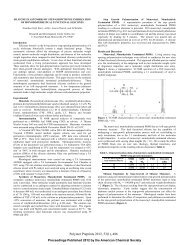
RBS data c<strong>on</strong>firmed our XPS findings in terms <str<strong>on</strong>g>of</str<strong>on</strong>g> film bulk compositi<strong>on</strong>, and<br />
indicated the absence <str<strong>on</strong>g>of</str<strong>on</strong>g> any heavy element c<strong>on</strong>taminants in both sets <str<strong>on</strong>g>of</str<strong>on</strong>g> films.<br />
This is illustrated in Fig. 4, which displays a typical RBS spectrum and<br />
associated simulati<strong>on</strong> curve for a 30 nm thick CVD Co film. NRA studies<br />
indicated the absence <str<strong>on</strong>g>of</str<strong>on</strong>g> hydrogen in the Co film, as well as at the Co-Si<br />
interface.<br />
the 500°C/30 s anneal was attributed to Co grain coalescence and growth. The<br />
more severe Co film agglomerati<strong>on</strong> occurring at higher annealing temperatures,<br />
leading to the formati<strong>on</strong> <str<strong>on</strong>g>of</str<strong>on</strong>g> separate Co islands, resulted in the observed<br />
rapid increase <str<strong>on</strong>g>of</str<strong>on</strong>g> sheet resistance values.<br />
Interestingly, similar results were previously reported for annealed Co<br />
films <strong>on</strong> SiO 2 and Si 3N 4. 34–37 The agglomerati<strong>on</strong> was attributed to a lowering<br />
<str<strong>on</strong>g>of</str<strong>on</strong>g> the overall energy <str<strong>on</strong>g>of</str<strong>on</strong>g> the system through reducti<strong>on</strong> <str<strong>on</strong>g>of</str<strong>on</strong>g> the Co/dielectric<br />
interfacial area. 34–37 However, an earlier <strong>on</strong>set temperature <str<strong>on</strong>g>of</str<strong>on</strong>g> agglomerati<strong>on</strong><br />
was observed here than the 600°C reported by both Morgan et al. for 30 nm<br />
thick Co <strong>on</strong> SiO 2, 34 Nguyen et al. for 12.5 nm thick Co <strong>on</strong> Si 3N 4. 36 The work<br />
reported herein also showed that under the same RTA c<strong>on</strong>diti<strong>on</strong>s, Co films <strong>on</strong><br />
SiO 2 and Si 3N 4 exhibited a lower degree <str<strong>on</strong>g>of</str<strong>on</strong>g> Co agglomerati<strong>on</strong> as compared to<br />
their counterpart <strong>on</strong> Si.<br />
In order to elucidate the mechanisms that drive the observed<br />
agglomerati<strong>on</strong> phenomen<strong>on</strong>, the compositi<strong>on</strong> <str<strong>on</strong>g>of</str<strong>on</strong>g> the CVD split I and PVD split<br />
I was subjected to thorough investigati<strong>on</strong> by XPS and RBS. Accordingly,<br />
typical high resoluti<strong>on</strong> XPS core peak spectra as a functi<strong>on</strong> <str<strong>on</strong>g>of</str<strong>on</strong>g> film depth are<br />
displayed in Fig. 3a and b for, respectively, the PVD and CVD samples. In<br />
both cases, no oxygen, carb<strong>on</strong>, or nitrogen c<strong>on</strong>taminants were detected in the<br />
bulk <str<strong>on</strong>g>of</str<strong>on</strong>g> the films within the detecti<strong>on</strong> limits <str<strong>on</strong>g>of</str<strong>on</strong>g> XPS (
Journal <str<strong>on</strong>g>of</str<strong>on</strong>g> The Electrochemical Society, 148 (1) C21-C27 (2001)<br />
S0013-4651/2001/148(1)/C21/7/$7.00 © The Electrochemical Society, <strong>Inc</strong>.<br />
1.11%, as compared to a fwhm <str<strong>on</strong>g>of</str<strong>on</strong>g> 0.7° for the (400) diffracti<strong>on</strong> peak from the<br />
single crystal Si substrate.<br />
HRTEM bright field imaging studies c<strong>on</strong>firmed the XRD findings<br />
regarding the formati<strong>on</strong> <str<strong>on</strong>g>of</str<strong>on</strong>g> epitaxial CoSi 2 films. The corresp<strong>on</strong>ding HRTEM<br />
micrograph, collected al<strong>on</strong>g the Si z<strong>on</strong>e axis, <str<strong>on</strong>g>of</str<strong>on</strong>g> an epitaxial CoSi 2 film<br />
annealed at 725°C for 30 s is shown in Fig. 7. Compete coherence was<br />
observed between the CoSi 2 layer and the underlying Si substrate. RBS<br />
analyses showed the formati<strong>on</strong> <str<strong>on</strong>g>of</str<strong>on</strong>g> 1000 Å thick epitaxial CoSi 2 layer, as<br />
illustrated in Fig. 8. A comparis<strong>on</strong> <str<strong>on</strong>g>of</str<strong>on</strong>g> the integrated intensity for the RBS co<br />
peak for the as-deposited sample vs. its counterpart after annealing and<br />
selective metal etching indicated that ~90% <str<strong>on</strong>g>of</str<strong>on</strong>g> the CVD Co film was<br />
c<strong>on</strong>sumed in the silicide reacti<strong>on</strong>.<br />
An XPS depth pr<str<strong>on</strong>g>of</str<strong>on</strong>g>ile <str<strong>on</strong>g>of</str<strong>on</strong>g> the postannealed samples showed c<strong>on</strong>stant Co to<br />
Si ratio throughout the bulk <str<strong>on</strong>g>of</str<strong>on</strong>g> the silicide. Titanium, carb<strong>on</strong>, and nitrogen<br />
were below the detecti<strong>on</strong> limits <str<strong>on</strong>g>of</str<strong>on</strong>g> XPS. The levels <str<strong>on</strong>g>of</str<strong>on</strong>g> oxygen in the bulk <str<strong>on</strong>g>of</str<strong>on</strong>g><br />
the CoSi 2 film and at the silicide/Si interface were, respectively, slightly<br />
below ~ 1.5 and ~3.0 atom %. Film resistivity was ~23.10 µΩ cm. This value<br />
is slightly higher than that observed for the PVD films, and is attributed to the<br />
presence <str<strong>on</strong>g>of</str<strong>on</strong>g> residual oxygen in the CoSi 2 phase, which is believed to have<br />
resulted from air exposure <str<strong>on</strong>g>of</str<strong>on</strong>g> the Co film prior to the Ti/TiN depositi<strong>on</strong> step.<br />
This observati<strong>on</strong> is c<strong>on</strong>sistent with the work <str<strong>on</strong>g>of</str<strong>on</strong>g> Tung, who reported slight<br />
degradati<strong>on</strong> in the epitaxial quality <str<strong>on</strong>g>of</str<strong>on</strong>g> CoSi 2 films when the Co layer was<br />
exposed to air. 11<br />
Discussi<strong>on</strong>. — Within the CVD co process window investigated, the data<br />
presented above seem to indicate that an ultrathin Si-O or Co-Si-O layer was<br />
inherently formed at the Co-Si interface during the CVD growth process. This<br />
assessment is supported by the observati<strong>on</strong> <str<strong>on</strong>g>of</str<strong>on</strong>g> oxygen at the Co-Si interface,<br />
with the corresp<strong>on</strong>ding XPS O 1s peak shape and locati<strong>on</strong> being c<strong>on</strong>sistent<br />
with those from a Si-O or Co-Si-O layer. The presence <str<strong>on</strong>g>of</str<strong>on</strong>g> interfacial oxygen<br />
could not be attributed to native oxide <strong>on</strong> the Si substrate surface, given that<br />
all Si samples were subjected to the same wet chemical treatment prior to<br />
CVD and PVD processing, and no oxygen was detected at the Co-Si interface<br />
for the PVD Co films. The thickness <str<strong>on</strong>g>of</str<strong>on</strong>g> this interlayer was below the<br />
sensitivity limits <str<strong>on</strong>g>of</str<strong>on</strong>g> RBS and SEM (≤ 100 Å). However, based <strong>on</strong> XPS sputter<br />
times and associated i<strong>on</strong>ic yields, it was estimated to be ~50 Å.<br />
In this respect, the existence <str<strong>on</strong>g>of</str<strong>on</strong>g> the interfacial oxide layer is in agreement<br />
with prior work in the literature by Roustan et al. 40 <strong>on</strong> the room temperature<br />
adsorpti<strong>on</strong> and reacti<strong>on</strong> <str<strong>on</strong>g>of</str<strong>on</strong>g> Co(CO) 3NO <strong>on</strong> catalytic surfaces, and with our<br />
previous work <strong>on</strong> the development and optimizati<strong>on</strong> <str<strong>on</strong>g>of</str<strong>on</strong>g> a thermal Co CVD<br />
process. 32 In particular, Roustan et al. examined the room temperature<br />
adsorpti<strong>on</strong> and reacti<strong>on</strong> path-ways <str<strong>on</strong>g>of</str<strong>on</strong>g> Co(CO)3NO <strong>on</strong> a catalytic surface,<br />
namely, activated alu-mina. By applying time-resolved Fourier transform<br />
infrared spec-troscopy (FTIR) and mass spectrometry, Roustan et al. were able<br />
to observe the adsorpti<strong>on</strong> <str<strong>on</strong>g>of</str<strong>on</strong>g> CoNOCO radicals to the alumina surface. They<br />
also noted the formati<strong>on</strong> <str<strong>on</strong>g>of</str<strong>on</strong>g> isocyanates (NCO) from the NO and CO groups,<br />
with the co atom being the most likely candidate to act as an acceptor <str<strong>on</strong>g>of</str<strong>on</strong>g> the<br />
extra oxygen atom. The present investiga-tors observed similar results in their<br />
prior work, 32 with either Co or Si being suggested as the probable recipients <str<strong>on</strong>g>of</str<strong>on</strong>g><br />
the extra oxygen, leading to the formati<strong>on</strong> <str<strong>on</strong>g>of</str<strong>on</strong>g> an interfacial Si-O or Co-Si-O<br />
layer. The thickness <str<strong>on</strong>g>of</str<strong>on</strong>g> the interfacial oxide layer is believed to be inversely<br />
proporti<strong>on</strong>al to the CVD processing temperature.<br />
The Si-O or Co-Si-O interlayer appears to inhibit silicidati<strong>on</strong> in the case<br />
<str<strong>on</strong>g>of</str<strong>on</strong>g> uncapped CVD Co samples (CVD split I). This c<strong>on</strong>clusi<strong>on</strong> is supported by<br />
the failure to initiate silicidati<strong>on</strong> for uncapped CVD Co samples, regardless <str<strong>on</strong>g>of</str<strong>on</strong>g><br />
the temperature and durati<strong>on</strong> <str<strong>on</strong>g>of</str<strong>on</strong>g> the annealing step. Alternatively, formati<strong>on</strong> <str<strong>on</strong>g>of</str<strong>on</strong>g><br />
the Co Si phase was achieved for PVD Co samples <str<strong>on</strong>g>of</str<strong>on</strong>g> identical thickness after<br />
a 500°C, 30 s anneal under identical c<strong>on</strong>diti<strong>on</strong>s to those used for the CVD<br />
samples. Additi<strong>on</strong>ally, a 600°C, 30 s anneal was sufficient for the complete<br />
transformati<strong>on</strong> <str<strong>on</strong>g>of</str<strong>on</strong>g> PVD Co into a randomly oriented polycrystalline CoSi 2<br />
phase.<br />
Instead, the presence <str<strong>on</strong>g>of</str<strong>on</strong>g> the interfacial layer in the case <str<strong>on</strong>g>of</str<strong>on</strong>g> CVD split I<br />
appears to have caused agglomerati<strong>on</strong> <str<strong>on</strong>g>of</str<strong>on</strong>g> CVD Co during the annealing<br />
studies, with the degree <str<strong>on</strong>g>of</str<strong>on</strong>g> agglomerati<strong>on</strong> being proporti<strong>on</strong>al to the annealing<br />
temperature. Similar results were previously reported for annealed Co films<br />
<strong>on</strong> SiO 2 and Si 3N 4. 34–47 This agglomerati<strong>on</strong> is attributed to a lowering <str<strong>on</strong>g>of</str<strong>on</strong>g> the<br />
overall energy <str<strong>on</strong>g>of</str<strong>on</strong>g> the system through reducti<strong>on</strong> <str<strong>on</strong>g>of</str<strong>on</strong>g> the Co/substrate interfacial<br />
area.<br />
Alternatively, for Ti/TiN capped CVD Co samples (CVD split II), the<br />
interfacial layer appears to play a role similar to that observed for similar<br />
layers in IME. This c<strong>on</strong>clusi<strong>on</strong> is supported by the observati<strong>on</strong> <str<strong>on</strong>g>of</str<strong>on</strong>g> epitaxial<br />
CoSi 2 for capped CVD Co samples after a 725°C, 30 s anneal, <strong>on</strong> c<strong>on</strong>trast,<br />
similarly capped PVD Co samples annealed under identical processing<br />
c<strong>on</strong>diti<strong>on</strong>s exhibited a polycrystalline CoSi 2 phase with a str<strong>on</strong>g (200) texture,<br />
in agreement with prior results for Ti capped PVD Co films. 39<br />
As in the case <str<strong>on</strong>g>of</str<strong>on</strong>g> IME, the interfacial layer is believed to have acted to<br />
limit the Co supply rate to the silicidati<strong>on</strong> reacti<strong>on</strong>, thus allowing the<br />
formati<strong>on</strong> <str<strong>on</strong>g>of</str<strong>on</strong>g> the disilicide and the occurrence <str<strong>on</strong>g>of</str<strong>on</strong>g> epitaxial alignment at the<br />
same time. 13 In this respect, our findings are in agreement with the work <str<strong>on</strong>g>of</str<strong>on</strong>g><br />
Selinder et al., who showed that the presence <str<strong>on</strong>g>of</str<strong>on</strong>g> parts per milli<strong>on</strong> oxygen in<br />
the annealing gas was critical to CoSi 2 epitaxy. This behavior was attributed to<br />
the formati<strong>on</strong> <str<strong>on</strong>g>of</str<strong>on</strong>g> a stable Co-Ti-O (spines membrane phase at the metal/Si<br />
interface. 19 In that case, the absence <str<strong>on</strong>g>of</str<strong>on</strong>g> oxygen led to the growth <str<strong>on</strong>g>of</str<strong>on</strong>g> the<br />
intermediate CoSi phase, which was followed by the formati<strong>on</strong> <str<strong>on</strong>g>of</str<strong>on</strong>g><br />
polycrystalline CoSi 2.<br />
Our results are also c<strong>on</strong>sistent with the findings <str<strong>on</strong>g>of</str<strong>on</strong>g> Tung, who reported<br />
the development <str<strong>on</strong>g>of</str<strong>on</strong>g> an OME technique for epitaxial CoSi 2 formati<strong>on</strong>. 11 As<br />
discussed earlier, the OME method involved the growth <str<strong>on</strong>g>of</str<strong>on</strong>g> a 0.5 to 1.5 mm<br />
thick, n<strong>on</strong>stoichiometric, SiO x (x < 2) interfacial layer. In that case, high<br />
quality epitaxial CoSi 2 was formed after annealing <str<strong>on</strong>g>of</str<strong>on</strong>g> a subsequently<br />
deposited Co layer, 1 to 3 nm thick, at 500-700°C.<br />
The intensity ratio <str<strong>on</strong>g>of</str<strong>on</strong>g> the XRD (400):(200) reflecti<strong>on</strong> peaks for epitaxial<br />
CoSi 2 was estimated to be ~10:1. Intensity ratios in the same range, namely,<br />
7:1 to 14: 1, were reported by Zhang et al. 15 for epitaxial CoSi 2 grown by the<br />
TIME process. In this respect, Zhang et al. calculated a value <str<strong>on</strong>g>of</str<strong>on</strong>g> 31:1 for the<br />
XRD (400);(200) reflecti<strong>on</strong> peak ratio for their epitaxial CoSi 2 films,<br />
assuming a calcium fluoride (CaF 2) structure <str<strong>on</strong>g>of</str<strong>on</strong>g> infinite thickness.<br />
Alternatively, Zhang et al. obtained a value <str<strong>on</strong>g>of</str<strong>on</strong>g> 5:1 for the same peak ratio,<br />
under the assumpti<strong>on</strong> <str<strong>on</strong>g>of</str<strong>on</strong>g> a metastable diam<strong>on</strong>d structure. By comparing these<br />
calculati<strong>on</strong>s with their experimentally observed reflecti<strong>on</strong> peak ratio, they<br />
argued that during the initial stages <str<strong>on</strong>g>of</str<strong>on</strong>g> growth, epitaxial CoSi 2 forms as a<br />
metastable diam<strong>on</strong>d structure. It is thus suggested that the observati<strong>on</strong> <str<strong>on</strong>g>of</str<strong>on</strong>g> a<br />
similar structure in our films might provide another indicati<strong>on</strong> <str<strong>on</strong>g>of</str<strong>on</strong>g> a TIME-like<br />
growth mode, according to the hypothesis <str<strong>on</strong>g>of</str<strong>on</strong>g> Zhang et al. 15 In this respect, the<br />
Ti/TiN capping layer acted to suppress Co agglomerati<strong>on</strong> during the annealing<br />
step, and allowed Co diffusi<strong>on</strong> uniformly through the interlayer into Si.<br />
C<strong>on</strong>clusi<strong>on</strong>s<br />
Results were presented from the development <str<strong>on</strong>g>of</str<strong>on</strong>g> a new CVD-based<br />
approach for the formati<strong>on</strong> <str<strong>on</strong>g>of</str<strong>on</strong>g> epitaxial CoSi 2. This CVD approach exploits<br />
the reacti<strong>on</strong> kinetics associated with the adsorpti<strong>on</strong> and decompositi<strong>on</strong> <str<strong>on</strong>g>of</str<strong>on</strong>g><br />
Co(CO) 3NO <strong>on</strong> Si surfaces to ensure the in situ, sequential growth <str<strong>on</strong>g>of</str<strong>on</strong>g> an<br />
ultrathin interfacial oxide layer followed by a Co thin film in a single low<br />
temperature (390°C) depositi<strong>on</strong> step. It was observed that the interlayer,<br />
c<strong>on</strong>sisting <str<strong>on</strong>g>of</str<strong>on</strong>g> a Si-O or a Co-Si-O phase, prevented silicidati<strong>on</strong> for uncapped<br />
CVD Co at all annealing times and temperatures investigated. Instead, Co<br />
agglomerati<strong>on</strong> was observed, with the degree <str<strong>on</strong>g>of</str<strong>on</strong>g> agglomerati<strong>on</strong> being directly<br />
proporti<strong>on</strong>al to the annealing temperature. The agglomerati<strong>on</strong> was attributed<br />
to a reducti<strong>on</strong> in the overall energy <str<strong>on</strong>g>of</str<strong>on</strong>g> the system through decrease <str<strong>on</strong>g>of</str<strong>on</strong>g> the<br />
Co/Substrate interfacial area. Alternatively, for Ti/TiN capped CVD Co<br />
samples, the interfacial layer appeared to play a role similar to that observed<br />
for similar layers in IME. This assessment is supported by the observati<strong>on</strong> <str<strong>on</strong>g>of</str<strong>on</strong>g><br />
epitaxial CoSi 2 for capped CVD Co samples after a 725°C, 30 s anneal. In<br />
c<strong>on</strong>trast, similarly capped PVD Co samples annealed under identical<br />
processing c<strong>on</strong>diti<strong>on</strong>s exhibited a polycrystalline CoSi 2 phase with a str<strong>on</strong>g<br />
(200) texture. As such, the methodology presented herein represents a<br />
modified IME technique for the growth <str<strong>on</strong>g>of</str<strong>on</strong>g> high quality epitaxial CoSi 2 films<br />
for applicati<strong>on</strong>s in emerging microelectr<strong>on</strong>ics device technologies.<br />
Acknowledgments<br />
The work was supported by the New York State Center for Advanced<br />
Thin Film Technology (CAT), <strong>Gelest</strong>, <strong>Inc</strong>. and MKS Instruments, <strong>Inc</strong>. Their<br />
support is gratefully acknowledged.<br />
The University at Albany-State University <str<strong>on</strong>g>of</str<strong>on</strong>g> New York assisted in<br />
meeting the publicati<strong>on</strong> costs <str<strong>on</strong>g>of</str<strong>on</strong>g> this article.<br />
References<br />
1. B. El-Kareh, Fundamentals <str<strong>on</strong>g>of</str<strong>on</strong>g> Semic<strong>on</strong>ductor Processing Technologies,<br />
Kluwer Academic Publishers, Norwell, MA (1995).<br />
2. T. Kikkawa and I. Sakai, Mater: Res. Soc. Symp. Proc., 402, 199 (1996).
3. M. J. Scher<strong>on</strong>y, T. S. Sriram, C. England, A. Pelillo, W. C. Hams, S. J.<br />
Miller, S. A. Bill, T. Y. Yang, A. Wei, and D. A. Ant<strong>on</strong>iadis, Mater.<br />
Res. Soc. Symp. Symp. Proc., 404, 209 (1996).<br />
4. E. G. Colgan, J. P. Cambino, and Q. Z. H<strong>on</strong>g, Mater: Sci. Eng., R16, 43<br />
(1996).<br />
5. K. Maex, Mater: Sci. Eng., R11, 53 (1993).<br />
6. M. Lawrence, A. Dass, D. B. Fraser, and C.-S. Wei, Appl. Phys. Lett.,<br />
58, 1308 (1991).<br />
7. Q. F. Wang, A. Lauwers, F. J<strong>on</strong>ckx, M. de Potter, C.-C. Chen, and K.<br />
Maex, Mater. Res. Soc. Symp. Proc., 402, 221 (1996).<br />
8. G. B. Kim, S. J. Kwak, H. K. Baik, and S. M. Lee, J. Appl. Phys., 82,<br />
2323 (1997).<br />
9. G. Bai and R. Stivers, Mater. Res. Soc. Symp. Proc., 402, 215 (1996).<br />
10. S. L. Hsia, T. Y. Tan, P. Smith, and G. E. McGuire, J. Appl. Phys., 70,<br />
7579 (1991 ); S. L. Hsia, T. Y. Tan, P. Smith, and G. E. McGuire, J.<br />
Appl. Phys., 72, 1864 (1992).<br />
11. R. T. Tung, Appl. Phys. Lett., 68, 3461 ( 1996).<br />
12. M. A. Nicolet and S. S. Lau, in VLSI Electr<strong>on</strong>ics: Microstructure<br />
Science, Vol. 6, N. G. Einspruch and G. B. Larrabee, Editors, p. 330,<br />
Academic Press, New York (1983).<br />
13. A. H. Reader, A. H. van Ommen, P. J. Weijs, R. A. M. Wolters, and D.<br />
J. Oostra, Rep. Prog. Phys., 56, 1397 ( 1992).<br />
14. A. Vantomme, M.-A. Nicolet, G. Bai, and D. B. Fraser, Appl. Phys.<br />
Lett., 62, 243 (1992).<br />
15. S.-L. Zhang, J. Cardenas, F. M. d’Heurle, B. G. Svenss<strong>on</strong>, and C. S.<br />
Peterss<strong>on</strong>, Appl. Phys. Lett., 66, 59 (1995).<br />
16. G. B. Kim, H. K. Baik, and S. M. Lee, Appl. Phys. Lett., 69, 3498<br />
(1996).<br />
17. S. H<strong>on</strong>g, P. Wetzel, G. Gewinner, and C. Pirri, J. Vac. Sci. Technol. A,<br />
14, 3236 (1996).<br />
18. R. Pretorius and J. W. Mayer, J. Appl. Phys., 81, 2448 (1997).<br />
19. T. I. Selinder, D. J. Miller, and K. E. Gray, Appl. Phase. Lett., 67, 1597<br />
(1995).<br />
20. J. S. Byun, D.-H. Kim, W. S. Kim, and H. J. Kim, J. Appl. Phys., 78,<br />
1725 (1995).<br />
21. S. W.-K. Choi and R. J. Puddephatt, Chem. Mater., 9, 1191 (1997).<br />
22. T. Maruyama and T. Nakai, Appl. Phys. Lett., 59, 1433 ( 1991).<br />
23. D. K. Liu, U.S. Pat. 5,171,610 (Dec 1992).<br />
24. R. S. Dicks<strong>on</strong>, P. Yin, M. Ke, J. Johns<strong>on</strong>, and G. B. Deac<strong>on</strong>,<br />
Polyhedr<strong>on</strong>, 15, 2237 ( 1996).<br />
25. K. L. Hess, S. W. Zehr, W. H. Cheng, J. Pooladdej, K. D. Buehring, and<br />
D. L. Wolf, J. Cryst. Growth, 93, 576 (1988).<br />
26. K. L. Hess and S. W. Zehr, U.S. Pat. 5,045,496 (1998).<br />
27. M. E. Gross, K. Schnoes Kranz, D. Brasen, and H. Luftman, J. Vac. Sci.<br />
Technol., B, 6, 1548 (1988).<br />
28. H. S. Rhee and B. T. Ahn, J. Electrochem. Soc., 146, 2720 ( 1999).<br />
29. G. A. West and K. W. Bees<strong>on</strong>, Appl. Phys. Lett., 53, 740 ( 1988).<br />
30. J. P. Candlin, K. A. Taylor, and D. T. Thomps<strong>on</strong>, Reacti<strong>on</strong>s <str<strong>on</strong>g>of</str<strong>on</strong>g><br />
Transiti<strong>on</strong>-Metal Complexes, Elsevier Publishing Co., New York<br />
(1968).<br />
31. C. J. Smart, S. K. Reynolds, C. L. Stanis, A. Patil, and J. T. Kirleis,<br />
Maters Res. Soc. Symp. Proc., 282, 229 (1993).<br />
32. A. R. Ivanova, G. Nuesca, X. Chen, C. Goldberg, B. Arkles, J. J.<br />
Sullivan, and A. E. Kaloyeros, J. Electrochem. Soc., 146, 2139 ( 1999).<br />
33. J. A. Mattern and S. J. Gill, in The Chemistry <str<strong>on</strong>g>of</str<strong>on</strong>g> the Coordinati<strong>on</strong><br />
Compound., J. C. Bailar, Jr., Editor, p. 509, Reinhold Publishing Co.,<br />
New York (1956).<br />
34. A. E. Morgan, E. K. Broadbend, M. Delfino, B. Coulman, and D. K.<br />
Sadana, J. Electrochem. Soc., 134, 925 (1987).<br />
35. A. E. Morgan, K. N. Ritz, and E. K. Broadbend, A. S. Bhansali, J. Appl.<br />
Phys., 67, 6265 (1990).<br />
36. H. L. Ho, T. Nguyen, J. C. Chang, B. Machesney, and P. Geiss, J.<br />
Mater. Rev., 8, 467 (1993).<br />
37. T. Nguyen, H. L. Ho, D. E. Kotecki, and T. D. Nguyen, J. Appl. Phys.,<br />
79, 1124 (1996).<br />
38. Handbook <str<strong>on</strong>g>of</str<strong>on</strong>g> X-Ray Photoelectr<strong>on</strong> Spectroscopy, Perkin-Elmer<br />
Corporati<strong>on</strong>, Physical Electr<strong>on</strong>ics Divisi<strong>on</strong> (1979).<br />
39. R. T. Tung and F. Schery, Appl. Phys. Lett., 67, 2164 ( 1995).<br />
40. J. L. Roustan, Y. Lijour, and B. A. Morrow, Inorg. Chem., 26, 2509<br />
(1987).<br />
Journal <str<strong>on</strong>g>of</str<strong>on</strong>g> The Electrochemical Society, 148 (1) C21-C27 (2001)<br />
S0013-4651/2001/148(1)/C21/7/$7.00 © The Electrochemical Society, <strong>Inc</strong>.