Barcodescanner CLV62x ... CLV64x mit Schutzgehäuse IP ... - Sick
Barcodescanner CLV62x ... CLV64x mit Schutzgehäuse IP ... - Sick Barcodescanner CLV62x ... CLV64x mit Schutzgehäuse IP ... - Sick
Anschluss „Ethernet“ / “Ethernet“ connection 4 1 3 2 4-pol. M12-Dose, D-codiert 4-pin M12 socket, D-coded Pin Signal Funktion Function 1 TD+ Sender+ Transmitter+ 2 RD+ Empfänger+ Receiver+ 3 TD– Sender– Transmitter– 4 RD– Empfänger– Receiver– Tabelle 2/Table 2 7.2 Pin- und Aderfarbbelegungen von Leitungen Anschluss „Power/serial data/CAN/I/O“ an kundenspezifische Anschaltevorrichtung (Netzteil) 7.2 Pin Assignments and Lead Color Assignments of Cables “Power/serial data/CAN/I/O” connection to customer-specific connection box (power supply unit) Nr./no. 2070425 (3 m), Nr./no 2070426 (5 m), Nr./no. 2070427 (10 m) ... 17-pol. M12-Buchse, A-codiert (Ansicht von vorne) 17-pin M12 socket, A-coded (front view) Pin Signal Aderfarbe Lead color 1 GND Blau Blue 2 DC 18 ... 30 V*) Braun Brown 3 CAN L Grün Green 4 CAN H Weiß White 5 TD+ (RS-422/485) Rosa Pink 6 TD– (RS-422/485)/TxD (RS-232 Gelb Yellow 7 TxD (RS-232) Schwarz Black 8 RxD (RS-232) Grau Gray 9 SensGND Weiß + schwarz Black + white 10 Sensor 1 Violett Purple 11 RD+ (RS-422/485) Grau + rosa Gray + pink 12 RD– (RS-422/485)/RxD (RS-232) Rot + blau Red + blue 13 Result 1 Weiß + grün White + green 14 Result 2 Braun + grün Brown + green 15 Sensor 2 Weiß + gelb White + yellow 16 – Gelb + braun (nicht anschließen!) Yellow + brown (do not connect!) 17 – Weiß + grau (nicht anschließen!) White + gray (do not connect!) *) CLV62x: DC 10 ... 30 V Tabelle 3/Table 3 12 # 24 © SICK AG · Germany · All rights reserved · Subject to change without notice · Irrtümer und Änderungen vorbehalten 8015720/2013-04
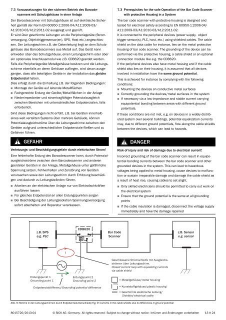
7.3 Voraussetzungen für den sicheren Betrieb des Barcodescanners mit Schutzgehäuse in einer Anlage Der Barcodescanner mit Schutzgehäuse ist auf elektrische Sicherheit gemäß der Norm EN 60950-1:2006-04/A11:2009-03/ A1:2010-03/A12:2011-02 ausgelegt und geprüft. Er wird über geschirmte Leitungen an die Peripheriegeräte (Stromversorgung, Objekttriggersensor(en), SPS, Host etc.) angeschlossen. Der Leitungsschirm z.B. der Datenleitung liegt an dem Schutzgehäuse des Barcodescanners aus Metall auf. Das Gerät kann entweder über das Schutzgehäuse, einen Leitungsschirm oder über ein optionales Anschlussmodul wie z.B. CDB620 geerdet werden. Falls die Peripheriegeräte Metallgehäuse besitzen und die Leitungsschirme ebenfalls an deren Gehäuse aufliegen, wird davon ausgegangen, dass alle beteiligten Geräte in der Installation das gleiche Erdpotenzial haben. Dies erfolgt durch die Einhaltung z.B. der folgenden Bedingungen: ■ Montage der Geräte auf leitende Metallflächen ■ Fachgerechte Erdung der Geräte/Metallflächen in der Anlage ■ Niederimpedanter und stromtragfähiger Potenzialausgleich zwischen Bereichen mit unterschiedlichen Erdpotenzialen, falls erforderlich. Sind diese Bedingungen nicht erfüllt, z.B. bei Geräten innerhalb eines weit verteilten Systems über mehrere Gebäude, können Potentialausgleichströme über die Leitungsschirme zwischen den Geräten aufgrund unterschiedlicher Erdpotenziale fließen und zu Gefahren führen. GEFAHR Verletzungs- und Beschädigungsgefahr durch elektrischen Strom! Eine fehlerhafte Erdung des Barcodescanner kann, durch Potenzialausgleichsströme zwischen dem Barcodescanner und anderen geerdeten Geräten in der Anlage, Metallgehäuse unter gefährliche Spannung setzen, Fehlverhalten und Zerstörung von Geräten verursachen sowie den Leitungsschirm durch Erhitzung beschädigen und dadurch zu Leitungsbränden führen. ■ Arbeiten an der elektrischen Anlage nur von Elektrofachkräften ausführen lassen ■ Für gleiches Erdpotenzial an allen Erdungspunkten sorgen ■ Bei Beschädigung der Leitungsisolation Spannungsversorgung sofort abschalten und Reparatur veranlassen. 7.3 Prerequisites for the safe Operation of the Bar Code Scanner with protective Housing in a System The bar code scanner with protective housing is designed and tested for electrical safety according to EN 60950-1:2006-04/ A11:2009-03/A1:2010-03/A12:2011-02. It is connected to the peripheral devices (power supply, object trigger sensor(s), PLC, host, etc.) using shielded cables. The cable shield on the data cable for instance, lies on the metal protective housing of bar code scanner. The grounding of the device can be performed via the protective housing, a cable shield or an optional connection module like e.g. the CDB620. If the peripheral devices also have metal housing and if the cable shield also lies on their housing, it is assumed that all devices involved in installation have the same ground potential. This is achieved for instance by complying with the following conditions: ■ Mounting the devices on conductive metal surfaces ■ Correctly grounding the devices/metal surfaces in the system ■ If necessary via a low-impedance and stable current carrying equipotential bonding between areas with different ground potentials. If these conditions are not met, e.g. on devices in a widely distributed system over several buildings, potential equalization currents may, due to different ground potentials, flow along the cable shields between the devices, which can lead to hazards. DANGER Risk of injury and risk of damage due to electrical current! Incorrect grounding of the bar code scanner can result in equipotential bonding currents between the bar code scanner and other grounded devices in the system. This can lead to hazardous voltages being applied to metal housing, cause devices to malfunction or sustain irreparable damage and damage the cable shield as a result of heat rise, causing cables to set alight. ■ Only skilled electricians should be permitted to carry out work on the electrical system ■ Ensure that the ground potential is the same at all grounding points ■ If the cable insulation is damaged, disconnect the voltage supply immediately and have the damage repaired z.B. SPS e.g. PLC CDB620 Bar Code Scanner z.B. Sensor e.g. sensor I Geschlossene Stromschleife mit Ausgleichsströmen über Leitungsschirm. Closed current loop with equalizing currents via cable shield Erdungspunkt 1 Grounding point 1 U Erdungspunkt 2 Grounding point 2 = Metallgehäuse/metal housing Erdpotenzialdifferenz/Grounding potential difference = Kunststoffgehäuse/plastic housing = Geschirmte elektrische Leitung/ Shielded electrical cable Abb. 9: Ströme in den Leitungsschirmen durch Erdpotentialunterschiede/Fig. 9: Currents in the cable shields due to differences in ground potential 8015720/2013-04 © SICK AG · Germany · All rights reserved · Subject to change without notice · Irrtümer und Änderungen vorbehalten 13 # 24
- Page 1 and 2: Barcodescanner CLV62x ... CLV64x mi
- Page 3 and 4: ■ ■ Gegenüber den Standardger
- Page 5 and 6: 6. Montage Grundsätzliche Vorgehen
- Page 7 and 8: 6.2 Schutzgehäuse vorbereiten WICH
- Page 9 and 10: a) Stopfen belassen und auf festen
- Page 11: WICHTIG! Das in der Konfigurationss
- Page 15 and 16: Metallgehäuse/Metal housing Geschi
- Page 17 and 18: jeweils gültigen länderspezifisch
- Page 19 and 20: 13. Bestellinformationen 13.1 Barco
- Page 21 and 22: 88.5 29.2 52.5 30 4 x Bohrung / dri
- Page 23 and 24: 137 71,5 21 20 42 Ø 20,2 für Rund
7.3 Voraussetzungen für den sicheren Betrieb des <strong>Barcodescanner</strong>s<br />
<strong>mit</strong> <strong>Schutzgehäuse</strong> in einer Anlage<br />
Der <strong>Barcodescanner</strong> <strong>mit</strong> <strong>Schutzgehäuse</strong> ist auf elektrische Sicherheit<br />
gemäß der Norm EN 60950-1:2006-04/A11:2009-03/<br />
A1:2010-03/A12:2011-02 ausgelegt und geprüft.<br />
Er wird über geschirmte Leitungen an die Peripheriegeräte (Stromversorgung,<br />
Objekttriggersensor(en), SPS, Host etc.) angeschlossen.<br />
Der Leitungsschirm z.B. der Datenleitung liegt an dem <strong>Schutzgehäuse</strong><br />
des <strong>Barcodescanner</strong>s aus Metall auf. Das Gerät kann<br />
entweder über das <strong>Schutzgehäuse</strong>, einen Leitungsschirm oder über<br />
ein optionales Anschlussmodul wie z.B. CDB620 geerdet werden.<br />
Falls die Peripheriegeräte Metallgehäuse besitzen und die Leitungsschirme<br />
ebenfalls an deren Gehäuse aufliegen, wird davon ausgegangen,<br />
dass alle beteiligten Geräte in der Installation das gleiche<br />
Erdpotenzial haben.<br />
Dies erfolgt durch die Einhaltung z.B. der folgenden Bedingungen:<br />
■ Montage der Geräte auf leitende Metallflächen<br />
■ Fachgerechte Erdung der Geräte/Metallflächen in der Anlage<br />
■ Niederimpedanter und stromtragfähiger Potenzialausgleich<br />
zwischen Bereichen <strong>mit</strong> unterschiedlichen Erdpotenzialen, falls<br />
erforderlich.<br />
Sind diese Bedingungen nicht erfüllt, z.B. bei Geräten innerhalb<br />
eines weit verteilten Systems über mehrere Gebäude, können<br />
Potentialausgleichströme über die Leitungsschirme zwischen den<br />
Geräten aufgrund unterschiedlicher Erdpotenziale fließen und zu<br />
Gefahren führen.<br />
GEFAHR<br />
Verletzungs- und Beschädigungsgefahr durch elektrischen Strom!<br />
Eine fehlerhafte Erdung des <strong>Barcodescanner</strong> kann, durch Potenzialausgleichsströme<br />
zwischen dem <strong>Barcodescanner</strong> und anderen<br />
geerdeten Geräten in der Anlage, Metallgehäuse unter gefährliche<br />
Spannung setzen, Fehlverhalten und Zerstörung von Geräten<br />
verursachen sowie den Leitungsschirm durch Erhitzung beschädigen<br />
und dadurch zu Leitungsbränden führen.<br />
■ Arbeiten an der elektrischen Anlage nur von Elektrofachkräften<br />
ausführen lassen<br />
■ Für gleiches Erdpotenzial an allen Erdungspunkten sorgen<br />
■ Bei Beschädigung der Leitungsisolation Spannungsversorgung<br />
sofort abschalten und Reparatur veranlassen.<br />
7.3 Prerequisites for the safe Operation of the Bar Code Scanner<br />
with protective Housing in a System<br />
The bar code scanner with protective housing is designed and<br />
tested for electrical safety according to EN 60950-1:2006-04/<br />
A11:2009-03/A1:2010-03/A12:2011-02.<br />
It is connected to the peripheral devices (power supply, object<br />
trigger sensor(s), PLC, host, etc.) using shielded cables. The cable<br />
shield on the data cable for instance, lies on the metal protective<br />
housing of bar code scanner. The grounding of the device can be<br />
performed via the protective housing, a cable shield or an optional<br />
connection module like e.g. the CDB620.<br />
If the peripheral devices also have metal housing and if the cable<br />
shield also lies on their housing, it is assumed that all devices<br />
involved in installation have the same ground potential.<br />
This is achieved for instance by complying with the following<br />
conditions:<br />
■ Mounting the devices on conductive metal surfaces<br />
■ Correctly grounding the devices/metal surfaces in the system<br />
■ If necessary via a low-impedance and stable current carrying<br />
equipotential bonding between areas with different ground<br />
potentials.<br />
If these conditions are not met, e.g. on devices in a widely distributed<br />
system over several buildings, potential equalization currents<br />
may, due to different ground potentials, flow along the cable shields<br />
between the devices, which can lead to hazards.<br />
DANGER<br />
Risk of injury and risk of damage due to electrical current!<br />
Incorrect grounding of the bar code scanner can result in equipotential<br />
bonding currents between the bar code scanner and other<br />
grounded devices in the system. This can lead to hazardous<br />
voltages being applied to metal housing, cause devices to malfunction<br />
or sustain irreparable damage and damage the cable shield as<br />
a result of heat rise, causing cables to set alight.<br />
■ Only skilled electricians should be per<strong>mit</strong>ted to carry out work on<br />
the electrical system<br />
■ Ensure that the ground potential is the same at all grounding<br />
points<br />
■ If the cable insulation is damaged, disconnect the voltage supply<br />
immediately and have the damage repaired<br />
z.B. SPS<br />
e.g. PLC<br />
CDB620<br />
Bar Code<br />
Scanner<br />
z.B. Sensor<br />
e.g. sensor<br />
I<br />
Geschlossene Stromschleife <strong>mit</strong> Ausgleichsströmen<br />
über Leitungsschirm.<br />
Closed current loop with equalizing currents<br />
via cable shield<br />
Erdungspunkt 1<br />
Grounding point 1<br />
U<br />
Erdungspunkt 2<br />
Grounding point 2<br />
= Metallgehäuse/metal housing<br />
Erdpotenzialdifferenz/Grounding potential difference<br />
= Kunststoffgehäuse/plastic housing<br />
= Geschirmte elektrische Leitung/<br />
Shielded electrical cable<br />
Abb. 9: Ströme in den Leitungsschirmen durch Erdpotentialunterschiede/Fig. 9: Currents in the cable shields due to differences in ground potential<br />
8015720/2013-04 © SICK AG · Germany · All rights reserved · Subject to change without notice · Irrtümer und Änderungen vorbehalten<br />
13 # 24


