
You also want an ePaper? Increase the reach of your titles
YUMPU automatically turns print PDFs into web optimized ePapers that Google loves.
DATA PROJECTOR<br />
MODEL<br />
<strong>XG</strong>-<strong>PH80W</strong>-N<br />
<strong>XG</strong>-PH80X-N<br />
OPERATION MANUAL<br />
Introduction Easy Start Setup Connections<br />
Basic<br />
<strong>Operation</strong><br />
Useful<br />
Features<br />
Appendix
IMPORTANT<br />
• For your assistance in reporting the loss<br />
or theft of your Projector, please record<br />
the Model and Serial Number located on<br />
the bottom of the projector and retain this<br />
information.<br />
• Before recycling the packag ing, please<br />
ensure that you have checked the contents<br />
of the carton thoroughly against the<br />
list of “Supplied accessories” on page 11.<br />
Model No.:<br />
Serial No.:<br />
ii
SPECIAL NOTE FOR USERS IN THE U.K.<br />
The mains lead of this product is fi tted with a non-rewireable (moulded) plug incorporating<br />
a 10A fuse. Should the fuse need to be replaced, a BSI or ASTA approved BS 1362 fuse<br />
marked or and of the same rating as above, which is also indicated on the pin face<br />
of the plug, must be used.<br />
Always refi t the fuse cover after replacing the fuse. Never use the plug without the fuse<br />
cover fi tted.<br />
In the unlikely event of the socket outlet in your home not being compatible with the plug<br />
supplied, cut off the mains plug and fi t an appropriate type.<br />
DANGER:<br />
The fuse from the cut-off plug should be removed and the cut-off plug destroyed immediately<br />
and disposed of in a safe manner.<br />
Under no circumstances should the cut-off plug be inserted elsewhere into a 13A socket<br />
outlet, as a serious electric shock may occur.<br />
To fi t an appropriate plug to the mains lead, follow the instructions below:<br />
WARNING:<br />
THIS APPARATUS MUST BE EARTHED.<br />
IMPORTANT:<br />
The wires in this mains lead are coloured in accordance with the following code:<br />
Green-and-yellow : Earth<br />
Blue<br />
: Neutral<br />
Brown<br />
: Live<br />
As the colours of the wires in the mains lead of this apparatus may not correspond with<br />
the coloured markings identifying the terminals in your plug proceed as follows:<br />
The wire which is coloured green-and-yellow must be connected to the terminal in the<br />
plug which is marked by the letter E or by the safety earth symbol or coloured green<br />
or green-and-yellow.<br />
The wire which is coloured blue must be connected to the terminal which is marked<br />
with the letter N or coloured black.<br />
The wire which is coloured brown must be connected to the terminal which is marked<br />
with the letter L or coloured red.<br />
IF YOU HAVE ANY DOUBT, CONSULT A QUALIFIED ELECTRICIAN.<br />
Authorized representative responsible for the European Union Community Market<br />
SHARP ELECTRONICS (Europe) GmbH<br />
Sonninstraße 3, D-20097 Hamburg<br />
E.U. ONLY<br />
iii
The supplied CD-ROM contains operation instructions in English, German, French, Spanish,<br />
Italian, Dutch, Swedish, Portuguese, Chinese, Korean and Arabic. Carefully read through the<br />
operation instructions before operating the projector.<br />
Die mitgelieferte CD-ROM enthält Bedienungsanleitungen in Englisch, Deutsch, Französisch,<br />
Spanisch, Italienisch, Niederländisch, Schwedisch, Portugiesisch, Chinesisch, Koreanisch<br />
und Arabisch. Bitte lesen Sie die Bedienungsanleitung vor der Verwendung des Projektors<br />
sorgfältig durch.<br />
Le CD-ROM fourni contient les instructions de fonctionnement en anglais, allemand, français,<br />
espagnol, italien, néerlandais, suédois, portugais, chinois, coréen et arabe. Veuillez lire attentivement<br />
ces instructions avant de faire fonctionner le projecteur.<br />
El CD-ROM suministrado contiene instrucciones de operación en inglés, alemán, francés,<br />
español, italiano, holandés, sueco, portugués, chino, coreano y árabe. Lea cuidadosamente<br />
las instrucciones de operación antes de utilizar el proyector.<br />
Il CD-ROM in dotazione contiene istruzioni per l’uso in inglese, tedesco, francese, spagnolo,<br />
italiano, olandese, svedese, portoghese, cinese, coreano e arabo. Leggere attentamente le<br />
istruzioni per l’uso prima di usare il proiettore.<br />
De meegeleverde CD-ROM bevat handleidingen in het Engels, Duits, Frans, Spaans,<br />
Italiaans, Nederlands, Zweeds, Portugees, Chinees, Koreaans en Arabisch. Lees de<br />
handleiding zorgvuldig door voor u de projector in gebruik neemt.<br />
Den medföljande CD-ROM-skivan innehåller bruksanvisningar på engelska, tyska, franska,<br />
spanska, italienska, holländska, svenska, portugisiska, kinesiska, koreanska och arabiska.<br />
Läs noga igenom bruksanvisningen innan projektorn tas i bruk.<br />
O CD-ROM fornecido contém instruções de operação em Inglês, Alemão, Francês,<br />
Espanhol, Italiano, Holandês, Sueco, Português, Chinês, Coreano e Árabe. Leia<br />
cuidadosamente todas as instruções de operação antes de operar o projetor.<br />
iv
Before using the projector, please read this operation manual carefully.<br />
Introduction<br />
ENGLISH<br />
There are two important reasons for prompt warranty registration of your new<br />
SHARP Projec tor, using the REGISTRATION CARD packed with the projector.<br />
1. WARRANTY<br />
This is to assure that you immediately receive the full benefit of the parts,<br />
service and labor warranty applicable to your purchase.<br />
2. CONSUMER PRODUCT SAFETY ACT<br />
To ensure that you will promptly receive any safety notifi cation of inspection,<br />
modification, or recall that SHARP may be required to give under the 1972<br />
Consumer Product Safety Act, PLEASE READ CAREFULLY THE IMPORTANT<br />
“LIMITED WARRANTY” CLAUSE.<br />
U.S.A. ONLY<br />
Introduction<br />
WARNING: High brightness light source. Do not stare into the beam of light, or view<br />
directly. Be especially careful that children do not stare directly into the<br />
beam of light.<br />
WARNING: To reduce the risk of fi re or electric shock, do not<br />
expose this product to rain or mois ture.<br />
See bottom of projector.<br />
CAUTION<br />
RISK OF ELECTRIC SHOCK.<br />
DO NOT REMOVE SCREWS<br />
EXCEPT SPECIFIED USER<br />
SERVICE SCREW.<br />
CAUTION: TO REDUCE THE RISK OF ELECTRIC SHOCK,<br />
DO NOT REMOVE COVER.<br />
NO USER-SERVICEABLE PARTS EXCEPT LAMP UNIT.<br />
REFER SERVICING TO QUALIFIED SERVICE<br />
PERSONNEL.<br />
The lightning fl ash with arrowhead symbol,<br />
within an equilateral triangle, is intended<br />
to alert the user to the presence<br />
of uninsulated “dangerous voltage”<br />
within the product's enclosure that may<br />
be of suffi cient magnitude to constitute<br />
a risk or electric shock to persons.<br />
The exclamation point within a triangle<br />
is intended to alert the user to the presence<br />
of important operating and maintenance<br />
(servicing) instructions in the<br />
literature accompanying the product.<br />
WARNING:<br />
This is a Class A product. In a domestic environment this product may cause<br />
radio interference in which case the user may be required to take adequate<br />
measures.<br />
WARNING: FCC Regulations state that any unauthorized changes or modifi cations<br />
to this equipment not expressly approved by the manufacturer could<br />
void the user's authority to operate this equip ment.<br />
U.S.A. ONLY<br />
The enclosed computer cable must be used with the device. The cable is<br />
provided to ensure that the device complies with FCC Class A verifi cation.<br />
U.S.A. ONLY<br />
1
INFORMATION<br />
This equipment has been tested and found to comply with the limits for a Class A<br />
digital device, pursuant to Part 15 of the FCC Rules. These limits are designed to<br />
provide reasonable protection against harmful interference when the equipment is<br />
operated in a commercial environment. This equipment generates, uses, and can<br />
radiate radio frequency energy and, if not installed and used in accordance with<br />
the operation manual, may cause harmful interference to radio communications.<br />
<strong>Operation</strong> of this equipment in a residential area is likely to cause harmful<br />
interference, in which case the user will be required to correct the interference at<br />
his own expense.<br />
U.S.A. ONLY<br />
PRODUCT DISPOSAL<br />
This product utilizes lamp containing a small amount of mercury.<br />
Disposal of these materials may be regulated due to environmental<br />
considerations. For disposal or recycling information, please contact<br />
your local authorities, the Electronics Industries Alliance: www.eiae.org,<br />
the lamp recycling organization www.lamprecycle.org, or Sharp at 1-<br />
800-BE-SHARP.<br />
U.S.A. ONLY<br />
Caution Concerning Lamp Replacement<br />
■<br />
■<br />
■<br />
■<br />
This projector utilizes a pressurized mercury lamp. A loud sound may indicate lamp failure. Lamp<br />
failure can be attributed to numerous sources such as: excessive shock, improper cooling, surface<br />
scratches or deterioration of the lamp due to a lapse of usage time.<br />
The period of time up to failure largely varies depending on the individual lamp and/or the condition<br />
and the frequency of use. It is important to note that failure can often result in the bulb cracking.<br />
When the lamp replacement indicator and on-screen display icon are illuminated, it is recommended<br />
that the lamp be replaced with a new one immediately, even if the lamp appears to be operating<br />
normally.<br />
Should the lamp break, there is also a possibility that glass particles may spread inside of the<br />
projector. In such a case, it is recommended you contact your nearest Sharp Authorized Projector<br />
Dealer or Service Center to assure safe operation.<br />
Should the lamp break, the glass particles may spread inside the lamp cage or gas contained in the<br />
lamp may be vented into the room from the exhaust vent. Because the gas in this lamp includes<br />
mercury, ventilate the room well if the lamp breaks and avoid all exposure to the released gas. In<br />
case of exposure to the gas, consult a doctor as soon as possible.<br />
Caution<br />
Do not remove the lamp unit from the projector right after use. The lamp will be very hot and may<br />
cause burns or injury.<br />
Wait at least one hour after the power cord is disconnected to allow the surface of the lamp unit to<br />
fully cool before removing the lamp unit.<br />
Do not touch the glass surface of the lamp unit or the inside of the projector.<br />
Do not loosen other screws except for the lamp unit cover and lamp unit.<br />
Make sure to reset the lamp timer only when replacing the lamp. If you reset the lamp timer and<br />
continue to use the same lamp, this may cause the lamp to become damaged or explode.<br />
•<br />
•<br />
•<br />
•<br />
•<br />
■ Carefully change the lamp by following the instructions described on pages 66 to 68.<br />
* If you wish, you may have the lamp replaced at your nearest Sharp Authorized Projector<br />
Dealer or Service Center.<br />
* If the new lamp does not light after replacement, take your projector to the nearest Sharp Authorized<br />
Projector Dealer or Service Center for repair.<br />
2
How to Read this <strong>Operation</strong> <strong>Manual</strong><br />
■ The specifications are slightly different, depending on the model. However, you can connect<br />
and operate all models in the same manner.<br />
• In this operation manual, the illustration and the screen display are simplifi ed for explanation, and<br />
may differ slightly from the actual display.<br />
Introduction<br />
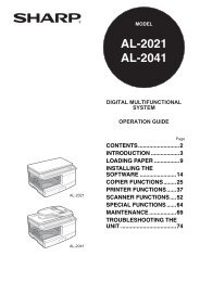
Using the Menu Screen<br />
Adjustment buttons ( / / / )<br />
MENU button<br />
Menu Selections (Adjustments)<br />
Adjustment buttons<br />
( / / / )<br />
MENU button<br />
RETURN button<br />
• Press RETURN to return<br />
to the previous screen<br />
when the menu is<br />
displayed.<br />
Example: Adjusting “Bright”.<br />
• This operation can also be performed by using the buttons on the projector.<br />
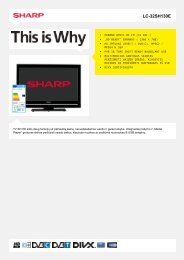
Example: “Picture” screen menu for<br />
1 Press MENU.<br />
COMPUTER (R<strong>GB</strong>) input<br />
• The menu screen is displayed.<br />
Menu item<br />
Buttons used in<br />
this operation<br />
Button used in<br />
this step<br />
2<br />
Press or and select<br />
“Picture” to adjust.<br />
Picture SIG-ADJ Video SCR-ADJ PRJ-ADJ<br />
Picture Mode<br />
Presentation<br />
Bright Boost<br />
2<br />
Bright<br />
0<br />
Contrast<br />
0<br />
Color<br />
0<br />
Tint<br />
0<br />
Sharp<br />
0<br />
Useful<br />
Features<br />
On-screen<br />
display<br />
Ex. Setting<br />
Reset<br />
MENU = END SEL./ADJ. SEL.<br />
41<br />
Info<br />
.........Indicates safeguards for using the projector.<br />
Note ....... Indicates additional information for setting up and operating the<br />
projector.<br />
For Future Reference<br />
Maintenance<br />
P. 61<br />
Troubleshooting<br />
PP. 73 to 75<br />
Index<br />
P. 79<br />
3
Contents<br />
Preparing<br />
Introduction<br />
How to Read this <strong>Operation</strong> <strong>Manual</strong> ......3<br />
Contents .................................................4<br />
IMPORTANT SAFEGUARDS ..................6<br />
How to Access the PDF <strong>Operation</strong><br />
<strong>Manual</strong>s..............................................10<br />
Accessories ..........................................11<br />
Part Names and Functions ...................13<br />
Top View ................................................ 13<br />
Front View .............................................. 13<br />
Side View (Terminals) .............................. 14<br />
Inserting the Batteries ............................. 16<br />
Usable Range ......................................... 16<br />
Easy Start<br />
Easy Start .............................................17<br />
Setup and Projection .............................. 17<br />
Setup<br />
Setting Up the Projector .......................19<br />
Video Setup............................................ 19<br />
Setting Up the Projector ......................... 19<br />
Standard Setup (Front Projection) ........... 19<br />
Projection (PRJ) Mode ............................ 20<br />
Ceiling-Mount Setup ............................... 20<br />
Connections<br />
Connecting the Projector to<br />
Other Equipment ................................21<br />
Controlling the Projector by<br />
a Computer ........................................24<br />
Attaching the Optional Lens .................26<br />
Connecting the Power Cord .................27<br />
Using<br />
Basic <strong>Operation</strong><br />
Turning the Projector On/Off ................28<br />
Turning the Projector On ......................... 28<br />
Turning the Power Off (Putting the<br />
Projector into Standby Mode) .............. 28<br />
Image Projection ..................................29<br />
Shifting the Lens ..................................... 29<br />
Using the Adjustment Feet...................... 30<br />
Adjusting the Focus ................................ 31<br />
Adjusting the Projected Image Size ......... 31<br />
Correcting Trapezoidal Distortion ............ 32<br />
Switching the Input Mode ....................... 33<br />
Adjusting the Volume .............................. 33<br />
Displaying the Black Screen and<br />
Turning Off the Sound Temporarily ....... 33<br />
Resize Mode .......................................... 34<br />
Useful Features<br />
Operating with the Remote Control......36<br />
Auto Sync (Auto Sync Adjustment) ......... 36<br />
Freezing a Moving Image ........................ 36<br />
Using the Remote Control to Operate<br />
the Computer ...................................... 37<br />
Menu Items ...........................................38<br />
Using the Menu Screen ........................41<br />
Menu Selections (Adjustments) ................41<br />
Picture Adjustment (“Picture” Menu) ....43<br />
Selecting the Picture Mode ..................... 43<br />
Adjusting the Image ................................ 44<br />
Using the Ex. Setting .............................. 44<br />
Signal Type Setting ................................. 44<br />
Adjusting the Color Temperature ............. 44<br />
Adjusting the Red/Blue ........................... 44<br />
Adjusting the Colors ............................... 45<br />
Selecting the Film Mode ......................... 45<br />
Reducing Image Noise (DNR) ................. 45<br />
Setting the Dynamic Black ...................... 45<br />
Signal Adjustment (“SIG-ADJ” Menu) ..46<br />
Adjusting the Computer Image ............... 46<br />
Setting the Resolution ............................ 46<br />
Auto Sync (Auto Sync Adjustment) ......... 46<br />
Video Adjustment (“Video” Menu) ........47<br />
Setting the Overscan .............................. 47<br />
Setting the Video System ....................... 47<br />
Setting the Video Setup .......................... 48<br />
Closed Caption ...................................... 48<br />
Adjusting the Projected Image<br />
(“SCR - ADJ” Menu) ...........................49<br />
Selecting the On-screen Display Language ... 49<br />
Selecting the Background Image ............ 49<br />
Reversing/Inverting Projected Images ..... 49<br />
Setting the Resize Mode ......................... 49<br />
Keystone Correction ............................... 50<br />
Image Resizing ....................................... 50<br />
Selecting the Wall Color .......................... 50<br />
Using the Ex. Setting .............................. 50<br />
Security Lock Function ........................... 51<br />
Keypad Lock Function ............................ 51<br />
Image Capture........................................ 51<br />
4
Adjusting the Projector Function<br />
(“PRJ - ADJ” Menu) ...........................52<br />
Detecting the Input Signals Automatically .. 52<br />
Auto Power Off Function ........................ 52<br />
Auto Restart Function ............................. 52<br />
Eco+Quiet .............................................. 52<br />
Setting the Lamp Mode .......................... 53<br />
Setting the Audio .................................... 53<br />
Using the Ex. Setting .............................. 53<br />
Fan Mode Setting ................................... 53<br />
STANDBY Mode ..................................... 53<br />
STANDBY Audio Out .............................. 53<br />
Filter Message ........................................ 54<br />
3D MODE ............................................... 54<br />
Setting the LAN/RS232C ........................ 54<br />
Setting the Network ................................ 54<br />
Returning to the Default Settings ............ 55<br />
Information ............................................. 55<br />
Viewing Stereoscopic 3D Images .........56<br />
Precautions on Viewing Stereoscopic<br />
3D Images ............................................... 56<br />
Information on the 3D Projection Function .. 58<br />
Using 3D Viewing Mode ............................. 59<br />
Appendix.................................................... 60<br />
Introduction<br />
Reference<br />
Appendix<br />
Maintenance .........................................61<br />
Cleaning and Replacing the<br />
Dust Filters .........................................62<br />
Cleaning the Dust Filters ......................... 62<br />
Replacing the Dust Filters ....................... 62<br />
Maintenance Indicators ........................64<br />
Regarding the Lamp .............................66<br />
Lamp...................................................... 66<br />
Caution Concerning the Lamp ................ 66<br />
Replacing the Lamp ............................... 66<br />
Removing and Installing the<br />
Lamp Unit ............................................ 67<br />
Resetting the Lamp Timer ...................... 68<br />
Replacing the Color Wheel ...................69<br />
Compatibility Chart ..............................71<br />
Troubleshooting ....................................73<br />
For SHARP Assistance .........................76<br />
Specifications .......................................77<br />
Dimensions ...........................................78<br />
Index .....................................................79<br />
5
6<br />
IMPORTANT SAFEGUARDS<br />
CAUTION: Please read all of these instructions before you operate this<br />
product and save these instructions for later use.<br />
Electrical energy can perform many useful functions. This product has been engineered<br />
and manufactured to assure your personal safety. BUT IMPROPER USE CAN RESULT IN<br />
POTENTIAL ELECTRICAL SHOCK OR FIRE HAZARDS. In order not to defeat the<br />
safeguards incorporated in this product, observe the following basic rules for its<br />
installation, use and servicing.<br />
1. Read Instructions<br />
All the safety and operating instructions<br />
should be read before the product is<br />
operated.<br />
2. Retain Instructions<br />
The safety and operating instructions<br />
should be retained for future reference.<br />
3. Heed Warnings<br />
All warnings on the product and in the<br />
operating instructions should be adhered to.<br />
4. Follow Instructions<br />
All operating and use instructions should<br />
be followed.<br />
5. Cleaning<br />
Unplug this product from the wall outlet before<br />
cleaning. Do not use liquid cleaners or aerosol<br />
cleaners. Use a damp cloth for cleaning.<br />
6. Attachments<br />
Do not use attachments not recommended by the<br />
product manufacturer as they may cause hazards.<br />
7. Water and Moisture<br />
Do not use this product near water–for<br />
example, near a bath tub, wash bowl, kitchen<br />
sink, or laundry tub; in a wet basement; or<br />
near a swimming pool; and the like.<br />
8. Accessories<br />
Do not place this product on an unstable<br />
cart, stand, tripod, bracket, or table. The<br />
product may fall, causing serious injury to a<br />
child or adult, and serious damage to the<br />
product. Use only with a cart, stand, tripod,<br />
bracket, or table recommended by the<br />
manufacturer, or sold with the product. Any<br />
mounting of the product should follow the<br />
manufacturer's instructions, and should use a<br />
mounting accessory recom mended by the<br />
manufacturer.<br />
9. Transportation<br />
A product and cart<br />
combination should be<br />
moved with care. Quick<br />
stops, excessive force, and<br />
uneven surfaces may<br />
cause the product and cart<br />
combination to overturn.<br />
10. Ventilation<br />
Slots and openings in the cabinet are provided<br />
for ventilation to ensure reliable operation of<br />
the product and to protect it from overheating,<br />
and these openings must not be blocked or<br />
covered. The open ings should never be<br />
blocked by placing the product on a bed, sofa,<br />
rug, or other similar surface. This prod uct<br />
should not be placed in a built-in installation<br />
such as a book case or rack unless proper<br />
ventilation is provided or the manufacturer's<br />
instruc tions have been adhered to.<br />
11. Power Sources<br />
This product should be operated only from<br />
the type of power source indicated on the<br />
marking label. If you are not sure of the<br />
type of power supply to your home, consult<br />
your product dealer or local power<br />
company. For products intended to operate<br />
from battery power, or other sources, refer<br />
to the operating instructions.<br />
12. Grounding or Polarization<br />
This product is provided with one of the<br />
following types of plugs. If the plug should<br />
fail to fi t into the power outlet, please contact<br />
your electrician.<br />
Do not defeat the safety purpose of the plug.<br />
a. Two-wire type (mains) plug.<br />
b. Three-wire grounding type (mains) plug<br />
with a grounding terminal.<br />
This plug will only fi t into a grounding<br />
type power outlet.<br />
13. Power-Cord Protection<br />
Power-supply cords should be routed so<br />
that they are not likely to be walked on or<br />
pinched by items placed upon or against<br />
them, paying particular attention to cords<br />
at plugs, convenience receptacles, and the<br />
point where they exit from the product.<br />
14. Lightning<br />
For added protection for this product during<br />
a lightning storm, or when it is left<br />
unattended and unused for long periods of<br />
time, unplug it from the wall outlet and<br />
disconnect the cable system. This will<br />
pre vent damage to the product due to<br />
lightning and power-line surges.
15. Overloading<br />
Do not overload wall outlets, extension cords,<br />
or integral convenience receptacles as this<br />
can result in a risk of fi re or electric shock.<br />
16. Object and Liquid Entry<br />
Never push objects of any kind into this<br />
product through openings as they may touch<br />
dangerous voltage points or short-out parts<br />
that could result in a fi re or electric shock.<br />
Never spill liquid of any kind on the product.<br />
17. Servicing<br />
Do not attempt to service this product<br />
yourself as opening or removing covers<br />
may expose you to dan ger ous voltage or<br />
other hazards. Refer all servicing to<br />
qualifi ed service personnel.<br />
18. Damage Requiring Service<br />
Unplug this product from the wall outlet<br />
and refer servicing to qualifi ed service<br />
personnel under the following conditions:<br />
a. When the power-supply cord or plug is<br />
damaged.<br />
b. If liquid has been spilled, or objects<br />
have fallen into the product.<br />
c. If the product has been exposed to rain<br />
or water.<br />
d. If the product does not operate normally<br />
by following the operating instructions.<br />
Adjust only those con trols that are<br />
covered by the operating instructions,<br />
as an improper adjustment of other<br />
controls may result in damage and will<br />
often require extensive work by a<br />
qualifi ed technician to restore the<br />
product to normal operation.<br />
e. If the product has been dropped or<br />
damaged in any way.<br />
f. When the product exhibits a distinct<br />
change in performance, this indicates a<br />
need for service.<br />
19. Replacement Parts<br />
When replacement parts are required, be<br />
sure the service technician has used<br />
replace ment parts specifi ed by the<br />
manufacturer or have the same<br />
characteristics as the original part.<br />
Unauthorized substitutions may result in<br />
fi re, electric shock, or other hazards.<br />
20. Safety Check<br />
Upon completion of any service or repairs<br />
to this product, ask the service technician<br />
to per form safety checks to determine that<br />
the product is in proper operating<br />
condition.<br />
21. Wall or Ceiling Mounting<br />
This product should be mounted to a wall<br />
or ceiling only as recommended by the<br />
manufacturer.<br />
22. Heat<br />
This product should be situated away from<br />
heat sources such as radiators, heat<br />
registers, stoves, or other products<br />
(including amplifi ers) that produce heat.<br />
Introduction<br />
• DLP ® and the DLP logo are registered trademarks of Texas Instruments and DLP ® Link TM<br />
is a trademark of Texas Instruments.<br />
• Microsoft ® and Windows ® are registered trademarks of Microsoft Corporation in the<br />
United States and/or other countries.<br />
• PC/AT is a registered trademark of International Business Machines Corporation in the<br />
United States.<br />
• Adobe ® Reader ® is a trademark of Adobe Systems Incorporated.<br />
• Macintosh ® is a registered trademark of Apple Computer, Inc. in the United States and/or<br />
other countries.<br />
• PJLink is a registered trademark or an application trademark in Japan, the United States,<br />
Canada, E.U., China and/or other countries/regions.<br />
• All other company or product names are trademarks or registered trademarks of their<br />
respective companies.<br />
• Some IC chips in this product include confi dential and/or trade secret property belonging<br />
to Texas Instruments. Therefore you may not copy, modify, adapt, translate, distribute,<br />
reverse engineer, reverse assemble or discompile the contents thereof.<br />
7
Observe the following safeguards when setting up your<br />
projector.<br />
8<br />
Caution concerning the lamp unit<br />
■ Potential hazard of glass particles if lamp<br />
ruptures. In case of lamp rupture, contact<br />
your nearest Sharp Authorized Projector<br />
Dealer or Service Center<br />
for replacement.<br />
See “Regarding the Lamp”<br />
on page 66.<br />
Caution concerning the setup of the<br />
projector<br />
■ For minimal servicing and to maintain high<br />
image quality, SHARP recommends that<br />
this projector be installed in an area free<br />
from humidity, dust and cigarette smoke.<br />
When the projector is subjected to these<br />
environments, the vents and lens must be<br />
cleaned more often. As long as the<br />
projector is regularly cleaned, use in these<br />
environments will not reduce the overall<br />
operation life of the unit. Internal cleaning<br />
should only be performed by a Sharp<br />
Authorized Projector Dealer or Service<br />
Center.<br />
Rest your eyes occasionally.<br />
■ Continuously watching the screen for long<br />
hours will cause eye strain. Take regular<br />
breaks to rest your eyes.<br />
Do not set up the projector in places<br />
exposed to direct sunlight or bright light.<br />
■ Position the screen so that it is not in direct<br />
sunlight or room light. Light falling directly<br />
on the screen washes out the colors,<br />
making viewing difficult. Close the curtains<br />
and dim the lights when setting up the<br />
screen in a sunny or bright room.<br />
Caution regarding placing of the projector<br />
■ Place the projector on a level site within the<br />
adjustment range (10 degrees) of the<br />
adjustment foot.<br />
■<br />
After the projector is purchased, a faint<br />
smell from the vent may appear when the<br />
power is first turned on. This is normal and<br />
is not a malfunction. It will disappear after<br />
the projector is used for a while.<br />
When using the projector in highaltitude<br />
areas such as mountains (at<br />
altitudes of approximately 1,200<br />
meters (4,000 feet) or more)<br />
■ When you use the projector in high-altitude<br />
areas with thin air, set “Fan Mode” to<br />
“High”. Neglecting this can affect the<br />
longevity of the optical system.<br />
■ Use the projector at altitudes of 3,000<br />
meters (10,000 feet) or less.<br />
Warning about placing the projector in<br />
a high position<br />
■ When placing the projector in a high<br />
position, make certain it is carefully secure<br />
to avoid personal injury caused by the<br />
projector falling down.<br />
Do not subject the projector to hard<br />
impact and/or vibration.<br />
■ Protect the lens so as not to hit or damage<br />
the surface of the lens.<br />
Avoid locations with extremes of<br />
temperature.<br />
■ The operating temperature of the projector<br />
is from 41°F to 104°F (+5°C to +40°C).<br />
■ The storage temperature of the projector is<br />
from 14°F to 140°F (–10°C to +60°C).<br />
Do not block the exhaust and intake<br />
vents.<br />
■ Allow at least 11 13 / 16 inches (30 cm) of<br />
space between the exhaust vent and the<br />
nearest wall or obstruction.<br />
■ Ensure that the intake vent and the exhaust<br />
vent are not obstructed.<br />
■ If the cooling fan becomes obstructed, a<br />
protection circuit will automatically put the<br />
projector into Standby mode to prevent<br />
overheat damage. This does not indicate a<br />
malfunction. (See pages 64 and 65.)<br />
Remove the projector power cord from the<br />
wall outlet and wait at least 10 minutes.<br />
Place the projector where the intake and<br />
exhaust vents are not blocked, plug the<br />
power cord back in and turn on the<br />
projector. This will return the projector to<br />
the normal operating condition.
Caution regarding usage of the projector<br />
■ If you are not to use the projector for a long<br />
time or before moving the projector, make<br />
certain you unplug the power cord from the<br />
wall outlet, and disconnect any other<br />
cables connected to it.<br />
■ Do not carry the projector by holding the lens.<br />
■ When storing the projector, ensure you attach<br />
the lens cap or dustproof cap to the projector.<br />
■ Do not expose the projector to direct<br />
sunlight or place next to heat sources.<br />
Doing so may affect the cabinet color or<br />
cause deformation of the plastic cover.<br />
Other connected equipment<br />
■ When connecting a computer or other audiovisual<br />
equipment to the projector, make the<br />
connections AFTER unplugging the power<br />
cord of the projector from the AC outlet and<br />
turning off the equipment to be connected.<br />
■ Please read the operation manuals of the<br />
projector and the equipment to be<br />
connected for instructions on how to make<br />
the connections.<br />
Using the projector in other countries<br />
■ The power supply voltage and the shape of<br />
the plug may vary depending on the region<br />
or country you are using the projector in.<br />
When using the projector overseas, make<br />
sure you use an appropriate power cord for<br />
the country you are in.<br />
Temperature monitor function<br />
■ If the temperature inside the projector<br />
increases, due to blockage of the air vents,<br />
or the setting location, the lamp will turn<br />
off, the cooling fan will run and then the<br />
projector will enter Standby mode, and<br />
then the TEMP. (temperature warning)/<br />
STATUS indicator will blink. Refer to<br />
“Maintenance Indicators” on pages 64 and<br />
65 for details.<br />
Info<br />
• The cooling fan regulates the internal<br />
temperature, and its performance is automatically<br />
controlled. The sound of the fan may change<br />
during projector operation due to changes in the<br />
fan speed. This does not indicate malfunction.<br />
Optional lens installation<br />
■ For installing an optional lens, refer to<br />
“Attaching the Optional Lens” on page 26<br />
or the lens installation manual (supplied<br />
with the optional lens).<br />
■ Remove the optional lens when carrying<br />
the projector. Carrying the projector with<br />
an optional lens attached can cause the<br />
projector to be damaged by vibration or<br />
other factors.<br />
■ When carrying the projector with no lens<br />
attached, attach the dustproof cap to the<br />
projector.<br />
Introduction<br />
Closed Caption uses Bitstream Vera fonts<br />
Copyright (c) 2003 by Bitstream, Inc. All Rights Reserved. Bitstream Vera is a trademark of Bitstream, Inc.<br />
Permission is hereby granted, free of charge, to any person obtaining a copy of the fonts accompanying this<br />
license (“Fonts”) and associated documentation files (the “Font Software”), to reproduce and distribute the<br />
Font Software, including without limitation the rights to use, copy, merge, publish, distribute, and/or sell<br />
copies of the Font Software, and to permit persons to whom the Font Software is furnished to do so, subject<br />
to the following conditions:<br />
The above copyright and trademark notices and this permission notice shall be included in all copies of one<br />
or more of the Font Software typefaces.<br />
The Font Software may be modifi ed, altered, or added to, and in particular the designs of glyphs or<br />
characters in the Fonts may be modifi ed and additional glyphs or characters may be added to the Fonts,<br />
only if the fonts are renamed to names not containing either the words “Bitstream” or the word “Vera”.<br />
This License becomes null and void to the extent applicable to Fonts or Font Software that has been<br />
modified and is distributed under the “Bitstream Vera” names.<br />
The Font Software may be sold as part of a larger software package but no copy of one or more of the Font<br />
Software typefaces may be sold by itself.<br />
THE FONT SOFTWARE IS PROVIDED “AS IS”, WITHOUT WARRANTY OF ANY KIND, EXPRESS OR IMPLIED,<br />
INCLUDING BUT NOT LIMITED TO ANY WARRANTIES OF MERCHANTABILITY, FITNESS FOR A PARTICULAR<br />
PURPOSE AND NONINFRINGEMENT OF COPYRIGHT, PATENT, TRADEMARK, OR OTHER RIGHT. IN NO<br />
EVENT SHALL BITSTREAM OR THE GNOME FOUNDATION BE LIABLE FOR ANY CLAIM, DAMAGES OR<br />
OTHER LIABILITY, INCLUDING ANY GENERAL, SPECIAL, INDIRECT, INCIDENTAL, OR CONSEQUENTIAL<br />
DAMAGES, WHETHER IN AN ACTION OF CONTRACT, TORT OR OTHERWISE, ARISING FROM, OUT OF THE<br />
USE OR INABILITY TO USE THE FONT SOFTWARE OR FROM OTHER DEALINGS IN THE FONT SOFTWARE.<br />
Except as contained in this notice, the names of Gnome, the Gnome Foundation, and Bitstream Inc., shall<br />
not be used in advertising or otherwise to promote the sale, use or other dealings in this Font Software<br />
without prior written authorization from the Gnome Foundation or Bitstream Inc., respectively. For further<br />
information, contact: fonts at gnome dot org.<br />
9
How to Access the PDF <strong>Operation</strong> <strong>Manual</strong>s<br />
PDF operation manuals in several languages are included in the CD-ROM. To<br />
utilize these manuals, you need to install Adobe ® Reader ® on your computer<br />
(Windows ® or Macintosh ® ).<br />
Please download Adobe ® Reader ® from the Internet (http://www.adobe.com).<br />
Accessing the PDF <strong>Manual</strong>s<br />
For Windows ® :<br />
Insert the CD-ROM in the CD-ROM drive.<br />
Double click the “My Computer” icon.<br />
Double click the “CD-ROM” drive.<br />
When you want to view the operation<br />
manual<br />
1) Double click the “MANUALS” folder.<br />
2) Double click the language (name of the<br />
folder) that you want to view.<br />
3) Double click the pdf file to access the<br />
projector manuals.<br />
When you want to view the SETUP<br />
MANUAL<br />
1) Double click the “SETUP” folder.<br />
2) Double click the language (name of the<br />
folder) that you want to view.<br />
3) Double click the pdf file to access the<br />
SETUP MANUAL.<br />
For Macintosh ® :<br />
Insert the CD-ROM in the CD-ROM drive.<br />
Double click the “CD-ROM” icon.<br />
When you want to view the operation<br />
manual<br />
1) Double click the “MANUALS” folder.<br />
2) Double click the language (name of the<br />
folder) that you want to view.<br />
3) Double click the pdf file to access the<br />
projector manuals.<br />
When you want to view the SETUP<br />
MANUAL<br />
1) Double click the “SETUP” folder.<br />
2) Double click the language (name of the<br />
folder) that you want to view.<br />
3) Double click the pdf file to access the<br />
SETUP MANUAL.<br />
Note<br />
• If the desired pdf fi le cannot be opened by double clicking the mouse, start Adobe ® Reader ® fi r st,<br />
then specify the desired fi le using the “File”, “Open” menu.<br />
SETUP MANUAL<br />
Refer to the “SETUP MANUAL” contained on the supplied CD-ROM for details.<br />
Setting up the Screen··································································· 2<br />
Screen Size and Projection Distance ··········································· 3<br />
Connecting Pin Assignments ····················································· 14<br />
RS-232C Specifi cations and Commands ··································· 16<br />
Setting up the Projector Network Environment ·························· 18<br />
Controlling the Projector via LAN ··············································· 24<br />
Operating the Projector Using the PJLink TM Protocol ·················· 27<br />
Troubleshooting ·········································································· 28<br />
Dimensions ················································································ 31<br />
10
Accessories<br />
Supplied accessories<br />
Introduction<br />
Dustproof cap<br />
<br />
Remote control<br />
<br />
Two R-6 batteries<br />
(“AAA” size, UM/SUM-4,<br />
HP-7 or similar)<br />
R<strong>GB</strong> cable<br />
(6' (1.8 m))<br />
<br />
Anti-theft screw<br />
<br />
Power cord*<br />
(1) (2) (3) (4)<br />
For U.S., Canada, etc.<br />
(6n (1.8 m))<br />
<br />
For Europe, except U.K.<br />
(6n (1.8 m))<br />
<br />
For U.K., Hong Kong<br />
and Singapore<br />
(6n (1.8 m))<br />
<br />
For Australia, New<br />
Zealand and Oceania<br />
(6n (1.8 m))<br />
<br />
* Which power cords are supplied along with your projector depends on the region. Use the power<br />
cord that corresponds to the wall outlet in your country.<br />
• <strong>Operation</strong> manuals (manual pack (including this manual and CD-ROM))<br />
For U.S., Canada and Taiwan: <br />
For Europe, Asia, Australia and New Zealand: <br />
For Korea: <br />
Note<br />
• Codes in “< >” are Replacement parts codes.<br />
• When the lens is attached, use the lens cap supplied with the lens.<br />
• You can attach the dustproof cap to the projector only when no lens is attached. (Do not attach the<br />
dustproof cap when the lens is attached.)<br />
Optional accessories<br />
■ Lamp unit<br />
■ Ceiling-mount unit<br />
■ 3 RCA to mini D-sub 15 pin cable (10 n (3.0 m))<br />
■ Six-segment color wheel<br />
AN-PH80LP<br />
AN-<strong>XG</strong>CM80 (for U.S.A only)<br />
AN-C3CP2<br />
AN-PH80CW<br />
Note<br />
• Some of the optional accessories may not be available depending on the region. Please check with<br />
your nearest Sharp Authorized Projector Dealer or Service Center.<br />
11
Accessories (Continued)<br />
Optional accessories<br />
Lens Type<br />
Projection Distance for 100" Screen Size<br />
<strong>XG</strong>-<strong>PH80W</strong>-N<br />
<strong>XG</strong>-PH80X-N<br />
Fixed wide lens (× 0.8) AN-PH808EX 5'6" (1.7 m) 5'2" (1.6 m)<br />
Wide-zoom lens (× 1.3 – 1.8) AN-PH814EZ 9'5" (2.9 m) – 12'8" (3.9 m) 8'10" (2.7 m) – 11'11" (3.6 m)<br />
Standard zoom lens (× 1.8 – 2.4) AN-PH818EZ 12'7" (3.8 m) – 16'7" (5.1 m) 11'10" (3.6 m) – 15'8" (4.8 m)<br />
Tele-zoom lens (× 2.2 – 4.4) AN-PH823EZ 15'8" (4.8 m) – 31'4" (9.5 m) 14'10" (4.5 m) – 29'6" (9.0 m)<br />
Tele-zoom lens (× 4.4 – 8.3) AN-PH845EZ 31'4" (9.5 m) – 58'8" (17.9 m) 29'6" (9.0 m) – 55'4" (16.9 m)<br />
No lens is attached to <strong>XG</strong>-<strong>PH80W</strong>-N/<strong>XG</strong>-PH80X-N. The optional lenses from Sharp are also<br />
available for specialized application. Please see your nearest Sharp Authorized Projector Dealer<br />
for details on all the lenses. (Refer to the lens operation manual when using a lens.)<br />
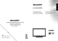
Throw Distance<br />
<strong>XG</strong>-<strong>PH80W</strong>-N<br />
The graph below is for 100-inch (254 cm) screen with 16:10 normal mode.<br />
Screen<br />
Fixed wide lens (AN-PH808EX): 5'6" (1.7 m)<br />
Throw distance ratio 1:0.8<br />
Wide-zoom lens (AN-PH814EZ): 9'5" – 12'8" (2.9 m – 3.9 m)<br />
Throw distance ratio 1:1.3–1.8<br />
Standard zoom lens (AN-PH818EZ): 12'7" – 16'7" (3.8 m – 5.1 m)<br />
Throw distance ratio 1:1.8–2.4<br />
Tele-zoom lens (AN-PH823EZ): 15'8" – 31'4" (4.8 m – 9.5 m)<br />
Throw distance ratio 1:2.2–4.4<br />
Tele-zoom lens (AN-PH845EZ): 31'4" – 58'8" (9.5 m – 17.9 m)<br />
Throw distance ratio 1:4.4–8.3<br />
5 10 15 20 25 30 35 40 45 50 55 60 (ft)<br />
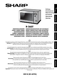
<strong>XG</strong>-PH80X-N<br />
The graph below is for 100-inch (254 cm) screen with 4:3 normal mode.<br />
Screen<br />
Fixed wide lens (AN-PH808EX): 5'2" (1.6 m)<br />
Throw distance ratio 1:0.8<br />
Wide-zoom lens (AN-PH814EZ): 8'10" – 11'11" (2.7 m – 3.6 m)<br />
Throw distance ratio 1:1.3–1.8<br />
Standard zoom lens (AN-PH818EZ): 11'10" – 15'8" (3.6 m – 4.8 m)<br />
Throw distance ratio 1:1.8–2.4<br />
Tele-zoom lens (AN-PH823EZ): 14'10" – 29'6" (4.5 m – 9.0 m)<br />
Throw distance ratio 1:2.2–4.4<br />
Tele-zoom lens (AN-PH845EZ): 29'6" – 55'4" (9.0 m – 16.9 m)<br />
Throw distance ratio 1:4.4–8.3<br />
5 10 15 20 25 30 35 40 45 50 55 60 (ft)<br />
12
Part Names and Functions<br />
Numbers in Z refer to the main pages in this operation manual where the<br />
topic is explained.<br />
15<br />
1 9<br />
2<br />
3<br />
4<br />
5<br />
6<br />
7<br />
8<br />
16 17 18 19 20<br />
16<br />
10<br />
11<br />
12<br />
13<br />
14<br />
Top View<br />
1 FOCUS buttons 31<br />
For adjusting the focus.<br />
2 H&V LENS SHIFT (P/R/O/Q) buttons 30<br />
For shifting the lens horizontally and<br />
vertically.<br />
3 MENU button 41<br />
For displaying adjustment and setting<br />
screens.<br />
4 Adjustment buttons (P/R/O/Q) 41<br />
For selecting menu items.<br />
5 ENTER button 33<br />
For setting items selected or adjusted on<br />
the menu.<br />
6 STANDBY/ON button 28<br />
For turning the power on and putting the<br />
projector into Standby mode.<br />
7 TEMP. (temperature warning)/STATUS<br />
indicator 64<br />
8 POWER indicator 64<br />
9 ZOOM buttons 31<br />
For adjusting the projected image size.<br />
10 RETURN button 41<br />
For returning to the previous menu screen<br />
during menu operations.<br />
11 INPUT button 33<br />
For switching Input mode.<br />
12 AUTO SYNC button 36<br />
For automatically adjusting images when<br />
connected to a computer.<br />
13 LAMP 1 indicator 64<br />
14 LAMP 2 indicator 64<br />
Front View<br />
Introduction<br />
Attaching the lens cap/dustproof cap<br />
Snap on the lens cap/dustproof cap straight.<br />
Removing the lens cap/dustproof cap<br />
Pull the lens cap/dustproof cap directly<br />
outward.<br />
15 Carrying handle<br />
For carrying the projector.<br />
16 Adjustment foot 30<br />
17 Remote control sensor 16<br />
18 LENS RELEASE button 26<br />
19 Dust filter 62<br />
20 Anti-theft screw 27<br />
13
Part Names and Functions (Continued)<br />
Numbers in Z refer to the main pages in this operation manual where the<br />
topic is explained.<br />
1<br />
2 3 4 5<br />
6<br />
7<br />
8<br />
9<br />
10<br />
11 12 13 11 14<br />
15<br />
16<br />
17<br />
18 19<br />
14<br />
Side View (Terminals)<br />
1 COMPUTER/COMPONENT1 input<br />
terminals 21, 23<br />
Terminal for computer R<strong>GB</strong> and component<br />
signals and audio input terminal.<br />
2 LAN terminal 25<br />
Terminal for controlling the projector using<br />
a computer via network.<br />
3 USB terminal 37<br />
Terminal connecting with the USB terminal<br />
on the computer for using the supplied<br />
remote control as the computer key board.<br />
4 DVI-D input terminals 21, 22<br />
Terminals for DVI digital R<strong>GB</strong> and digital<br />
component signals and audio input terminal.<br />
5 MONITOR OUT terminals 23<br />
• COMPUTER/COMPONENT output terminal<br />
for computer R<strong>GB</strong> and component signals.<br />
(Shared for COMPUTER/COMPONENT1<br />
and 2, COMPONENT input)<br />
• AUDIO output terminal. (Shared for all inputs)<br />
6 COMPUTER/COMPONENT2 input<br />
terminals 21, 22<br />
BNC terminals for computer R<strong>GB</strong> and<br />
component signals and audio input terminal.<br />
7 RS-232C terminal 24<br />
Terminal for controlling the projector using<br />
a computer.<br />
8 TRIGGER terminal<br />
When the projector is turned on, a control signal<br />
(DC 12V) outputs from this terminal. If an electric<br />
screen or other compatible device is connected, it<br />
can be turned on when the projector is turned on.<br />
9 Speaker 53<br />
10 Intake vent 62<br />
11 Dust filter 62<br />
12 AC socket 27<br />
Connect the supplied power cord.<br />
13 MAIN POWER switch 26<br />
Turn the projector On or Off.<br />
14 Remote control sensor 16<br />
15 Exhaust vent 62<br />
16 Kensington Security Standard connector<br />
17 COMPONENT input terminals 22<br />
Terminals for component signals and audio<br />
input terminal.<br />
18 VIDEO input terminals 23<br />
Terminal for connecting video equipment<br />
and audio input terminal.<br />
19 S-VIDEO input terminals 23<br />
Terminal for connecting video equipment<br />
with an S-video terminal and audio input<br />
terminal.<br />
Using the Kensington Lock<br />
• This projector has a Kensington Security<br />
Standard connector for use with a<br />
Kensington MicroSaver Security System.<br />
Refer to the information that came with the<br />
system for instructions on how to use it to<br />
secure the projector.
Numbers in Z refer to the main pages in this operation manual where the<br />
topic is explained.<br />
1<br />
2<br />
3<br />
4<br />
5<br />
6<br />
7<br />
8<br />
9<br />
10<br />
11<br />
12<br />
13<br />
14<br />
15<br />
16<br />
17<br />
1 STANDBY/ON button 28<br />
For turning the power on and putting the<br />
projector into Standby mode.<br />
2 KEYBOARD CURSOR (UP/DOWN/LEFT/<br />
RIGHT/ENTER) buttons 37<br />
• For moving the computer cursor when with<br />
the USB connection (using a USB cable).<br />
• Same as the [Enter] key on a computer<br />
keyboard, when with the USB connection<br />
(using a USB cable).<br />
3 PAGE UP button 37<br />
Same as the [Page Up] key on a computer<br />
keyboard, when with the USB connection<br />
(using a USB cable).<br />
4 Adjustment buttons (P/R/O/Q) 30, 41<br />
For selecting and adjusting menu items.<br />
5 ZOOM buttons 31<br />
For adjusting the projected image size.<br />
6 MENU button 41<br />
For displaying adjustment and setting<br />
screens.<br />
7 AUTO SYNC button 36<br />
For automatically adjusting images when<br />
connected to a computer.<br />
8 LENS SHIFT button 30<br />
For displaying the lens shift adjustment<br />
screen.<br />
9 3D MODE button 59<br />
For displaying the 3D MODE menu screen.<br />
10 INPUT button 33<br />
For switching Input mode.<br />
11 PAGE DOWN button 37<br />
Same as the [Page Down] key on a<br />
computer keyboard, when with the USB<br />
connection (using a USB cable).<br />
12 (ENTER) button 33<br />
For setting items selected or adjusted on<br />
the menu.<br />
13 FOCUS buttons 31<br />
For adjusting the focus.<br />
14 RETURN button 41<br />
For returning to the previous menu screen<br />
during menu operations.<br />
15 VOL +/– (Volume) buttons 33<br />
For adjusting the speaker sound level.<br />
16 AV MUTE button 33<br />
For temporarily displaying a black screen<br />
and turning off the sound.<br />
17 FREEZE button 36<br />
For freezing images.<br />
Introduction<br />
15
Part Names and Functions (Continued)<br />
Inserting the Batteries<br />
1<br />
Remove the cover by sliding towards the direction<br />
of the arrow.<br />
2<br />
3<br />
Insert the batteries.<br />
• Insert the batteries making sure the polarities correctly match the<br />
m and n marks inside the battery compartment.<br />
Replace the cover.<br />
Incorrect use of the batteries may cause them to leak or explode.<br />
Please follow the precautions below<br />
Caution<br />
• Danger of explosion if battery is incorrectly replaced.<br />
Replace only with alkaline or manganese batteries.<br />
• Insert the batteries making sure the polarities correctly match the m and n marks inside the battery<br />
compartment.<br />
• Batteries of different types have different properties, therefore do not mix batteries of different types.<br />
• Do not mix new and old batteries.<br />
This may shorten the life of new batteries or may cause old batteries to leak.<br />
• Remove the batteries from the remote control once they have run out, as leaving them in can cause them to leak.<br />
Battery fl uid from leaked batteries is harmful to skin, therefore ensure you wipe them fi rst and then<br />
remove them using a cloth.<br />
• The batteries included with this projector may run down in a short period, depending on how they are kept.<br />
Be sure to replace them as soon as possible with new batteries.<br />
• Remove the batteries from the remote control if you will not be using the remote control for a long time.<br />
• Comply with the rules (ordinance) of each local government when disposing of worn-out batteries.<br />
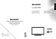
Usable Range<br />
The remote control can be used to control the<br />
projector within the ranges shown in the<br />
illustration.<br />
Remote control sensor<br />
16<br />
Note<br />
• Another remote control sensor is located<br />
on the rear of the projector. (See page 14.)<br />
• The signal from the remote control can be<br />
refl ected off a screen for easy operation.<br />
However, the effective distance of the signal<br />
may differ depending on the screen material.<br />
When using the remote control<br />
• Ensure that you do not drop it or expose it to<br />
moisture or high temperature.<br />
• The remote control may malfunction under a<br />
fl uorescent lamp. In this case, move the<br />
projector away from the fl uorescent lamp.<br />
30°<br />
23 n (7 m)<br />
30°<br />
Remote control signal<br />
transmitters<br />
Remote control
Easy Start<br />
This section shows the basic operation (projector connecting with the computer). For details,<br />
see the page described below for each step.<br />
Setup and Projection<br />
In this section, connection of the projector and the computer is explained using one example.<br />
6<br />
6<br />
5<br />
7<br />
5<br />
7<br />
8<br />
4<br />
10<br />
8<br />
4<br />
10<br />
5<br />
7<br />
8<br />
8<br />
Easy Start<br />
6<br />
7<br />
5<br />
6<br />
1. Remove the dustproof cap and then attach the optional<br />
lens P. 26<br />
2. Place the projector facing a wall or a screen P. 19<br />
3. Connect the projector to the computer and plug the power<br />
cord into the AC socket of the projector<br />
When connecting equipment other than a computer, see pages<br />
22 and 23.<br />
PP. 21, 25<br />
4. Turn the projector on<br />
Switch the MAIN POWER switch on the projector to “ON” and, after the POWER indicator<br />
has turned red, press STANDBY/ON on the projector or on the remote control.<br />
On the projector On the remote control<br />
P. 28<br />
17
Easy Start (Continued)<br />
5. Adjust the angle<br />
Adjust the projector angle:<br />
• Shift the lens horizontally and vertically.<br />
- Press H&V LENS SHIFT (P/R/O/Q) on the projector.<br />
- Press LENS SHIFT and then press P, R, O or Q on the remote<br />
control.<br />
• Adjust the projector angle by rotating the adjustment feet.<br />
P. 30<br />
6. Adjust the focus and the zoom<br />
1 Press FOCUS +/– on the projector or on the remote control to adjust the focus.<br />
2 Press ZOOM +/– on the projector or on the remote control to adjust the zoom.<br />
P. 31<br />
7. Correcting the image distortion due to the projection angle<br />
1 Press MENU to display the menu screen.<br />
2 Press O or Q to select “SCR-ADJ”.<br />
3 Press P or R to select “Keystone”.<br />
4 Press O or Q to adjust the Keystone Correction.<br />
P. 32<br />
8. Select the Input mode<br />
Press INPUT to display the INPUT list. Use P/R to select the Input mode.<br />
INPUT list<br />
INPUT<br />
DVI-D<br />
COMPUTER1<br />
COMPUTER2<br />
COMPONENT<br />
9. Turn the computer on<br />
10. Turn the power off<br />
On the projector<br />
On the remote control<br />
P. 33<br />
Press STANDBY/ON on the projector or on the remote control, and then press the button<br />
again while the confi rmation message is displayed to put the projector into Standby mode.<br />
On the projector On the remote control On-screen display<br />
Enter STANDBY Mode?<br />
Yes : Press Again<br />
No : Please Wait<br />
18<br />
• You can unplug the power cord or switch the MAIN POWER switch to “OFF” even if the<br />
projector is operating.<br />
• Even if you unplug the power cord or switch the MAIN POWER switch to “OFF”, the cooling<br />
fan continues to run for a while.<br />
P. 28
Setting Up the Projector<br />
Video Setup<br />
If using this projector outside the U.S.A., please change setting to “0 IRE” in Video Setup. (See<br />
page 48.)<br />
Setting Up the Projector<br />
For optimal image quality, position the projector perpendicular to the screen with the projector's<br />
feet flat and level. Doing so will eliminate the need for Keystone correction and provide the best<br />
image quality. (See page 32.)<br />
Standard Setup (Front Projection)<br />
■<br />
Place the projector at the required distance from the screen according to the desired picture<br />
size. (For details, refer to “SETUP MANUAL” contained on the supplied CD-ROM.)<br />
Indication of the Projection Image Size and Projection Distance<br />
<strong>XG</strong>-<strong>PH80W</strong>-N<br />
(Example: 16:10 Signal Input (Normal Mode) for the standard zoom lens (AN-PH818EZ))<br />
Picture Size<br />
500" (1270 cm)<br />
Setup<br />
200" (508 cm)<br />
100" (254 cm)<br />
80" (203 cm)<br />
60" (152cm)<br />
51"×32"<br />
68"×42"<br />
85"×53"<br />
424"×265"<br />
(1077 cm × 673 cm)<br />
170"×106"<br />
(431 cm × 269 cm)<br />
(215 cm × 135 cm)<br />
(172 cm × 108 cm)<br />
(129 cm × 81 cm)<br />
7'7"–10'0"<br />
(2.3 m – 3.0 m)<br />
10'1"–13'3"<br />
(3.1 m – 4.0 m)<br />
12'7"–16'7"<br />
(3.8 m – 5.1 m)<br />
25'2"–33'3"<br />
(7.7 m – 10.1 m)<br />
Projection<br />
Distance<br />
62'11"–83'0"<br />
(19.2 m – 25.3 m)<br />
<strong>XG</strong>-PH80X-N<br />
(Example: 4:3 Signal Input (Normal Mode) for the standard zoom lens (AN-PH818EZ))<br />
Picture Size<br />
500" (1270 cm)<br />
200" (508 cm)<br />
100" (254 cm)<br />
80" (203 cm)<br />
60" (152cm)<br />
48"×36"<br />
64"×48"<br />
80"×60"<br />
400"×300"<br />
(1016 cm × 762 cm)<br />
160"×120"<br />
(406 cm × 305cm)<br />
(203 cm × 152 cm)<br />
(163 cm × 122 cm)<br />
(122 cm × 91 cm)<br />
7'1"–9'5"<br />
(2.2 m – 2.9 m)<br />
9'6"–12'6"<br />
(2.9 m – 3.8 m)<br />
11'10"–15'8"<br />
(3.6 m – 4.8 m)<br />
23'9"–31'4"<br />
(7.2 m – 9.6 m)<br />
59'4"–78'4"<br />
(18.1 m – 23.9 m)<br />
Projection<br />
Distance<br />
19
Setting Up the Projector (Continued)<br />
Projection (PRJ) Mode<br />
The projector can use any of the 4 projection modes shown in the diagram below. Select the<br />
mode most appropriate for the projection setting in use. (You can set the PRJ mode in “SCR-<br />
ADJ” menu. See page 49.)<br />
■<br />
Table mounted, front projection<br />
[Menu item ➞ “Front”]<br />
■<br />
Ceiling mounted, front projection<br />
[Menu item ➞ “Ceiling + Front”]<br />
■<br />
Table mounted, rear projection<br />
(with a translucent screen)<br />
[Menu item ➞ “Rear”]<br />
■<br />
Ceiling mounted, rear projection<br />
(with a translucent screen)<br />
[Menu item ➞ “Ceiling + Rear”]<br />
aCeiling-Mount Setup<br />
Before mounting the projector, contact your nearest Sharp Authorized Projector Dealer or<br />
Service Center to obtain the recommended ceiling-mount adaptor and unit (sold separately).<br />
20
Connecting the Projector to Other Equipment<br />
Before connecting, ensure that the power cord of the projector is unplugged from the AC outlet<br />
and turn off the equipment to be connected. After making all connections, turn on the projector<br />
and then the other pieces of equipment. When connecting a computer, ensure that it is the last<br />
equipment to be turned on after all the connections are made.<br />
IMPORTANT: Ensure that the appropriate<br />
input mode has been selected on the<br />
projector before you turn on the connected<br />
equipment.<br />
• For more details of connection and cables, refer<br />
to the operation manual of the connected<br />
equipment.<br />
• You may need other cables or connectors not<br />
listed below.<br />
Terminals on the Projector<br />
Equipment<br />
Computer<br />
Terminal on<br />
connected equipment<br />
R<strong>GB</strong> output terminal<br />
Computer audio<br />
output terminal<br />
R<strong>GB</strong> output terminal<br />
R<strong>GB</strong> cable (supplied)<br />
Cable<br />
Computer audio cable (ø3.5 mm stereo<br />
minijack, commercially available)<br />
Mini D-sub 15 pin/5 BNC cable (commercially available)<br />
Terminal on the<br />
projector<br />
COMPUTER/<br />
COMPONENT1<br />
COMPUTER/<br />
COMPONENT2<br />
Connections<br />
Computer audio<br />
output terminal<br />
Computer audio cable (ø3.5 mm stereo<br />
minijack, commercially available)<br />
DVI digital output<br />
terminal<br />
DVI Digital cable (commercially available)<br />
DVI-D<br />
Computer audio<br />
output terminal<br />
Computer audio cable (ø3.5 mm stereo<br />
minijack, commercially available)<br />
Note<br />
• When using the ø3.5 mm mono audio cable, the volume level will be half of when using the ø3.5 mm<br />
stereo audio cable.<br />
• When connecting the projector to a compatible computer other than a PC (VGA/SVGA/<strong>XG</strong>A/S<strong>XG</strong>A/U<strong>XG</strong>A) or<br />
Macintosh (i.e. Workstation), a separate cable may be needed. Please contact your dealer for more information.<br />
• See page 71 “Compatibility Chart” for a list of computer signals compatible with the projector. Use with<br />
computer signals other than those listed may cause some of the functions to not work.<br />
• A Macintosh adaptor may be required for use with some Macintosh computers. Contact your nearest Macintosh Dealer.<br />
• Depending on the computer you are using, an image may not be projected unless the<br />
computer’s external output port is switched on (e.g. Press “Fn” and “F5” keys<br />
simultaneously when using a SHARP notebook computer). Refer to the specifi c instructions in<br />
your computer’s operation manual to enable your computer’s external output port.<br />
21
Connecting the Projector to Other Equipment (Continued)<br />
Equipment<br />
Video equipment,<br />
Camera, Video<br />
game<br />
Terminal on<br />
connected equipment<br />
DVI digital output<br />
terminal<br />
Cable<br />
DVI Digital cable (commercially available)<br />
Terminal on the<br />
projector<br />
DVI-D<br />
Audio output terminal<br />
ø3.5 mm stereo minijack to RCA audio cable<br />
(commercially available)<br />
R<strong>GB</strong> video output<br />
terminal<br />
5 BNC cable (commercially available) COMPUTER/<br />
COMPONENT2<br />
Audio output<br />
terminal<br />
ø3.5 mm stereo minijack to RCA audio cable<br />
(commercially available)<br />
Component video<br />
output terminal<br />
Component cable (commercially available) +<br />
BNC-RCA adaptor plug (commercially available)<br />
COMPUTER/<br />
COMPONENT2<br />
Audio output<br />
terminal<br />
ø3.5 mm stereo minijack to RCA audio cable<br />
(commercially available)<br />
Component video<br />
output terminal<br />
Component cable (commercially available)<br />
COMPONENT<br />
Audio output terminal<br />
RCA audio cable (commercially available)<br />
Note<br />
• When using the ø3.5 mm mono audio cable, the volume level will be half of when using the ø3.5 mm<br />
stereo audio cable.<br />
• Select the input signal type of the video equipment when connecting to the COMPUTER/<br />
COMPONENT1, 2 or DVI-D terminal. See page 44.<br />
• The HD/C sync and VD terminals may be used depending on the specifi cations of the DTV decoder<br />
connected to this projector. Please refer to the operation manual of the DTV decoder for details.<br />
• The HD/C sync terminal of the 5 BNC terminal is only for TTL signal.<br />
• Depending on specifi cations of video equipment or the DVIHDMI digital cable, the signal<br />
transmission may not work property. (The HDMI specifi cation does not support all connections to<br />
video equipment that has HDMI digital output terminal using a DVIHDMI digital cable.)<br />
• For details on compatibility for connection, see support information on DVI connection provided by<br />
the video equipment manufacturer.<br />
• When you connect video equipment with a 21-pin R<strong>GB</strong> output (Euro-scart) to the projector, use a<br />
commercially available cable that fi ts in the projector terminal you want to connect.<br />
• The projector does not support R<strong>GB</strong>C signals via the Euro-scart.<br />
22
Equipment<br />
Video equipment,<br />
Camera, Video<br />
game<br />
Terminal on<br />
connected equipment<br />
D-video output<br />
terminal<br />
Cable<br />
Cables for a camera or a video game/3 RCA to<br />
mini D-sub 15 pin cable (optional, AN-C3CP2)<br />
RCA adaptor plug (commercially available)<br />
Terminal on the<br />
projector<br />
COMPUTER/<br />
COMPONENT1<br />
Audio output terminal<br />
ø3.5 mm stereo minijack to RCA audio cable<br />
(commercially available)<br />
S-video output<br />
terminal<br />
S-video cable (commercially available)<br />
S-VIDEO<br />
Audio output<br />
terminal<br />
RCA audio cable (commercially available)<br />
Video output<br />
terminal<br />
Video cable (commercially available)<br />
VIDEO<br />
Monitor<br />
Audio output<br />
terminal<br />
R<strong>GB</strong> input<br />
terminal<br />
RCA audio cable (commercially available)<br />
R<strong>GB</strong> cable (supplied or commercially<br />
available)<br />
MONITOR OUT<br />
Connections<br />
Amplifier<br />
Audio input<br />
terminal<br />
ø3.5 mm stereo minijack to RCA audio cable<br />
(commercially available)<br />
MONITOR OUT<br />
Note<br />
• When using the ø3.5 mm mono audio cable, the volume level will be half of when using the ø3.5 mm<br />
stereo audio cable.<br />
• The audio signal is not output from the speaker of the projector when the audio cable is connected to<br />
the audio output terminal.<br />
• Video signal for monitor output is analog R<strong>GB</strong> signal as well as component signal (COMPUTER/<br />
COMPONENT1, 2). DVI input video signals would not be output.<br />
23
Controlling the Projector by a Computer<br />
When the RS-232C terminal on the projector is connected to the RS-232C serial terminal on the<br />
computer, or when the LAN terminal on the projector is connected to the LAN terminal on the<br />
computer, the computer can be used to control the projector. Refer to the “SETUP MANUAL”<br />
contained on the supplied CD-ROM for details.<br />
When connecting to a computer using an RS-232C serial control cable<br />
Computer<br />
Side view<br />
To RS-232C terminal<br />
To RS-232C terminal<br />
RS-232C serial control cable<br />
(cross type, commercially available)<br />
Note<br />
• When you establish the connection shown above, set “LAN/RS232C” in “Ex. Setting” of the “PRJ-<br />
ADJ” menu to “RS232C”.<br />
• The RS-232C function may not operate if your computer terminal is not correctly set up. Refer to the<br />
operation manual of the computer for details.<br />
• Refer to “SETUP MANUAL” contained on the supplied CD-ROM for the RS-232C<br />
specifications and commands.<br />
Info<br />
• Do not connect the RS-232C cable to a terminal other than the RS-232C terminal on the computer.<br />
This may damage your computer or projector.<br />
• Do not connect or disconnect an RS-232C serial control cable to or from the computer while it is on.<br />
This may damage your computer.<br />
24
When connecting to the LAN terminal using a LAN cable<br />
TX/RX LED (yellow)<br />
Illuminates when transmitting/receiving data.<br />
LINK LED (green)<br />
Illuminates when linked.<br />
* To ensure safety, do not connect the LAN<br />
terminal with any cables that may cause<br />
excessive voltage such as a telephone line.<br />
Hub<br />
or<br />
Computer<br />
To LAN terminal<br />
LAN cable (Category 5 type,<br />
commercially available)<br />
Note<br />
• When you establish the connection shown above, set “LAN/RS232C” in “Ex. Setting” of the “PRJ-<br />
ADJ” menu to “LAN”.<br />
• When connecting to a hub, use a straight-through Category 5 (CAT.5) type cable (commercially<br />
available).<br />
• When connecting to a computer, use a cross-over Category 5 (CAT.5) type cable (commercially<br />
available).<br />
Connections<br />
25
Attaching the Optional Lens<br />
When you attach a lens for the first time,<br />
skip steps 1 to 3. (When you replace the<br />
lens, start from step 1.)<br />
STANDBY/ON button<br />
Do not attempt to exchange the lens when the<br />
projector is installed hanging from the ceiling.<br />
Injury may occur if the lens falls.<br />
1<br />
Press STANDBY/ON on the<br />
projector or on the remote<br />
control to put the projector into<br />
standby mode.<br />
• Switch the MAIN POWER switch on the<br />
projector to “OFF”.<br />
• Disconnect the power cord and unplug the<br />
power cord from the AC socket after the<br />
cooling fan stops.<br />
MAIN POWER switch<br />
Power cord<br />
2<br />
Push the LENS RELEASE button<br />
all the way in and turn the lens<br />
anti-clockwise.<br />
• The lens will be disengaged.<br />
LENS RELEASE button<br />
Note<br />
• If the anti-theft screw is used to secure the<br />
lens, the lens cannot be removed when the<br />
LENS RELEASE button is pressed. In this<br />
case, remove the anti-theft screw fi rst.<br />
3<br />
Pull the lens out slowly.<br />
4<br />
Remove the lens cap from a<br />
replacement lens.<br />
• Start with this step when you set a lens for<br />
the fi rst time.<br />
Info<br />
• If you try to attach the lens to the projector<br />
without removing this cap, the optional lens<br />
attachment part can be damaged.<br />
26
5<br />
Insert the replacement lens with<br />
the top position mark on it facing<br />
up, and then turn the lens clockwise<br />
until you hear a click sound.<br />
• Make sure that the lens cannot be<br />
released even when you try to turn the lens<br />
anti-clockwise and pull it out.<br />
Top position mark<br />
Using the Anti-Theft Screw<br />
• The lens is secured by the above method, but<br />
for added security, an anti-theft screw is<br />
supplied to secure the lens more tightly.<br />
• The screw is designed to be rather long, and<br />
to secure the screw, give it about 40-50 turns.<br />
Connections<br />
Connecting the Power Cord<br />
Plug the supplied power cord into the AC socket on the side of the projector.<br />
Then plug into AC outlet.<br />
To AC outlet<br />
AC socket<br />
Power cord (supplied)<br />
27
Turning the Projector On/Off<br />
Turning the Projector On<br />
Note that the connections to external<br />
equipment and power outlet should be<br />
done before performing the operations<br />
written below. (See pages 21 to 25.)<br />
Remove the lens cap. Then switch the<br />
MAIN POWER switch on the projector<br />
to “ON” and, after the POWER<br />
indicator has turned red, press<br />
STANDBY/ON on the projector or on<br />
the remote control.<br />
• The POWER indicator illuminates green.<br />
• After the LAMP indicator illuminates, the projector<br />
is ready to start operation.<br />
Note<br />
• About the LAMP Indicator<br />
The LAMP indicator illuminates to indicate the<br />
status of the lamp. (See page 64 for details.)<br />
Green or orange: The lamp is on.<br />
Blinking in green or orange: The lamp is<br />
warming up.<br />
Red: The lamp is shut down abnormally<br />
or the lamp should be replaced.<br />
• When you switch on the projector, a slight<br />
fl ickering of the image may be experienced<br />
within the fi rst minute after the lamp has been<br />
illuminated. This is normal operation as the<br />
lamp's control circuitry is stabilizing the lamp<br />
output characteristics. It should not be<br />
regarded as faulty operation.<br />
• If the projector is put into Standby mode and<br />
immediately turned on again, the lamp may<br />
take some time to start projection.<br />
• When Security Lock is set, the password<br />
input box appears. To cancel the password<br />
setting, input the password that you have<br />
already set. See page 51 for details.<br />
Turning the Power Off (Putting<br />
the Projector into Standby Mode)<br />
Press STANDBY/ON on the projector or<br />
on the remote control, then press that<br />
button again while the confirmation<br />
message is displayed, to put the<br />
projector into Standby mode.<br />
• The projector cannot be turned on while cooling.<br />
Info<br />
• When “Auto Restart” is set to “On”:<br />
If the power cord is unplugged from the outlet<br />
or the breaker switch is turned off when the<br />
projector is on, then the projector<br />
automatically turns on when the power cord<br />
is plugged into the AC outlet or the breaker<br />
switch is turned on. (See page 52.)<br />
• English is the factory default language. If you<br />
want to change the on-screen display to<br />
another language, change the language<br />
according to the procedure on page 49.<br />
STANDBY/ON button<br />
LAMP 1 indicator<br />
LAMP 2 indicator<br />
POWER indicator<br />
STANDBY/ON<br />
button<br />
On-screen display (confirmation message)<br />
Enter STANDBY Mode?<br />
Yes : Press Again<br />
No : Please Wait<br />
Info<br />
Direct Power Off function:<br />
• You can unplug the power cord or switch the<br />
MAIN POWER switch to “OFF” even if the<br />
cooling fan is still running.<br />
• If you turn the power back on in the cases<br />
shown below, the lamp will take a longer<br />
time to light up than usual:<br />
– When the power cord is unplugged during<br />
operation<br />
– When the MAIN POWER switch is turned<br />
“OFF” during operation<br />
28
Image Projection<br />
Shifting the Lens<br />
In addition to the zoom function and adjustment of projection angle using the<br />
adjustment feet, you can adjust the position of the projection using the lens<br />
shift function. This is a useful function in cases such as when the screen cannot<br />
be moved.<br />
When moving upward or downward<br />
When moving in the left and right direction<br />
Adjustable<br />
range<br />
Adjustable range Adjustable range<br />
Adjustable range<br />
• The adjustable range is shown below.<br />
Horizontal range: ±10%<br />
Vertical range: +50% (AN-PH814EZ, AN-PH818EZ, AN-PH823EZ, AN-PH845EZ)/0% (AN-PH808EX)<br />
The adjustable range has limitations even within the range shown above.<br />
• The image can be adjusted as shown on the diagram.<br />
AN-PH814EZ, AN-PH818EZ, AN-PH823EZ,<br />
AN-PH845EZ<br />
Position of the image when the image is<br />
centered, both vertically and horizontally,<br />
in lens shift<br />
Shift Range<br />
AN-PH808EX<br />
Position of the image when the image is<br />
placed at the bottom vertically and is<br />
centered horizontally in lens shift<br />
Shift Range<br />
Basic<br />
<strong>Operation</strong><br />
H X 50%<br />
: Areas on which the<br />
image is masked with<br />
shadow while the lens<br />
shift function is used<br />
H<br />
Adjustable<br />
Range<br />
H<br />
Adjustable<br />
Range<br />
W<br />
W<br />
H : Height of the image<br />
W : Width of the image<br />
W X 10% W X 10%<br />
W X 10% W X 10%<br />
H : Height of the image<br />
W : Width of the image<br />
29
Image Projection (Continued)<br />
1<br />
Press H&V LENS SHIFT (P/R/O/<br />
Q) on the projector, or press<br />
LENS SHIFT and P/R/O/Q on<br />
the remote control, to adjust the<br />
image position.<br />
ROn-screen display<br />
LENS SHIFT<br />
Adjustment buttons<br />
(P/R/O/Q)<br />
LENS SHIFT button<br />
H&V LENS SHIFT<br />
(P/R/O/Q) buttons<br />
Using the Adjustment Feet<br />
• When the position of the projected image cannot be adjusted with the lens shift function, use the<br />
adjustment feet to adjust the projected angle.<br />
• The height of the projector can be adjusted using the adjustment feet when the screen is located higher<br />
than the projector, the screen is inclined or when the installation site is slightly inclined.<br />
• Install the projector so that it is as perpendicular to the screen as possible.<br />
1<br />
Rotate the adjustment feet to<br />
adjust the projected angle.<br />
• The projector is adjustable up to<br />
approximately 10 degrees.<br />
Warning!<br />
• Do not hold the lens when projector angle is<br />
adjusted.<br />
• Use caution not to pinch your fi nger in the<br />
space between the adjustment foot and the<br />
projector when the projector angle is<br />
lowered.<br />
Adjustment feet<br />
Up<br />
Down<br />
Up<br />
Down<br />
30
Adjusting the Focus<br />
Press FOCUS +/– on the projector or on<br />
the remote control to adjust the focus.<br />
Info<br />
• It is recommended that the focus be adjusted<br />
after the projector has warmed up for at least<br />
30 minutes.<br />
FOCUS buttons<br />
ZOOM buttons<br />
Adjusting the Projected<br />
Image Size<br />
Press ZOOM +/– on the projector or on<br />
the remote control to adjust the<br />
projected image size.<br />
Note<br />
• For fi ne adjustments, when H&V LENS<br />
SHIFT, FOCUS or ZOOM is pressed, the<br />
projected image moves a small amount in the<br />
desired direction for approximately one<br />
second. Hold down the buttons to move the<br />
projected image quickly.<br />
FOCUS buttons<br />
ZOOM buttons<br />
Basic<br />
<strong>Operation</strong><br />
31
Image Projection (Continued)<br />
Correcting Trapezoidal Distortion<br />
When the image is projected either from the top or from the bottom towards the<br />
screen at an angle, the image becomes distorted trapezoidally. The function for<br />
correcting trapezoidal distortion is called Keystone Correction.<br />
Note<br />
Adjustment buttons<br />
(P/R/O/Q)<br />
MENU button<br />
• The Keystone Correction can be adjusted up<br />
to an angle of approximately ±30 degrees and<br />
the screen can also be set up to an angle of<br />
approximately ±30 degrees.<br />
On-screen display<br />
(Keystone Correction mode)<br />
Keystone 0<br />
Shrinks upper side.<br />
(Move the slide bar in the + direction.)<br />
1<br />
2<br />
3<br />
4<br />
5<br />
Press MENU to display the menu<br />
screen, and then press O or Q to<br />
select “SCR-ADJ”.<br />
Press P or R to select<br />
“Keystone”.<br />
Press O or Q to adjust the<br />
Keystone Correction.<br />
Press R to select “Image<br />
Resizing”.<br />
• Only when “Keystone” is set to the values<br />
other than “0”, “Image Resizing” works.<br />
Press O or Q to correct the<br />
image distortion.<br />
Shrinks lower side.<br />
(Move the slide bar in the - direction.)<br />
On-screen display<br />
(Image Resizing mode)<br />
Image Resizing 0<br />
Shrinks the image vertically.<br />
(Move the slide bar in the + direction.)<br />
6<br />
Press MENU.<br />
• The menu screen will disappear.<br />
Info<br />
• While adjusting the image using Keystone<br />
Correction, straight lines and the edges of the<br />
image may appear jagged.<br />
Enlarges the image vertically.<br />
(Move the slide bar in the - direction.)<br />
32
INPUT button<br />
(ENTER) button<br />
P/R buttons<br />
Adjusting the Volume<br />
Press VOL +/– on the remote control<br />
to adjust the volume.<br />
On-screen display<br />
Volume 1<br />
Switching the Input Mode<br />
Select the appropriate Input mode for the<br />
connected equipment.<br />
Press INPUT on the projector or on<br />
the remote control to display the<br />
INPUT list.<br />
INPUT list<br />
INPUT<br />
DVI-D<br />
COMPUTER1<br />
COMPUTER2<br />
COMPONENT<br />
S-VIDEO<br />
VIDEO<br />
VOL +/– (Volume)<br />
buttons<br />
AV MUTE button<br />
• While the INPUT list is displayed, follow the<br />
procedure below to switch the input mode.<br />
– Press P/R to select the desired input mode<br />
and then press (ENTER).<br />
• If (ENTER) is not pressed, the projector<br />
switches to the selected input mode in a<br />
few seconds.<br />
Note<br />
• When no signal or non-supported signal is<br />
received, “NO SIGNAL” will be displayed.<br />
Note<br />
• Pressing VOL– will lower the volume.<br />
• Pressing VOL+ will raise the volume.<br />
• When the projector is connected to external<br />
equipment, the volume level of the external<br />
equipment changes in accordance with the<br />
volume level of the projector. Set the projector's<br />
volume to the lowest level when turning the<br />
projector on/off or when changing the input<br />
signal.<br />
• When you do not want to output the sound<br />
from the projector's speaker while the<br />
projector is connected to external equipment,<br />
set “Speaker” in “Audio” of the “PRJ-ADJ”<br />
menu to “Off”. (See page 53.)<br />
• The audio signal is not output from the internal<br />
speaker when connecting the audio cable to<br />
the MONITOR OUT (AUDIO) terminal.<br />
Displaying the Black Screen<br />
and Turning Off the Sound<br />
Temporarily<br />
Press AV MUTE on the remote control<br />
to temporarily display a black screen<br />
and turn off the sound.<br />
On-screen display<br />
AV MUTE<br />
Note<br />
• Pressing AV MUTE again will turn the<br />
projected image back on.<br />
Basic<br />
<strong>Operation</strong><br />
33
Image Projection (Continued)<br />
Resize Mode<br />
This function allows you to modify or<br />
customize the Resize mode to enhance<br />
the input image. You can set the Resize<br />
mode in “SCR-ADJ” menu. See page<br />
49.VID<br />
1<br />
Press MENU to display the menu<br />
screen, and then press O or Q to<br />
select “SCR-ADJ”.<br />
Adjustment buttons<br />
(P/R/O/Q)<br />
(ENTER) button<br />
MENU button<br />
2<br />
Press P or R to select “Resize”.<br />
Note<br />
3 Press O or Q to adjust the<br />
• The RESIZE function that can be selected<br />
desired Resize mode and then varies depending on the input signal<br />
press (ENTER).<br />
(resolution and vertical frequency).<br />
Resize Mode<br />
Normal<br />
RESIZE<br />
Output screen image<br />
The image is displayed with the original aspect ratio.<br />
Full<br />
The image is displayed at full-screen.<br />
16:9 An image compressed from a 16:9 aspect ratio to a 4:3 aspect ratio<br />
is restored to a 16:9 aspect ratio and displayed at full-screen.<br />
34
Basic<br />
<strong>Operation</strong><br />
RESIZE<br />
Output screen image<br />
4:3 An image stretched from a 4:3 aspect ratio to a 16:9 aspect ratio is<br />
restored to a 4:3 aspect ratio.<br />
Native<br />
The image is displayed according to the original input signal.<br />
“Native” cannot be selected when the input mode is VIDEO or<br />
S-VIDEO.<br />
About Copyrights<br />
• When using the Resize function to select an image size with a different aspect ratio to a TV<br />
program or video image, the image will look different from its original appearance. Keep this<br />
in mind while choosing an image size.<br />
• The use of the Resize or Keystone Correction function to compress or stretch the image for<br />
commercial purposes/public displays in a café, hotel, etc. may be an infringement of<br />
copyright protected by law for copyright holders. Please use caution.<br />
35
Operating with the Remote Control<br />
Auto Sync<br />
(Auto Sync Adjustment)<br />
Auto Sync function works when detecting<br />
input signal after the projector turns on.<br />
Press AUTO SYNC to manually adjust<br />
with Auto Sync function.<br />
Note<br />
• When the optimum image cannot be achieved<br />
with Auto Sync adjustment, use manual<br />
adjustments. (See page 46.)<br />
Freezing a Moving Image<br />
1<br />
Press FREEZE.<br />
• The projected image is frozen.<br />
AUTO SYNC button<br />
FREEZE button<br />
2<br />
Press FREEZE again to return to<br />
the moving image from the<br />
currently connected device.<br />
36
Using the Remote Control to Operate the Computer<br />
When connecting the projector and the computer with a USB cable, you can use the<br />
remote control to operate the computer.<br />
Connecting with a USB cable<br />
Computer<br />
To USB terminal<br />
To USB terminal<br />
USB cable<br />
(commercially available or available as<br />
Sharp service part QCNWGA014WJPZ)<br />
The computer can be operated<br />
in the following way after it is<br />
connected.<br />
■ When moving the cursor<br />
Same as the [ s/ /r /s ] keys on a<br />
computer keyboard.<br />
Press KEYBOARD CURSOR (UP/DOWN/<br />
LEFT/RIGHT).<br />
■<br />
■<br />
s<br />
When using [Enter]<br />
Same as the [Enter] key on a computer<br />
keyboard.<br />
Press KEYBOARD CURSOR (ENTER).<br />
When using [Page Up] or [Page Down]<br />
Same as the [Page Up] and [Page Down] keys<br />
on a computer keyboard.<br />
Press PAGE UP or PAGE DOWN.<br />
Note<br />
• This function only works with the Microsoft ®<br />
Windows ® OS and Mac OS ® that support<br />
USB.<br />
• Confi rm that the computer recognizes the<br />
USB connection.<br />
KEYBOARD CURSOR<br />
(ENTER) button<br />
KEYBOARD CURSOR<br />
(UP/DOWN/LEFT/RIGHT)<br />
buttons<br />
PAGE DOWN button<br />
PAGE UP button<br />
Useful<br />
Features<br />
37
Menu Items<br />
The following shows the items that can be set in the projector.<br />
“Picture” menu<br />
Main menu<br />
Picture<br />
Picture Mode<br />
Page 43 Page 43<br />
Sub menu<br />
Presentation<br />
Standard<br />
Game<br />
Movie<br />
sR<strong>GB</strong><br />
Bright Boost<br />
0<br />
2<br />
Bright<br />
Contrast<br />
Color<br />
Tint<br />
-30<br />
-30<br />
-30<br />
-30<br />
+30<br />
+30<br />
+30<br />
+30<br />
Sharp<br />
-30<br />
Page 44<br />
+30<br />
Ex. Setting<br />
Page 44<br />
Signal Type<br />
Page 44<br />
Auto<br />
R<strong>GB</strong><br />
YCbCr<br />
YPbPr<br />
CLR Temp -1<br />
Page 44<br />
Red -30<br />
Blue -30<br />
Page 44<br />
1<br />
+30<br />
+30<br />
C.M.S.<br />
Page 45<br />
Film Mode<br />
Page 45<br />
DNR<br />
Page 45<br />
Auto<br />
Off<br />
Off<br />
Level 1<br />
Level 2<br />
Level 3<br />
Reset<br />
Dynamic Black [On/Off]<br />
Page 45<br />
R<br />
Hue<br />
-30<br />
+30<br />
G<br />
Saturation<br />
-30<br />
+30<br />
B<br />
Value<br />
-30<br />
+30<br />
C<br />
M<br />
Y<br />
38
Useful<br />
Features<br />
“Signal adjustment (SIG-ADJ)” menu<br />
“Screen adjustment (SCR-ADJ)” menu<br />
Main menu<br />
Sub menu<br />
Main menu<br />
Sub menu<br />
SIG-ADJ<br />
Page 46<br />
H-Pos<br />
V-Pos<br />
Phase<br />
Clock<br />
Reset<br />
-150<br />
-60<br />
-30<br />
-150<br />
Page 46<br />
Resolution<br />
Page 46<br />
Auto Sync [On/Off]<br />
Page 46<br />
+150<br />
+60<br />
+30<br />
+150<br />
Auto<br />
Wide<br />
4:3<br />
SCR - ADJ<br />
Page 49<br />
Language<br />
Page 49<br />
Background<br />
Page 49<br />
PRJ Mode<br />
Page 49<br />
English<br />
Deutsch polski<br />
Español magyar nyelv<br />
Nederlands Türkçe<br />
Français<br />
Italiano<br />
Svenska<br />
Português<br />
Logo<br />
Custom<br />
Blue<br />
None<br />
Front<br />
Rear<br />
Ceiling + Front<br />
Ceiling + Rear<br />
Resize<br />
Page 49<br />
Normal<br />
Full<br />
4:3<br />
16:9<br />
Native<br />
“Video” menu<br />
Main menu<br />
Video<br />
Overscan [On/Off]<br />
Page 47 Page 47<br />
Video System<br />
Page 47<br />
Auto<br />
PAL<br />
SECAM<br />
NTSC4.43<br />
NTSC3.58<br />
PAL-M<br />
PAL-N<br />
PAL-60<br />
Sub menu<br />
Keystone<br />
-80<br />
Page 50<br />
Page 50<br />
Wall Color<br />
Page 50<br />
+80<br />
Image Resizing -30 +30<br />
Ex. Setting<br />
Page 50<br />
Whiteboard<br />
Blackboard<br />
Off<br />
Security Lock<br />
[Enable/Disable]<br />
Page 51<br />
Keypad Lock<br />
Page 51<br />
Video Setup<br />
Page 48<br />
Closed Caption<br />
Page 48<br />
0 IRE<br />
7.5 IRE<br />
CC1<br />
Off<br />
Image Capture<br />
Save Image<br />
Delete<br />
Page 51<br />
39
Menu Items (Continued)<br />
“Projector adjustment (PRJ-ADJ)” menu<br />
Main menu<br />
PRJ - ADJ<br />
Page 52<br />
Auto Search [On/Off]<br />
Page 52<br />
Auto Power Off [On/Off]<br />
Page 52<br />
Auto Restart [On/Off]<br />
Page 52<br />
Eco + Quiet [On/Off]<br />
Page 52<br />
Lamp Mode<br />
Page 53<br />
Sub menu<br />
Both Lamps<br />
Lamp1 Only<br />
Lamp2 Only<br />
Equal Use<br />
Audio<br />
Page 53<br />
Ex. Setting<br />
Page 53<br />
Volume 0 60<br />
Speaker [On/Off]<br />
Fan Mode<br />
Page 53<br />
STANDBY Mode<br />
Page 53<br />
STANDBY Audio Out [On/Off]<br />
Page 53<br />
Filter Message<br />
Page 54<br />
3D MODE<br />
Page 54<br />
LAN/RS232C<br />
Page 54<br />
Network<br />
Page 54<br />
Normal<br />
High<br />
Standard<br />
Eco<br />
Off<br />
100H<br />
200H<br />
500H<br />
1000H<br />
DLP ® Link TM [On/Off]<br />
Page 59<br />
DLP ® Link TM Invert<br />
Page 59<br />
LAN<br />
RS232C<br />
Link<br />
DHCP Client [On/Off]<br />
IP Address<br />
Subnet Mask<br />
Gateway<br />
DNS<br />
Reset<br />
Page 55<br />
Information<br />
Page 55<br />
All Reset<br />
Page 55<br />
Filter Timer Reset<br />
Page 55<br />
INPUT<br />
Signal Info<br />
Lamp Timer (Life)<br />
Lamp1<br />
Lamp2<br />
Filter Timer<br />
Model Name<br />
Software Version<br />
40
Using the Menu Screen<br />
Adjustment buttons (P/R/O/Q)<br />
MENU button<br />
Adjustment buttons<br />
(P/R/O/Q)<br />
MENU button<br />
RETURN button<br />
• Press RETURN to return<br />
to the previous screen<br />
when the menu is<br />
displayed.<br />
Menu Selections (Adjustments)<br />
Example: Adjusting “Bright”.<br />
• This operation can also be performed by using the buttons on the projector.<br />
1<br />
Press MENU.<br />
• The menu screen is displayed.<br />
Example: “Picture” screen menu for<br />
COMPUTER (R<strong>GB</strong>) input<br />
Menu item<br />
2<br />
Press Q or O and select<br />
“Picture” to adjust.<br />
Picture SIG-ADJ Video SCR-ADJ PRJ-ADJ<br />
Picture Mode<br />
Bright Boost<br />
Bright<br />
Contrast<br />
Color<br />
Tint<br />
Sharp<br />
Ex. Setting<br />
Reset<br />
Presentation<br />
2<br />
0<br />
0<br />
0<br />
0<br />
0<br />
MENU = END SEL./ADJ. SEL.<br />
Useful<br />
Features<br />
41
Using the Menu Screen (Continued)<br />
3 Picture<br />
SIG-ADJ Video SCR-ADJ PRJ-ADJ<br />
Press P or R and select “Bright”<br />
to adjust.<br />
• The selected item is highlighted.<br />
Picture Mode<br />
Presentation<br />
Bright Boost<br />
2<br />
Bright<br />
0<br />
Contrast<br />
0<br />
Color<br />
0<br />
Tint<br />
0<br />
Sharp<br />
0<br />
Ex. Setting<br />
Reset<br />
MENU = END SEL./ADJ. SEL.<br />
Items to be adjusted<br />
Picture SIG-ADJ<br />
Video SCR-ADJ PRJ-ADJ<br />
H-Pos<br />
V-Pos<br />
0<br />
0<br />
4 Picture<br />
SIG-ADJ Video SCR-ADJ PRJ-ADJ<br />
5<br />
Press O or Q to adjust the item<br />
selected.<br />
• The adjustment is stored.<br />
Press MENU.<br />
• The menu screen will disappear.<br />
Picture Mode<br />
Bright Boost<br />
Bright<br />
Contrast<br />
Color<br />
Tint<br />
Sharp<br />
Presentation<br />
2<br />
15<br />
0<br />
0<br />
0<br />
0<br />
Ex. Setting<br />
Reset<br />
MENU = END SEL./ADJ. SEL.<br />
42
Picture Adjustment (“Picture” Menu)<br />
Menu operation n Page 41<br />
Picture<br />
SIG-ADJ Video SCR-ADJ PRJ-ADJ Picture SIG-ADJ Video SCR-ADJ PRJ-ADJ<br />
Picture Mode<br />
Presentation<br />
Ex. Setting<br />
Bright Boost<br />
Bright<br />
Contrast<br />
Color<br />
Tint<br />
Sharp<br />
Ex. Setting<br />
Reset<br />
2<br />
0<br />
0<br />
0<br />
0<br />
0<br />
Signal Type<br />
CLR Temp<br />
Red<br />
Blue<br />
C.M.S.<br />
Film Mode<br />
DNR<br />
Dynamic Black<br />
MENU = END SEL./ADJ. SEL. MENU = END SEL./ADJ. SEL.<br />
Auto<br />
0<br />
0<br />
0<br />
Auto<br />
Level 1<br />
Off<br />
1 Selecting the Picture Mode<br />
Selectable<br />
items<br />
Presentation<br />
Description<br />
Brightens portions of image for<br />
more enhanced presentations.<br />
The default settings of each item when selecting Picture Mode<br />
CLR Temp<br />
Bright Boost<br />
0 2<br />
Standard For standard image 0 1<br />
Game Gives sharpness to the<br />
0 1<br />
projected image.<br />
Movie Gives natural tint to the<br />
–1 0<br />
projected image.<br />
sR<strong>GB</strong>* For high fi delity reproduction of<br />
images from a computer.<br />
– –<br />
• “sR<strong>GB</strong>” is displayed only when R<strong>GB</strong> signal is input.<br />
• You can set or adjust each item in the “Picture” menu to your preference. Any changes you make are<br />
retained in memory.<br />
Note<br />
• *sR<strong>GB</strong> is an international standard of color reproduction regulated by the IEC (International<br />
Electrotechnical Commission). As the fi xed color area has been decided by the IEC, the images are<br />
displayed in a natural tint based on an original image, when “sR<strong>GB</strong>” is selected.<br />
You cannot set the items, “Red”, “Blue”, “CLR Temp”, “Bright Boost”, “C.M.S.”, when “sR<strong>GB</strong>” is<br />
selected.<br />
Info<br />
• When “sR<strong>GB</strong>” is selected, the projected image may become dark, but this does not indicate a<br />
malfunction.<br />
Useful<br />
Features<br />
43
Picture Adjustment (“Picture” Menu)<br />
(Continued)<br />
Menu operation n Page 41<br />
2 Adjusting the Image<br />
Adjustment<br />
items<br />
Bright Boost<br />
Bright<br />
Contrast<br />
Color* 1<br />
Tint* 1<br />
Sharp* 1<br />
O button<br />
To improve color<br />
reproduction,<br />
lower bright<br />
boost setting.<br />
For less<br />
brightness.<br />
For less<br />
contrast.<br />
For less color<br />
intensity.<br />
For making skin<br />
tones purplish.<br />
For less<br />
sharpness.<br />
*1 Not selected in the R<strong>GB</strong> input mode.<br />
Q button<br />
To increase<br />
brightness,<br />
increase bright<br />
boost setting.<br />
For more<br />
brightness.<br />
For more<br />
contrast.<br />
For more color<br />
intensity.<br />
For making skin<br />
tones greenish.<br />
For more<br />
sharpness.<br />
Note<br />
• “Bright Boost” cannot be set when “sR<strong>GB</strong>” is<br />
selected.<br />
• To reset all adjustment items, select “Reset”<br />
and press (ENTER).<br />
Using the Ex. Setting<br />
Select “Ex. Setting” and then press (ENTER)<br />
to set “Signal Type”, “CLR Temp”, “Red”,<br />
“Blue”, “C.M.S.”, “Film Mode”, “DNR” or<br />
“Dynamic Black”.<br />
Adjusting the Color<br />
Temperature<br />
Selectable<br />
items<br />
–1<br />
0<br />
1<br />
Description<br />
For lower color temperature for<br />
warmer, reddish incandescent-like<br />
images.<br />
For higher color temperature for<br />
cooler, bluish, fl uorescent-like images.<br />
Note<br />
• “CLR Temp” cannot be set when “sR<strong>GB</strong>” is<br />
selected.<br />
• Values on “CLR Temp” are only for general<br />
standard purposes.<br />
6 Adjusting the Red/Blue<br />
Adjustment<br />
items<br />
O button Q button<br />
Red For weaker red. For stronger<br />
red.<br />
Blue<br />
For weaker<br />
blue.<br />
For stronger<br />
blue.<br />
Note<br />
• “Red” and “Blue” are not adjustable/selectable<br />
when selecting “sR<strong>GB</strong>”.<br />
4 Signal Type Setting<br />
This function allows you to select the input<br />
signal for COMPUTER/COMPONENT1, 2 or<br />
COMPONENT.<br />
Selectable<br />
items<br />
Auto<br />
R<strong>GB</strong><br />
YCbCr<br />
YPbPr<br />
Description<br />
Input signals are automatically<br />
recognized as R<strong>GB</strong> or component.<br />
Set when R<strong>GB</strong> signals are received.<br />
Set when Component signals<br />
(480I/480P/576I/576P) are received.<br />
Set when Component signals<br />
(720P/1080I/1080P) are received.<br />
44
Menu operation n Page 41<br />
7 Adjusting the Colors<br />
This function adjusts each of the six main<br />
colors that comprise the color wheel, altering<br />
their “Hue”, “Saturation”, or “Value”.<br />
Selecting the Film Mode<br />
This function provides high-quality playback<br />
of images originally projected at 24 fps, such<br />
as movies on DVDs.<br />
Selectable items<br />
Hue<br />
Saturation<br />
Value<br />
Description<br />
Sets the hue of the main colors.<br />
Sets the saturation of the main<br />
colors.<br />
Sets the brightness of the main<br />
colors.<br />
Adjusting “Hue”, “Saturation”, or “Value”.<br />
1 Select “C.M.S.” in “Ex. Setting” of the “Picture”<br />
menu and then press (ENTER).<br />
2 Select “R”, “G”, “B”, “C”, “M” or “Y” and then press<br />
(ENTER).<br />
3 Press P or R to select either “Hue”, “Saturation”, or<br />
“Value”.<br />
4 Select the color to be adjusted with O or Q.<br />
Example of adjusting the “Hue”<br />
Main colors O button Q button<br />
R (Red) Closer to magenta Closer to yellow<br />
G (Green) Closer to yellow Closer to cyan<br />
B (Blue) Closer to cyan Closer to magenta<br />
C (Cyan) Closer to green Closer to blue<br />
M (Magenta) Closer to blue Closer to red<br />
Y (Yellow) Closer to red Closer to green<br />
• When “Saturation” is selected, the selected<br />
color becomes<br />
O: lighter. Q: thicker.<br />
• When “Value” is selected, the selected color<br />
becomes<br />
O: darker. Q: brighter.<br />
Note<br />
• “C.M.S.” is not selectable when “sR<strong>GB</strong>” is<br />
selected.<br />
Selectable<br />
items<br />
Auto<br />
Off<br />
Description<br />
Films are detected automatically.<br />
Films are not detected.<br />
Note<br />
• This function is available for the following<br />
signals.<br />
With COMPUTER/COMPONENT1, 2 or<br />
COMPONENT input:<br />
- 480I<br />
- 576I<br />
- 1080I<br />
With S-VIDEO or VIDEO input:<br />
- All signals<br />
9 Reducing Image Noise (DNR)<br />
Video digital noise reduction (DNR) provides<br />
high quality images with minimal dot crawl<br />
and cross color noise.<br />
Selectable<br />
items<br />
Off<br />
Level 1<br />
Level 2<br />
Level 3<br />
Description<br />
DNR does not function.<br />
Sets the DNR level for viewing a<br />
clearer picture.<br />
Note<br />
• This function is not available for some signals.<br />
0Setting the Dynamic Black<br />
Use this function to improve the black level of<br />
the projector.<br />
Useful<br />
Features<br />
Selectable<br />
items<br />
On<br />
Off<br />
Description<br />
The black level of the projector will be<br />
improved.<br />
Dynamic Black does not function.<br />
45
Signal Adjustment (“SIG-ADJ” Menu)<br />
Menu operation n Page 41<br />
Picture SIG-ADJ Video SCR-ADJ PRJ-ADJ<br />
H-Pos<br />
V-Pos<br />
Phase<br />
Clock<br />
Reset<br />
Resolution<br />
Auto Sync<br />
0<br />
0<br />
0<br />
0<br />
Auto<br />
Off<br />
MENU = END SEL./ADJ. SEL.<br />
1 Adjusting the<br />
Computer Image<br />
If the optimum image cannot be obtained with<br />
Auto Sync adjustment, use the SIG-ADJ function.<br />
Selectable<br />
items<br />
H-Pos<br />
V-Pos<br />
Phase<br />
Clock<br />
Description<br />
Centers the on-screen image by<br />
moving it to the left or right.<br />
Centers the on-screen image by<br />
moving it up or down.<br />
Adjusts horizontal noise (similar to<br />
tracking on your VCR).<br />
Adjusts vertical noise.<br />
Note<br />
• To reset all adjustment items, select “Reset”<br />
and press (ENTER).<br />
• The adjustable range of “H-Pos” (H-Position)<br />
and “V-Pos” (V-Position) may vary depending<br />
on the screen resolution of the computer.<br />
3 Auto Sync (Auto Sync<br />
Adjustment)<br />
Selectable<br />
items<br />
On<br />
Off<br />
Description<br />
Auto Sync adjustment will occur when<br />
the projector is turned on or when the<br />
input signals are switched, when<br />
connected to a computer.<br />
Auto Sync adjustment is not<br />
automatically performed.<br />
Note<br />
• Auto Sync adjustment is also performed by<br />
pressing AUTO SYNC.<br />
• The Auto Sync adjustment may take some<br />
time to complete, depending on the image of<br />
the computer connected to the projector.<br />
• When the optimum image cannot be achieved<br />
with Auto Sync adjustment, use manual<br />
adjustments.<br />
2 Setting the Resolution<br />
Selectable<br />
items<br />
Auto<br />
Description<br />
Input signal resolution is automatically<br />
recognized.<br />
Set when the Wide signal is received.<br />
Wide<br />
4:3 Set when the 4:3 signal is received.<br />
46
Video Adjustment (“Video” Menu)<br />
Menu operation n Page 41<br />
Picture SIG-ADJ Video SCR-ADJ PRJ-ADJ<br />
Overscan<br />
Video System<br />
Video Setup<br />
Closed Caption<br />
On<br />
Auto<br />
7.5 IRE<br />
Off<br />
MENU = END SEL./ADJ. SEL.<br />
1Setting the Overscan<br />
This function allows you to set the overscan area<br />
(display area).<br />
Selectable<br />
items<br />
On<br />
Off<br />
Description<br />
The input area is displayed without the<br />
screen edges.<br />
The whole input area is displayed.<br />
Note<br />
• This function is available for the following<br />
signals.<br />
With COMPUTER/COMPONENT1, 2,<br />
COMPONENT or DVI-D input:<br />
- 480P<br />
- 576P<br />
- 720P<br />
- 1080I/1080P<br />
• If noise appears at the screen edges when<br />
“Off” is selected, set the function to “On”.<br />
• Also see “About Copyrights” on page 35.<br />
2 Setting the Video System<br />
The video input system mode is factory preset<br />
to “Auto”; however, a clear picture from the<br />
connected audio-visual equipment may not be<br />
received, depending on the Video signal<br />
difference.<br />
In that case, switch the Video signal.<br />
Selectable items<br />
Auto<br />
PAL<br />
SECAM<br />
NTSC4.43*<br />
NTSC3.58<br />
PAL-M<br />
PAL-N<br />
PAL-60<br />
* When reproducing NTSC signals in PAL<br />
video equipment.<br />
Note<br />
• The Video signal can only be set in S-VIDEO<br />
or VIDEO mode.<br />
• When “Video System” is set to “Auto”, you<br />
may not receive a clear picture due to signal<br />
differences. Should this occur, switch to the<br />
video system of the source signal.<br />
Useful<br />
Features<br />
47
Video Adjustment (“Video” Menu)<br />
(Continued)<br />
Menu operation n Page 41<br />
3 Setting the Video Setup<br />
Selectable<br />
items<br />
Description<br />
0 IRE Sets the black level to 0 IRE.<br />
7.5 IRE Sets the black level to 7.5 IRE.<br />
Note<br />
• This function is available for the following<br />
signals.<br />
With COMPUTER/COMPONENT1, 2 or<br />
COMPONENT input:<br />
- 480I<br />
With S-VIDEO or VIDEO input:<br />
- NTSC3.58<br />
Note<br />
• Closed Caption may malfunction (white blocks,<br />
strange characters, etc.) if signal conditions are<br />
poor or if there are problems at the broadcast<br />
source. This does not necessarily indicate a<br />
problem with the projector.<br />
• If any button is pressed to call up the onscreen<br />
display while viewing a Closed Caption<br />
broadcast, the closed captions will disappear.<br />
4 Closed Caption<br />
<br />
Info<br />
• This function is available for NTSC3.58 signal.<br />
• This function is available in the following cases<br />
only:<br />
Resize mode Keystone Correction<br />
Normal<br />
Full<br />
-40 − +40<br />
4:3<br />
16:9 -12 − +12<br />
• “Closed Caption” is a system which allows<br />
conversations, narration, and sound effects in TV<br />
programs (Limited regions) and home videos to<br />
be viewed as captions on the screen.<br />
• Not all programs and videos will offer closed<br />
captioning. Please look for the symbol to<br />
ensure that captions will be shown.<br />
Selectable<br />
items<br />
Description<br />
CC1<br />
Closed Caption mode for CH1 data<br />
Off —<br />
48
Adjusting the Projected Image (“SCR-ADJ” Menu)<br />
Menu operation n Page 41<br />
Picture SIG-ADJ Video SCR-ADJ PRJ-ADJ<br />
Picture SIG-ADJ Video SCR-ADJ PRJ-ADJ<br />
Language<br />
Background<br />
PRJ Mode<br />
Resize<br />
Keystone<br />
Image Resizing<br />
Wall Color<br />
Ex. Setting<br />
English<br />
Logo<br />
Front<br />
Normal<br />
0<br />
0<br />
Off<br />
Security Lock<br />
Keypad Lock<br />
Image Capture<br />
Ex. Setting<br />
Disable<br />
MENU = END SEL./ADJ. SEL. MENU = END SEL./ADJ. SEL.<br />
1 Selecting the On-screen<br />
Display Language<br />
The projector can switch the on-screen<br />
display language among 15 languages.<br />
English<br />
Deutsch<br />
Español<br />
Nederlands<br />
Français<br />
Italiano<br />
Svenska<br />
Português<br />
polski<br />
magyar nyelv<br />
Türkçe<br />
2 Selecting the Background<br />
Image<br />
Selectable items<br />
Logo<br />
Custom<br />
Blue<br />
None<br />
Description<br />
Sharp logo screen<br />
User customized image<br />
(e.g. company logo)<br />
Blue screen<br />
Black screen<br />
Note<br />
• When “Custom” is selected, an image saved<br />
using “Image Capture” can be displayed as a<br />
background image.<br />
3 Reversing/Inverting<br />
Projected Images<br />
Selectable items<br />
Front<br />
Rear<br />
Ceiling + Front<br />
Ceiling + Rear<br />
Description<br />
Normal image (Projected from<br />
the front of the screen)<br />
Reversed image (Projected from<br />
the rear of the screen or with a<br />
mirror)<br />
Inverted image (Projected from<br />
the front of the screen with an<br />
inverted projector)<br />
Reversed and inverted image<br />
(Projected with a mirror)<br />
See page 20 for details of Projection (PRJ) Mode.<br />
4 Setting the Resize Mode<br />
Use this function to stretch the image<br />
vertically or horizontally or when the edges of<br />
the image cannot be seen.<br />
Note<br />
• For details of the Resize mode, see pages<br />
34 and 35.<br />
Useful<br />
Features<br />
49
Adjusting the Projected Image (“SCR-ADJ” Menu)<br />
(Continued)<br />
Menu operation n Page 41<br />
5 Keystone Correction<br />
When the image is projected either from the top<br />
or from the bottom towards the screen at an<br />
angle, the image becomes distorted trapezoidally.<br />
The function for correcting trapezoidal distortion<br />
is called Keystone Correction.<br />
Select “Keystone” on the “SCR-ADJ”<br />
menu and adjust with the slide bar.<br />
See page 32 for details of “Correcting<br />
Trapezoidal Distortion”.<br />
Q button<br />
O button<br />
7 Selecting the Wall Color<br />
This function allows you to project the image<br />
to a colored (white or dark green) surface or<br />
wall without using a screen.<br />
Selectable items<br />
Whiteboard<br />
Blackboard<br />
Off<br />
Description<br />
Projects images onto a<br />
whiteboard.<br />
Projects images onto a<br />
blackboard (dark green).<br />
The Wall Color function is not<br />
activated.<br />
Using the Ex. Setting<br />
Select “Ex. Setting” and then press (ENTER)<br />
to set “Security Lock”, “Keypad Lock” or<br />
“Image Capture”.<br />
Note<br />
• The Keystone Correction can be adjusted up<br />
to an angle of approximately ±30 degrees.<br />
6 Image Resizing<br />
For correcting the image distortion which<br />
cannot be corrected with “Keystone”.<br />
Only when “Keystone” is set to the values<br />
other than “0”, “Image Resizing” can be<br />
adjusted.<br />
Select “Image Resizing” on the “SCR-<br />
ADJ” menu and adjust with the slide<br />
bar.<br />
See page 32 for details of “Correcting<br />
Trapezoidal Distortion”.<br />
Q button<br />
O button<br />
50
Menu operation n Page 41<br />
9 Security Lock Function<br />
This function prevents unauthorized use of the<br />
projector. Once this function is activated,<br />
users must enter the correct password each<br />
time the projector is turned on. We suggest<br />
you record the password in a safe place<br />
where only authorized users have access.<br />
Info<br />
• If you lose or forget your password, contact<br />
your nearest Sharp Authorized Projector<br />
Dealer or Service Center (see page 76). Even<br />
if the product warranty is valid, the password<br />
reset will incur a charge.<br />
■ Setting a Password<br />
1 Select “Security Lock”, then<br />
press Q when “Disable” is<br />
displayed.<br />
• The screen for entering the password<br />
appears.<br />
2<br />
3<br />
4<br />
Press a/b/c /Q (Adjustment<br />
buttons) on the remote control or on<br />
the projector to enter the password<br />
in “Setting the Password”.<br />
Password<br />
Setting the Password<br />
Confirm Password<br />
Enter the same password in<br />
“Confirm Password”.<br />
Press RETURN to exit .<br />
Note<br />
When the Security Lock is set<br />
• When Security Lock is set, the password<br />
input screen appears after the power is turned<br />
on. When it appears, enter the right password<br />
to start projection.<br />
Input screen for password<br />
Password<br />
■ Canceling a Password<br />
Select “Security Lock”, then press Q when<br />
“Enable” is displayed.<br />
0 Keypad Lock Function<br />
Use this function to lock the operation buttons<br />
on the projector.<br />
Selectable<br />
Description<br />
items<br />
No Turns off the Keypad Lock function.<br />
Yes All buttons on the projector, except<br />
STANDBY/ON, are locked.<br />
■ Taking the Keypad Lock Off<br />
Hold down b (Adjustment button) on the<br />
projector for about 5 seconds.<br />
Info<br />
• Keypad Lock cannot be released while the<br />
projector is: displaying the “Menu” screens, in<br />
Standby mode, warming up, changing input<br />
signals or operating the Auto Sync function,<br />
in Freeze mode or on the “Security Lock”<br />
screen during warming up.<br />
Image Capture<br />
This projector allows you to capture projected<br />
images (R<strong>GB</strong> signals) and set them as a<br />
startup image, or background image when no<br />
signals are being received.<br />
Note<br />
• Images can be captured only when they are<br />
from W<strong>XG</strong>A (1280 × 800) (<strong>XG</strong>-<strong>PH80W</strong>-N),<br />
<strong>XG</strong>A (1024 × 768) (<strong>XG</strong>-PH80X-N) non-interlace<br />
signals in COMPUTER/COMPONENT1, 2 or<br />
DVI-D mode with “Resize” set to “Normal”.<br />
• Images from equipment connected to VIDEO<br />
or S-VIDEO terminal cannot be captured.<br />
• To delete the captured image, select “Yes” in<br />
“Delete”, and then press (ENTER). (See<br />
OSD tree image on page 39.)<br />
• An image can be saved for either of the foursegment<br />
color wheel or the six-segment one,<br />
separately. Each color wheel can save one image.<br />
- When the four-segment color wheel is used,<br />
only the image saved for the four-segment<br />
color wheel is available.<br />
- When the six-segment color wheel is used,<br />
only the image saved for the six-segment<br />
color wheel is available.<br />
• Depending on the image type, it may take the<br />
projector some 2 minutes to complete the capture.<br />
• Switching input signals during performing Image<br />
Capture may result in the failure of the performance<br />
of the capture.<br />
Useful<br />
Features<br />
51
Adjusting the Projector Function (“PRJ-ADJ” Menu)<br />
Menu operation n Page 41<br />
Picture SIG-ADJ Video SCR-ADJ PRJ-ADJ<br />
Picture SIG-ADJ Video SCR-ADJ<br />
PRJ-ADJ<br />
Auto Search<br />
Off<br />
Ex. Setting<br />
Auto Power Off<br />
Auto Restart<br />
ECO + Quiet<br />
Lamp Mode<br />
Audio<br />
Ex. Setting<br />
Reset<br />
Information<br />
Off<br />
Off<br />
Off<br />
Both Lamps<br />
Fan Mode<br />
STANDBY Mode<br />
Standby Audio Out<br />
Filter Message<br />
3D MODE<br />
LAN/RS232C<br />
Network<br />
Normal<br />
Standard<br />
On<br />
500H<br />
LAN<br />
MENU = END SEL./ADJ. SEL. MENU = END SEL./ADJ. SEL.<br />
1 Detecting the Input<br />
Signals Automatically<br />
This function enables the projector to detect<br />
the received signal and to switch the Input<br />
mode automatically when the power is turned<br />
on.<br />
Selectable items<br />
Description<br />
On<br />
Automatically searches for and<br />
switches to the input mode in<br />
which signals are being<br />
received.<br />
Off<br />
Auto Search does not function.<br />
Note<br />
• While the “Auto Search” function is detecting<br />
the input signal, pressing a button on the<br />
projector or the remote control stops the “Auto<br />
Search” function. After the “Auto Search”<br />
function fi nishes completely, press the desired<br />
button.<br />
2 Auto Power Off Function<br />
3 Auto Restart Function<br />
Selectable<br />
items<br />
On<br />
Off<br />
Description<br />
If the power cord is unplugged from the<br />
outlet or the breaker switch is turned off<br />
when the projector is on, then the<br />
projector automatically turns on when<br />
the power cord is plugged into the AC<br />
outlet or the breaker switch is turned on.<br />
The projector does not turn on<br />
automatically when the power cord is<br />
plugged into the AC outlet or the<br />
breaker switch is turned on.<br />
To activate the Auto Restart function, you need to switch<br />
the MAIN POWER switch on the projector to “ON”.<br />
4 Eco+Quiet<br />
Selectable<br />
items<br />
Brightness and Power consumption<br />
On Approx. 83%<br />
Off 100%<br />
Selectable<br />
items<br />
On<br />
Off<br />
Description<br />
When no input signal is detected for<br />
more than 15 minutes, the projector will<br />
automatically enter Standby mode.<br />
The Auto Power Off function will be<br />
disabled.<br />
Note<br />
• When “Eco+Quiet” is set to “On”, the fan<br />
sound and power consumption are lower than<br />
they are when “Off” is selected. (Projection<br />
brightness decreases as shown in the chart.)<br />
52
Menu operation n Page 41<br />
5 Setting the Lamp Mode<br />
This function allows you to select the usage of<br />
the two lamps installed in the projector.<br />
Selectable items<br />
Both Lamps<br />
Lamp 1 Only<br />
Lamp 2 Only<br />
Equal Use<br />
Description<br />
Both lamps are used for greater<br />
brightness.<br />
The lamp 1 is used.<br />
When the lamp 1 burns out, the<br />
lamp 2 automatically switches in<br />
use.<br />
The lamp 2 is used.<br />
When the lamp 2 burns out, the<br />
lamp 1 automatically switches in<br />
use.<br />
The lamp whose remaining life<br />
time is the longer is used.<br />
Note<br />
• For lamp protection, this function is not<br />
available for several minutes when changing<br />
the lamp mode.<br />
6 Setting the Audio<br />
You can set the following Audio items.<br />
Selectable<br />
items<br />
Volume<br />
Description<br />
You can change the volume level.<br />
The adjustable range is 0 to 60.<br />
Speaker On The audio signal is output<br />
from the internal speaker.<br />
Off The audio signal is not output<br />
from the internal speaker.<br />
Note<br />
• The audio signal is not output from the speaker<br />
of the projector when the audio cable is<br />
connected to the audio output terminal and you<br />
cannot change the setting.<br />
Using the Ex. Setting<br />
Select “Ex. Setting” and then press (ENTER)<br />
to set “Fan Mode”, “STANDBY Mode”, “STANDBY<br />
Audio Out”, “Filter Message”, “3D MODE”, “LAN/<br />
RS232C” or “Network”.<br />
8 Fan Mode Setting<br />
This function changes the fan rotation speed.<br />
Selectable<br />
items<br />
Normal<br />
High<br />
Description<br />
Suitable for normal environments.<br />
Set when using the projector at<br />
altitudes of approximately 1,200 meters<br />
(4,000 feet) or more.<br />
When “Fan Mode” is set to “High”, the fan rotation<br />
speeds up, and the fan noise becomes louder.<br />
9 STANDBY Mode<br />
When set to “Eco”, power consumption is<br />
reduced in Standby mode.<br />
Selectable<br />
items<br />
Standard<br />
Eco<br />
Description<br />
The monitor output, LAN/RS232C and<br />
Network functions are activated even if<br />
the projector is in Standby mode.<br />
The monitor output, LAN/RS232C and<br />
Network functions are switched off in<br />
Standby mode.<br />
0 STANDBY Audio Out<br />
You can set audio output from the AUDIO<br />
OUTPUT terminal of the projector that is in<br />
Standby mode.<br />
Selectable<br />
items<br />
On<br />
Off<br />
Description<br />
The audio signal is output from the<br />
AUDIO OUTPUT terminal in Standby<br />
mode.<br />
The audio signal is not output from the<br />
AUDIO OUTPUT terminal in Standby<br />
mode.<br />
Note<br />
• When “Eco” is selected for “STANDBY Mode”,<br />
“STANDBY Audio Out” is set to “Off”<br />
automatically and you cannot change the<br />
setting.<br />
Useful<br />
Features<br />
53
Adjusting the Projector Function (“PRJ-ADJ” Menu)<br />
(Continued)<br />
Filter Message<br />
You can select the interval time to display a<br />
message for cleaning the filter.<br />
Clean The Filter.<br />
Selectable items<br />
Off<br />
100H/200H/<br />
500H/1000H<br />
3D MODE<br />
Description<br />
Not displaying the message.<br />
Select the interval time to display<br />
a message.<br />
You can set “DLP ® Link TM ” and “DLP ® Link TM<br />
Invert”. See “Using 3D Viewing Mode” on<br />
page 59 for details.<br />
Setting the LAN/RS232C<br />
You can select “LAN” or “RS232C” and<br />
selected terminal is only used.<br />
■<br />
IP Address/Subnet Mask/Gateway/<br />
DNS/Apply<br />
Selectable<br />
items<br />
IP Address<br />
Subnet<br />
Mask<br />
Gateway<br />
DNS<br />
Apply<br />
Menu operation n Page 41<br />
Description<br />
Factory default setting:<br />
192.168.150.002<br />
Enter an IP address appropriate for the<br />
network.<br />
Factory default setting:<br />
255.255.255.000<br />
Set the subnet mask to the same as<br />
that of the computer and equipment on<br />
the network.<br />
Factory default setting:<br />
000. 000. 000. 000<br />
* When not in use, set to “000. 000.<br />
000. 000”.<br />
Factory default setting:<br />
000. 000. 000. 000<br />
* When not in use, set to “000. 000.<br />
000. 000”.<br />
Apply and save the new settings.<br />
Selectable<br />
items<br />
LAN<br />
RS232C<br />
■ Link<br />
Selectable<br />
items<br />
Connected<br />
Disconnected<br />
Description<br />
The LAN function is activated.<br />
The RS-232C function is activated.<br />
Setting the Network<br />
Description<br />
Connected to the network.<br />
Disconnected from the network.<br />
Note<br />
• Confi rm the existing network's segment (IP<br />
address group) to avoid setting an IP address<br />
that duplicates the IP addresses of other<br />
network equipment or computers. If<br />
“192.168.150.002” is not used in a network<br />
with an IP address of “192.168.150.XXX”, you<br />
don't have to change the projector IP address.<br />
• For details about each setting, consult your<br />
network administrator.<br />
■ DHCP Client<br />
Connect the LAN cable before turning the<br />
projector on. If not, the DHCP Client function<br />
does not work. If the DHCP server is not<br />
available, set the IP Address, Subnet Mask,<br />
Gateway and DNS manually.<br />
Selectable<br />
items<br />
On<br />
Off<br />
Description<br />
Obtains confi guration parameters for IP<br />
Address, Subnet Mask, Gateway, and<br />
DNS automatically.<br />
Set the IP Address, Subnet Mask,<br />
Gateway, and DNS manually.<br />
54
Useful<br />
Features<br />
Returning to the Default<br />
Settings<br />
■ All Reset<br />
This function allows you to initialize the<br />
settings you have made in the projector.<br />
Note<br />
• The following items or menu cannot be<br />
initialized.<br />
- Lamp Timer (Life)<br />
- Filter Timer<br />
- Image stored using “Image Capture”<br />
■ Filter Timer Reset<br />
This function allows you to reset the filter<br />
timer.<br />
Note<br />
• Make sure to reset the fi lter timer after<br />
cleaning or changing the dust fi lter. (See page<br />
62.)<br />
Information<br />
Menu operation n Page 41<br />
You can confirm the following items.<br />
Displayed<br />
items<br />
INPUT<br />
Signal Info<br />
Lamp Timer<br />
(Life)<br />
Filter Timer<br />
Model Name<br />
Software<br />
Version<br />
Description<br />
Used input terminal is displayed.<br />
Current input signal information is<br />
displayed.<br />
Lamp usage time and the remaining<br />
lamp life (%) are displayed (Both<br />
Lamp1 and Lamp2). See “Lamp Life”<br />
below.<br />
Filter usage time is displayed.<br />
Model Name is displayed.<br />
Current software version is<br />
displayed.<br />
Lamp Life<br />
Lamp usage condition Remaining lamp life<br />
“Life” 100% 5%<br />
Operated exclusively<br />
with “Eco+Quiet”<br />
set to “On”<br />
Operated exclusively<br />
with “Eco+Quiet”<br />
set to “Off”<br />
Approx.<br />
3,000 hours<br />
Approx.<br />
2,000 hours<br />
Approx.<br />
150 hours<br />
Approx.<br />
100 hours<br />
Note<br />
• It is recommended that the lamp be changed<br />
when the remaining lamp life becomes 5%.<br />
• The lamp life may vary depending on the<br />
usage condition.<br />
55
Viewing Stereoscopic 3D Images<br />
Precautions on Viewing Stereoscopic 3D Images<br />
Before viewing stereoscopic 3D images, please read this section carefully.<br />
■<br />
■<br />
■<br />
WARNING<br />
Under normal conditions, viewing stereoscopic 3D images is safe for any duration that you<br />
would normally view your screen. However, some people may experience discomfort. The<br />
following precautions are recommended to minimize the potential for experiencing visual<br />
problems or any adverse symptoms.<br />
Take regular breaks, at least 5 to 15 minutes after every 30 to 60 minutes of stereoscopic 3D<br />
viewing.<br />
* Based on the guidelines issued by the 3D Consortium revised December 10, 2008.<br />
Maintain an appropriate distance from the screen. Viewing from too close a distance can<br />
strain your eyes. If you experience eye strain, immediately discontinue viewing.<br />
If you experience any of the following symptoms during viewing:<br />
– nausea<br />
– queasiness/dizziness<br />
– headache<br />
– blurry vision or double vision that lasts longer than few seconds<br />
Do not engage in any potentially hazardous activity (for example, driving a vehicle) until your<br />
symptoms have completely gone away. If symptoms persist, discontinue use and do not<br />
resume stereoscopic 3D viewing without discussing your symptoms with a physician.<br />
• As you get more comfortable viewing stereoscopic 3D:<br />
• Adjust the parallax on the 3D-video playback equipment. (You may not be able to adjust<br />
the parallax on some models of equipment.)<br />
• Adjust the projected image to the most comfortable viewing size by zooming.<br />
(Projecting images on the smallest or largest screen size possible may eliminate the<br />
stereoscopic effect and strain your eyes.)<br />
• Use the DLP ® Link Invert function to properly set the video for your left and right eyes.<br />
(For details on using “DLP ® Link Invert”, see the section on its operation in this operation<br />
manual.)<br />
56
Useful<br />
Features<br />
WARNING<br />
■<br />
The following people should limit stereoscopic 3D viewing:<br />
– Children under 6 years of age (to protect the eye growth process)<br />
– People with a history of photosensitivity<br />
– People with heart disease<br />
– People in poor health<br />
– People who are sleep deprived<br />
– People who are physically tired<br />
– People under the influence of drugs or alcohol<br />
■<br />
Epilepsy<br />
A small percentage of the population may experience epileptic seizures when viewing<br />
certain types of images that contain flashing patterns of light.<br />
IF YOU OR ANY MEMBER OF YOUR FAMILY HAS A HISTORY OF EPILEPSY<br />
The following people should consult a physician before viewing stereoscopic 3D images.<br />
– Anyone with a history of epilepsy, or who has a family member with a history of<br />
epilepsy<br />
– Children under 6 years of age<br />
– Anyone who has ever experienced epileptic seizures or sensory disturbances triggered<br />
by flashing light effects<br />
SOME LIGHT PATTERNS MAY INDUCE SEIZURES IN PERSONS WITH NO PRIOR<br />
HISTORY OF EPILEPSY<br />
Discontinue use if you experience any of the following symptoms while viewing<br />
stereoscopic 3D images.<br />
– Involuntary movements, eye or muscle twitching<br />
– Muscle cramps<br />
– Nausea, dizziness, or queasiness<br />
– Convulsions<br />
– Disorientation, confusion, or loss of awareness of your surroundings<br />
57
Viewing Stereoscopic 3D Images (Continued)<br />
Information on the 3D Projection Function<br />
• To display 3D images, this projector requires:<br />
WHAT YOU WILL NEED<br />
1) Source devices that support the field sequential format<br />
– For details on the supported signals, see the Compatibility Chart in this operation<br />
manual.<br />
2) 3D LCD shutter glasses that support the DLP ® Link* system<br />
– Contact your nearest Sharp Authorized Projector Dealer for purchasing details.<br />
* DLP ® Link is a trademark of Texas Instruments.<br />
• The projected image may become dark when using the 3D projection function (with “DLP ®<br />
Link ” set to “On”).<br />
• When “DLP ® Link” is set to “On”, the following functions may not work fully or may not be<br />
available at all.<br />
– Keystone<br />
– Resize<br />
– Image Resizing<br />
• 3D formats except for the field sequential method, such as ones used for Blu-ray 3D or DVD<br />
prepackaged media, are not compatible with this projector. (As of February 2011)<br />
• If the power of your left and right eyes greatly differs and you primarily use one eye for<br />
viewing the images, the images will not appear in 3D.<br />
In addition, images may be difficult to view in 3D or images may not be able to be viewed in<br />
3D depending on the individual or the content being displayed.<br />
The stereoscopic effect varies with the individual.<br />
• 3D viewing is possible within the range that the 3D LCD shutter glasses are able to receive<br />
light signals reflected by the screen. However, most 3D images are manufactured to be<br />
viewed from directly in front of the screen, so 3D viewing is recommended directly in front of<br />
the screen as much as possible.<br />
– The range for receiving signals varies depending on the 3D LCD shutter glasses. For<br />
details, see the operation manual of your 3D LCD shutter glasses.<br />
• 3D images may not be able to be played back correctly on your computer.<br />
58
Using 3D Viewing Mode<br />
Use the following procedure to project<br />
3D images.<br />
For operation of the 3D LCD shutter<br />
glasses and the 3D-video playback<br />
equipment, see the corresponding<br />
operation manual.<br />
P/Rbuttons<br />
(ENTER) button<br />
3D MODE button<br />
7<br />
Press P or R to select “DLP®<br />
Link”, and then select “On”.<br />
8 Select “DLP® Link Invert”, and<br />
then press (ENTER) to switch<br />
the mode and enable more<br />
natural 3D image viewing.<br />
9<br />
Warning!<br />
• If the projector, 3D-video playback<br />
equipment, and 3D LCD shutter<br />
glasses are not properly set, you may<br />
experience eye strain in addition to not<br />
being able to view the images in 3D.<br />
Press 3D MODE.<br />
• The 3D MODE menu will disappear.<br />
Projecting 3D images<br />
1<br />
2<br />
3<br />
4<br />
5<br />
6<br />
Turn the projector on.<br />
Turn the 3D-video playback<br />
equipment on.<br />
• Set the 3D-video playback equipment so<br />
that it outputs one of the signals listed in<br />
the Compatibility Chart in this operation<br />
manual.<br />
Switch the Input mode of the<br />
projector to enable input of 3D<br />
video signals.<br />
Operate the 3D-video playback<br />
equipment and play back the 3D<br />
content.<br />
Turn the 3D LCD shutter glasses<br />
on and place them over your eyes.<br />
Press 3D MODE on the remote<br />
control to display the 3D MODE<br />
menu.<br />
Note<br />
• If the images are not displayed in 3D, repeat<br />
steps 6 to 8.<br />
• You can also use “DLP ® Link” and “DLP ®<br />
Link Invert” on the menu screen to change<br />
the 3D setting.<br />
Ending 3D projection<br />
1<br />
2<br />
3<br />
Press 3D MODE on the remote<br />
control to display the 3D MODE<br />
menu.<br />
Press P or R to select “DLP®<br />
Link”, and then select “Off”.<br />
Press 3D MODE.<br />
• The 3D MODE menu will disappear.<br />
Note<br />
• You may not be able to enjoy the full 3D<br />
effects depending on the installation or usage<br />
environment of the projector.<br />
• When you use the 3D projection function, it is<br />
recommended that “Lamp Mode” be set to “Both<br />
Lamps” and “Eco + Quiet” be switched to “Off”.<br />
Useful<br />
Features<br />
59
Viewing Stereoscopic 3D Images (Continued)<br />
Appendix<br />
■<br />
How the 3D Projection Function (DLP Link ) Works<br />
The 3D projection function of this projector is compatible with the DLP ® Link system. To<br />
watch 3D images, you use a pair of 3D LCD shutter glasses that alternately display the<br />
projected images for the left and right eyes and are synchronized with a control (light) signal.<br />
Shutter glasses<br />
control light signal*<br />
■<br />
* The control light signal is transmitted from the lens of the projector, reflected by the screen,<br />
and received by the light reception sensor on the 3D LCD shutter glasses. Therefore, the<br />
range of 3D viewing varies depending on the specifications of the 3D LCD shutter glasses<br />
(light signal receiving sensitivity).<br />
For details, see the operation manual of your 3D LCD shutter glasses.<br />
For more information on the 3D projection function<br />
Future information on the 3D projection function will be posted on the following web site.<br />
http://www.sharp-world.com/projector/<br />
60
Maintenance<br />
Cleaning the projector<br />
■ Ensure that you have unplugged the power<br />
cord before cleaning the projector.<br />
■ The cabinet as well as the operation panel is<br />
made of plastic. Avoid using benzene or<br />
thinner, as these can damage the fi nish on<br />
the cabinet.<br />
■ Do not use volatile agents such as<br />
insecticides on the projector.<br />
Do not attach rubber or plastic items to the<br />
projector for long periods.<br />
The effects of some of the agents in the<br />
plastic may cause damage to the quality or<br />
fi nish of the projector.<br />
■ Wipe off dirt gently with a soft fl annel cloth.<br />
Using a chemical cloth (wet/dry sheet type<br />
cloth, etc.) may deform the components of<br />
the cabinet or cause cracking.<br />
■ Wiping with a hard cloth or using strong<br />
force may scratch the cabinet surface.<br />
■ When the dirt is hard to remove, soak a cloth<br />
in a mild detergent diluted with water, wring<br />
the cloth well and then wipe the projector.<br />
Strong cleaning detergents may discolor,<br />
warp or damage the coating on the projector.<br />
Make sure to test on a small, inconspicuous<br />
area on the projector before use.<br />
Cleaning the lens<br />
■ Use a commercially available blower or lens<br />
cleaning paper (for glasses and camera<br />
lenses) for cleaning the lens. Do not use any<br />
liquid type cleaning agents, as they may<br />
wear off the coating fi lm on the surface of the<br />
lens.<br />
■ As the surface of the lens can easily get<br />
damaged, be careful not to scrape or hit the<br />
lens.<br />
Mild detergent<br />
Mild detergent diluted<br />
with water<br />
Wax<br />
Thinner<br />
Appendix<br />
61
Cleaning and Replacing the Dust Filters<br />
When the message shown below is displayed, clean or replace the three dust filters<br />
and then reset the filter timer (see page 55). You must clean or replace all three dust<br />
filters at the same time to synchronize the filter timer.<br />
Clean The Filter.<br />
Cleaning the Dust Filters<br />
Use a vacuum cleaner to clean dust<br />
from the exhaust vent and the intake<br />
vent (bottom, side and rear).<br />
Info<br />
• The dust fi lters should be cleaned every 100<br />
hours of use. Clean the fi lters more often<br />
when the projector is used in a dusty or<br />
smoky location.<br />
• If you want to clean the air vents during<br />
projector operation, ensure you press<br />
STANDBY/ON on the projector or on the<br />
remote control and put the projector into<br />
Standby mode. After the cooling fan has<br />
stopped, clean the vents.<br />
Replacing the Dust Filters<br />
STANDBY/ON<br />
button<br />
Info<br />
• If the fi lters become too dirty to clean<br />
effectively, purchase new ones (Front:<br />
9NK3243073701, Side: 9NK3243073801,<br />
Rear: 9NK3243073601) from your nearest<br />
Sharp Authorized Projector Dealer or Service<br />
Center.<br />
1<br />
Press STANDBY/ON on the<br />
projector or on the remote<br />
control to put the projector into<br />
standby mode.<br />
• Switch the MAIN POWER switch on the<br />
projector to “OFF” after the cooling fan<br />
stops, and then disconnect the power<br />
cord and unplug the power cord from the<br />
AC socket.<br />
MAIN POWER switch<br />
AC socket<br />
62
2<br />
Remove the filter covers.<br />
• Remove the fi lter covers towards the<br />
direction of the arrow.<br />
Front<br />
Side<br />
Rear<br />
3<br />
Pick the dust filters up and lift<br />
them out of all the three filter<br />
covers as shown in the figures.<br />
4<br />
Place replacement dust filters<br />
and press them down firmly.<br />
5<br />
Replace the filter covers.<br />
• Insert the fi lter covers and push them<br />
gently as shown in the fi gure.<br />
Front<br />
Side<br />
Rear<br />
Appendix<br />
63
Maintenance Indicators<br />
■<br />
■<br />
The warning lights (POWER indicator, TEMP. (temperature warning)/STATUS indicator and<br />
LAMP indicator) on the projector indicate problems inside the projector.<br />
If a problem occurs, either the TEMP. (temperature warning)/STATUS indicator or the LAMP<br />
indicator will illuminate red, and the projector will enter Standby mode. After the projector<br />
has entered Standby mode, follow the procedures given below.<br />
Top View<br />
LAMP (1, 2) indicators<br />
TEMP. (temperature warning)/STATUS indicator<br />
POWER indicator<br />
About the TEMP. (temperature warning)/STATUS indicator<br />
If the temperature inside the projector increases, due to blockage of the air vents, or the setting<br />
location, the lamp will turn off, the cooling fan will run and then the projector will enter Standby<br />
mode, and then the TEMP. (temperature warning)/STATUS indicator will blink. When you fi nd the<br />
TEMP. (temperature warning)/STATUS indicator blinking, be sure to perform the measures<br />
described on page 65.<br />
About the LAMP indicator<br />
■ When the remaining lamp life becomes 5% or less, (yellow) and “Change The<br />
Lamp.(LAMP1/2)” will be displayed on the screen. When the percentage becomes 0%, it will<br />
change to (red), the lamp will automatically turn off and then the projector will<br />
automatically enter Standby mode. At this time, the lamp indicator will illuminate in red.<br />
■ If you try to turn on the projector a fourth time without replacing the lamp, the<br />
projector will not turn on.<br />
64<br />
Indicators on the Projector<br />
POWER indicator Red on Normal (Standby)<br />
Green on Normal (Power on)<br />
Orange blinks Normal (Cooling)<br />
Green blinks Normal (Warming up)<br />
LAMP indicator Green on Normal (“Eco + Quiet” is “Off”.)<br />
Orange on Normal (“Eco + Quiet” is “On”.)<br />
Green blinks The lamp is warming up. (“Eco + Quiet” is “Off”.)<br />
Orange blinks The lamp is warming up. (“Eco + Quiet” is “On”.)<br />
Red on/Red blinks The lamp is shut down abnormally or requires to be<br />
changed. (See page 65.)<br />
TEMP.<br />
Off<br />
Normal<br />
(temperature<br />
Red/Orange Abnormal. (See page 65.)<br />
warning)/STATUS<br />
blinks<br />
indicator
TEMP.<br />
(temperature<br />
warning)/<br />
STATUS<br />
indicator<br />
LAMP<br />
indicator<br />
Maintenance indicator<br />
Normal<br />
Off<br />
Green on<br />
(Green<br />
blinks<br />
when the<br />
lamp is<br />
warming<br />
up.)/<br />
Orange on<br />
(Eco)<br />
Orange<br />
blinks<br />
(When the<br />
lamp is<br />
cooling.)<br />
Abnormal<br />
Red blinks The TEMP.<br />
(temperature<br />
warning)/STATUS<br />
indicator blinks in<br />
red when the<br />
projector is on.<br />
Red blinks<br />
2 times<br />
(Repeatedly)<br />
Orange<br />
blinks<br />
Red blinks<br />
Red blinks<br />
2 times<br />
(Repeatedly)<br />
Red on<br />
Problem Cause Possible Solution<br />
The internal<br />
temperature is<br />
abnormally high.<br />
The lamp does<br />
not illuminate.<br />
Time to change<br />
the lamp.<br />
The lamp does<br />
not illuminate.<br />
Time to change<br />
the lamp.<br />
• The lamp unit cover • If the TEMP. (temperature<br />
is open.<br />
warning)/STATUS indicator<br />
blinks in red even when the<br />
lamp unit cover are<br />
securely installed, contact<br />
your nearest Sharp<br />
Authorized Projector Dealer<br />
or Service Center (see<br />
page 76) for advice.<br />
• Temperatures • Use the projector in an<br />
around the projector area with a temperature of<br />
are high.<br />
lower than 104°F (+40ºC).<br />
• Blocked air intake<br />
• Internal circuit<br />
failure.<br />
• Cooling fan<br />
breakdown<br />
• Internal circuit failure<br />
• Clogged air intake<br />
• Relocate the projector to<br />
an area with proper<br />
ventilation. (See page 8.)<br />
• Take the projector to your<br />
nearest Sharp Authorized<br />
Projector Dealer or Service<br />
Center (see page 76) for<br />
repair.<br />
• No lamp<br />
• Install the lamp unit.<br />
• Remaining lamp life • Disconnect the power cord<br />
becomes 5% or less. from the AC outlet, and<br />
then connect it again.<br />
• The lamp is shut<br />
• Carefully replace the lamp.<br />
down abnormally.<br />
(See page 66.)<br />
• Burnt-out lamp<br />
• Lamp circuit failure<br />
• The lamp life is over.<br />
• Take the projector to your<br />
nearest Sharp Authorized<br />
Projector Dealer or Service<br />
Center (see page 76) for<br />
repair.<br />
• Please exercise care when<br />
replacing the lamp.<br />
• Securely install the cover.<br />
* For information about other types of blinking, contact your nearest Sharp Authorized Projector<br />
Dealer or Service Center (see page 76).<br />
Info<br />
• If the TEMP. (temperature warning)/STATUS indicator illuminates, and the projector enters Standby<br />
mode, follow the possible solutions above and then wait until the projector has cooled down<br />
completely before plugging in the power cord and turning the power back on. (At least 10 minutes.)<br />
• If the power is turned off for a brief moment due to power outage or some other cause while using<br />
the projector, and the power supply recovers immediately after that, the LAMP indicator will<br />
illuminate in red and the lamp may not be lit. In this case, unplug the power cord from the AC outlet,<br />
replace the power cord in the AC outlet and then turn the power on again.<br />
• The cooling fan keeps the internal temperature of the projector constant and this function is<br />
controlled automatically. The sound of the cooling fan may change during operation because the fan<br />
speed may change and this is not a malfunction.<br />
Appendix<br />
65
Regarding the Lamp<br />
Lamp<br />
■<br />
■<br />
It is recommended that the lamp (sold separately) be replaced when the remaining lamp life becomes<br />
5% or less, or when you notice a signifi cant deterioration in the picture and color quality. The lamp life<br />
(percentage) can be checked with the on-screen display. (See page 55.)<br />
Purchase a replacement lamp of type AN-PH80LP from your place of purchase, nearest Sharp<br />
Authorized Projector Dealer or Service Center.<br />
IMPORTANT NOTE TO U.S. CUSTOMERS:<br />
The lamp included with this projector is backed by a 90-day parts and labor limited<br />
warranty. All service of this projector under warranty, including lamp replacement,<br />
must be obtained through a Sharp Authorized Projector Dealer or Service Center.<br />
For the name of the nearest Sharp Authorized Projector Dealer or Service Center,<br />
please call toll-free: 1-888-GO-SHARP (1-888-467-4277).<br />
Hg LAMP CONTAINS MERCURY For State Lamp Disposal<br />
Information<br />
www.lamprecycle.org or 1-800-BE-SHARP<br />
U.S.A ONLY<br />
Caution Concerning the Lamp<br />
■<br />
■<br />
■<br />
■<br />
This projector utilizes a pressurized mercury lamp. A loud sound may indicate lamp failure. Lamp failure<br />
can be attributed to numerous sources such as: excessive shock, improper cooling, surface scratches<br />
or deterioration of the lamp due to a lapse of usage time.<br />
The period of time up to failure largely varies depending on the individual lamp and/or the condition and<br />
the frequency of use. It is important to note that failure can often result in the bulb cracking.<br />
When the lamp replacement indicator and on-screen display icon are illuminated, it is recommended<br />
that the lamp be replaced with a new one immediately, even if the lamp appears to be operating<br />
normally.<br />
Should the lamp break, there is also a possibility that glass particles may spread inside of the projector.<br />
In such a case, it is recommended you contact your nearest Sharp Authorized Projector Dealer or<br />
Service Center to assure safe operation.<br />
Should the lamp break, the glass particles may spread inside the lamp cage or gas contained in the<br />
lamp may be vented into the room from the exhaust vent. Because the gas in this lamp includes<br />
mercury, ventilate the room well if the lamp breaks and avoid all exposure to the released gas. In case of<br />
exposure to the gas, consult a doctor as soon as possible.<br />
Replacing the Lamp<br />
Caution<br />
• Do not remove the lamp unit from the projector right after use. The lamp will be very hot and may cause<br />
burns or injury.<br />
• Wait at least one hour after the power cord is disconnected to allow the surface of the lamp unit to fully<br />
cool before removing the lamp unit.<br />
■ Carefully change the lamp by following the instructions described in this section.<br />
* If you wish, you may have the lamp replaced at your nearest Sharp Authorized Projector<br />
Dealer or Service Center.<br />
* If the new lamp does not light after replacement, take your projector to the nearest Sharp Authorized Projector<br />
Dealer or Service Center for repair.<br />
66
Removing and Installing the<br />
Lamp Unit<br />
Info<br />
• Do not touch the glass surface of the lamp<br />
unit or the inside of the projector.<br />
• To avoid injury to yourself and damage to the<br />
lamp, make sure you carefully follow the<br />
steps below.<br />
• Do not loosen other screws except for the<br />
lamp unit cover and lamp unit.<br />
Optional<br />
accessory<br />
Warning!<br />
•<br />
Do not remove the lamp unit from the<br />
projector right after use. The lamp and parts<br />
around the lamp will be very hot and may<br />
cause burns or injury.<br />
Lamp unit<br />
AN-PH80LP<br />
1<br />
Press STANDBY/ON on the<br />
projector or on the remote<br />
control to put the projector into<br />
Standby mode.<br />
STANDBY/ON button<br />
2<br />
Switch the MAIN POWER switch<br />
on the projector to “OFF” and<br />
then disconnect the power cord.<br />
• Unplug the power cord from the AC<br />
socket.<br />
• Leave the lamp until it has fully cooled<br />
down (about 1 hour).<br />
MAIN POWER switch<br />
AC socket<br />
3<br />
Remove the lamp unit cover.<br />
• Loosen the user service screw (1) that<br />
secures the lamp unit cover. Remove the<br />
lamp unit cover (2).<br />
4<br />
Remove the lamp unit.<br />
• Loosen the securing screws (two for each<br />
lamp) from the lamp unit. Hold the lamp<br />
unit by the handle and pull it in the<br />
direction of the arrow. At this time, keep<br />
the lamp unit horizontal and do not tilt it.<br />
User service screw<br />
(for lamp unit cover)<br />
Appendix<br />
67
Regarding the Lamp (Continued)<br />
5<br />
6<br />
Insert the new lamp unit.<br />
• Press the lamp unit fi rmly into the lamp unit<br />
compartment. Fasten the securing screw.<br />
Replace the lamp unit cover.<br />
• Align the lamp unit cover and slide it to<br />
close (1). Then tighten the user service<br />
screw (2) to secure the lamp unit cover.<br />
Info<br />
• If the lamp unit and lamp unit cover<br />
are not correctly installed, the power<br />
will not turn on, even if the power<br />
cord is connected to the projector.<br />
Resetting the Lamp Timer<br />
Reset the lamp timer after replacing the lamp.<br />
Info<br />
• Make sure to reset the lamp timer only when<br />
replacing the lamp. If you reset the lamp timer<br />
and continue to use the same lamp, this may<br />
cause the lamp to become damaged or explode.<br />
• You can reset the lamp timer only when<br />
“STANDBY mode” is set to “Standard”.<br />
AC socket<br />
1<br />
2<br />
Connect the power cord and<br />
switch the MAIN POWER switch<br />
on the projector to “ON”.<br />
• Plug the power cord into the AC socket of<br />
the projector.<br />
Reset the lamp timer.<br />
• The projector enters Standby mode when<br />
you reset the lamp timer.<br />
For Lamp 1<br />
• When you reset the timer, press MENU →<br />
ENTER → ENTER → MENU → O →<br />
STANDBY/ON on the projector.<br />
• “LAMP1 0000H” is displayed, indicating<br />
that the lamp timer is reset.<br />
For Lamp 2<br />
• When you reset the timer, press MENU →<br />
ENTER → ENTER → MENU → Q →<br />
STANDBY/ON on the projector.<br />
• “LAMP2 0000H” is displayed, indicating<br />
that the lamp timer is reset.<br />
MENU button<br />
O/Q buttons<br />
ENTER button<br />
STANDBY/ON<br />
button<br />
68
Replacing the Color Wheel<br />
The projector is equipped with a four-segment color wheel. You can replace it with a<br />
six-segment color wheel (sold separately). The replacement procedure described<br />
below also applies when you put the four-segment color wheel back in the place of<br />
the six-segment one.<br />
Warning!<br />
• Do not remove the color wheel from the<br />
projector right after use. The lamp and parts<br />
around the lamp will be very hot and may<br />
cause burns or injury.<br />
1<br />
Press STANDBY/ON on the<br />
projector or on the remote<br />
control to put the projector into<br />
Standby mode.<br />
STANDBY/ON button<br />
2<br />
Switch the MAIN POWER switch<br />
on the projector to “OFF” and<br />
then disconnect the power cord.<br />
• Unplug the power cord from the AC<br />
socket.<br />
• Leave the lamp until it has fully cooled<br />
down (about 1 hour).<br />
MAIN POWER switch<br />
AC socket<br />
3<br />
Remove the lamp unit cover.<br />
• Loosen the user service screw (1) that<br />
secures the lamp unit cover. Remove the<br />
lamp unit cover (2).<br />
User service screw<br />
(for lamp unit cover)<br />
Appendix<br />
69
Replacing the Color Wheel (Continued)<br />
4<br />
5<br />
Loosen the 4 retaining screws<br />
from the four-segment color<br />
wheel.<br />
Hold the color wheel and pull it in<br />
the direction of the arrow.<br />
Caution<br />
The module contains components that<br />
can be damaged or destroyed by<br />
electrostatic discharge. Please pick the<br />
module with the handle.<br />
Handle<br />
6<br />
7<br />
Insert the six-segment color<br />
wheel, and tighten the 4 retaining<br />
screws.<br />
Replace the lamp unit cover.<br />
• Align the lamp unit cover and slide it to<br />
close (1). Then tighten the user service<br />
screw (2) to secure the lamp unit cover.<br />
Info<br />
Storing the Unused Color Wheel:<br />
Use the zipper bag in which the six-segment<br />
color wheel was packaged to store the<br />
unused color wheel. This bag prevents dust<br />
and dirt from collecting on the color wheel.<br />
70
Compatibility Chart<br />
Computer<br />
• Multiple signal support<br />
Horizontal Frequency: 15, 31-90 kHz,<br />
Vertical Frequency: 50-85 Hz,<br />
Pixel Clock: 12-165 MHz<br />
Sync signal: Compatible with TTL level<br />
• Compatible with sync on green signal<br />
PC/MAC Mode Resolution<br />
Horizontal<br />
Vertical Analog Digital<br />
Display<br />
Frequency (kHz) Frequency (Hz) Support Support <strong>XG</strong>-<strong>PH80W</strong>-N <strong>XG</strong>-PH80X-N<br />
31.5 60 ✔ ✔<br />
37.9 72 ✔ ✔<br />
VGA 640 × 480<br />
37.5 75 ✔ ✔<br />
43.3 85 ✔<br />
35.2 56 ✔ ✔<br />
Upscale<br />
37.9 60 ✔ ✔<br />
48.1 72 ✔ ✔<br />
SVGA 800 × 600<br />
Upscale<br />
46.9 75 ✔ ✔<br />
53.7 85 ✔<br />
48.4 60 ✔ ✔<br />
56.5 70 ✔ ✔<br />
<strong>XG</strong>A 1024 × 768<br />
TRUE<br />
60.0 75 ✔ ✔<br />
68.7 85 ✔<br />
PC<br />
1280 × 720 45.0 60 ✔ ✔<br />
1280 × 768 47.8 60 ✔ ✔<br />
TRUE<br />
49.7 60 ✔ ✔<br />
W<strong>XG</strong>A 1280 × 800<br />
62.8 75 ✔<br />
47.7 60 1360 × 768 ✔<br />
1366 × 768 47.7 60 ✔<br />
1440 × 900 55.9 60 W<strong>XG</strong>A+ ✔<br />
Intelligent<br />
Compression<br />
1152 × 864 67.5 75 ✔<br />
1280 × 960 60.0 60 ✔ ✔<br />
Intelligent<br />
S<strong>XG</strong>A<br />
64.0 60 ✔ ✔ Compression<br />
1280 × 1024<br />
80.0 75 ✔ ✔<br />
S<strong>XG</strong>A+ 1400 × 1050 65.3 60 ✔ ✔<br />
WS<strong>XG</strong>A+ 1680 × 1050 65.3 60 ✔<br />
U<strong>XG</strong>A 1600 × 1200 75.0 60 ✔<br />
VGA 640 × 480 34.9 67 ✔<br />
MAC 13”<br />
Upscale<br />
MAC 16” SVGA 832 × 624 49.7 75 ✔<br />
Upscale<br />
MAC 19” <strong>XG</strong>A 1024 × 768 60.2 75 ✔ TRUE<br />
Intelligent<br />
Intelligent<br />
MAC 21” S<strong>XG</strong>A 1152 × 870 68.7 75 ✔<br />
Compression Compression<br />
Note<br />
• Optimum image quality will be achieved by matching your computer's output resolution to the<br />
resolution that corresponds to “TRUE” in the “Display” column shown above.<br />
• When “Screen resolution” of the computer is different from the resolution displayed on the projected<br />
image, follow the procedures shown below.<br />
– Make the appropriate adjustments for “Resolution” in “SIG-ADJ”.<br />
– Depending on the computer you are using, the output signal may not be faithful to the “Screen resolution”<br />
adjustment. Check the settings of the computer's signal output. If the settings cannot be changed, it is<br />
recommended that the resolution be set to the one that corresponds to “TRUE” in the “Display” column.<br />
Appendix<br />
71
Compatibility Chart (Continued)<br />
3D Supported Signals<br />
Signal Horizontal Frequency (kHz) Vertical Frequency (Hz)<br />
Analog<br />
Digital<br />
Support<br />
Support<br />
SVGA 800 × 600<br />
37.9 60 ✔ ✔<br />
77.1 120 ✔ ✔<br />
<strong>XG</strong>A 1024 × 768<br />
48.4 60 ✔ ✔<br />
98.6 120 ✔ ✔<br />
W<strong>XG</strong>A<br />
1280 × 800<br />
49.7 60 ✔ ✔<br />
101.6 120 * 1 ✔ ✔<br />
1280 × 720<br />
45.0 60 ✔ ✔<br />
92.6 120 ✔ ✔<br />
*1 Reduced Blanking<br />
Note<br />
• Your computer graphics card must be able to display 3D stereoscopic signals.<br />
Please check with your computer/graphic card specifi cations or call your computer manufacturer to<br />
ensure this capability.<br />
DTV<br />
Signal<br />
Horizontal<br />
Frequency (kHz)<br />
Vertical<br />
Frequency (Hz)<br />
Analog<br />
Support<br />
Digital<br />
Support<br />
Signal<br />
Horizontal<br />
Frequency (kHz)<br />
Vertical<br />
Frequency (Hz)<br />
Analog<br />
Support<br />
480I 15.7 60 ✔ 1080I 28.1 50 ✔ ✔<br />
480P 31.5 60 ✔ ✔ 1080I 33.8 60 ✔ ✔<br />
576I 15.6 50 ✔ 1080P 56.3 50 ✔ ✔<br />
576P 31.3 50 ✔ ✔ 1080P 67.5 60 ✔ ✔<br />
720P 37.5 50 ✔ ✔<br />
720P 45.0 60 ✔ ✔<br />
Digital<br />
Support<br />
72
Troubleshooting<br />
Problem Check Page<br />
• Projector power cord is not plugged into the wall outlet.<br />
27<br />
• Power to the external connected devices is off.<br />
–<br />
• The selected Input mode is wrong.<br />
33<br />
• The AV Mute function is working.<br />
33<br />
• Cables are incorrectly connected to the projector.<br />
21–25<br />
• Remote control battery has run out.<br />
16<br />
No picture and no sound • External output has not been set when connecting notebook computer. 21<br />
or projector does not<br />
start.<br />
• When the connected DVI digital equipment is turned on before the<br />
“DVI-D” input mode is selected on the projector, the image may not be<br />
projected properly or may not be displayed at all. Ensure that the<br />
appropriate input mode has been selected and set the input signal type<br />
on the projector before you turn on the connected equipment.<br />
• The lamp unit cover is not installed correctly.<br />
67, 68<br />
• Cables are incorrectly connected to the projector.<br />
21–25<br />
• “Bright” is set to minimum position.<br />
44<br />
• Depending on the computer you are using, an image may not be –<br />
projected unless the signal output setting of the computer is switched<br />
to the external output. Refer to the computer's operation manual for<br />
how to switch its signal output settings.<br />
• Is “On” selected in “DLP ® Link TM ”?<br />
58<br />
Sound is heard but no<br />
picture appears<br />
(or picture is dark).<br />
Dark or bluish image • Check that “Wall Color” is confi gured correctly.<br />
50<br />
• Image adjustments are incorrectly set.<br />
44<br />
(S-VIDEO, VIDEO Input only)<br />
• Video input system is incorrectly set.<br />
47<br />
(COMPUTER/COMPONENT1, 2, COMPONENT, DVI Input only)<br />
• Input signal type (R<strong>GB</strong>/Component) is incorrectly set.<br />
44<br />
Color is faded or poor.<br />
Picture is blurred;<br />
noise appears.<br />
• Adjust the focus.<br />
31<br />
• The projection distance exceeds the focus range.<br />
–<br />
• When an optional lens is attached, refer to the operation manual of the<br />
lens.<br />
• There is fog on the lens. If the projector is carried from a cold room into a –<br />
warm room, or if it is suddenly heated, condensation may form on the surface<br />
of the lens and the image will become blurred. Set up the projector at least<br />
one hour before it is to be used. If condensation should form, remove the<br />
power cord from the wall outlet and wait for it to clear.<br />
(Computer Input only)<br />
• Perform “SIG-ADJ” Adjustments (“Clock” and “Phase” Adjustment) 46<br />
• Turn off the LCD display of the notebook computer.<br />
• Noise may appear depending on the computer.<br />
–<br />
• Cables are incorrectly connected to the projector.<br />
21–25<br />
• Volume is set to minimum.<br />
33<br />
• When the projector is connected to an external device and the volume<br />
is set to minimum, the sound is not output even if you turn up the<br />
volume of the external device.<br />
Picture appears but no<br />
sound is heard.<br />
• “Speaker” is set to “Off”.<br />
• The AV Mute function is working.<br />
53<br />
33<br />
Appendix<br />
73
Troubleshooting (Continued)<br />
Problem Check Page<br />
Data image is not • Make the necessary adjustments of each item in the “SIG-ADJ” menu. 46<br />
centered. • Depending on the computer you are using, the output resolution signal –<br />
may be different from the one you have set. For details, refer to the<br />
operation manual of the computer.<br />
An unusual sound is • If the picture is normal, the sound is due to cabinet shrinkage caused –<br />
occasionally heard from by room temperature changes. This will not affect operation or<br />
the cabinet. performance.<br />
Maintenance indicator on<br />
the projector illuminates<br />
or blinks in red.<br />
Picture is green on<br />
COMPUTER/<br />
COMPONENT1, 2<br />
(Component).<br />
Picture is pink<br />
(no green) on<br />
COMPUTER/<br />
COMPONENT1, 2 or<br />
DVI (R<strong>GB</strong>).<br />
Picture is too bright and<br />
whitish.<br />
The cooling fan becomes<br />
noisy.<br />
The lamp does not light<br />
up even after the<br />
projector turns on.<br />
The lamp suddenly turns<br />
off during projection.<br />
The image sometimes<br />
fl i c ke r s.<br />
The lamp needs much<br />
time to turn on.<br />
Picture is dark.<br />
The remote control<br />
cannot be used.<br />
• See “Maintenance Indicators”.<br />
64<br />
• Change the input signal type setting.<br />
44<br />
• Image adjustments are incorrectly set.<br />
44<br />
• When temperature inside the projector increases, the cooling fan runs 8, 9,<br />
faster.<br />
64, 65<br />
• The LAMP indicator is illuminating in red.<br />
64, 67, 68<br />
Replace the lamp.<br />
• Cables are incorrectly connected to the projector or the connected 21–25<br />
equipment works improperly.<br />
• If this happens frequently, replace the lamp.<br />
67<br />
• The lamp will eventually need to be changed.<br />
67<br />
While the remaining lamp life draws to a close, replace the lamp.<br />
• Operate the remote control while pointing it at the projector's remote 16<br />
control sensor.<br />
• The remote control may be too far away from the projector.<br />
• If direct sunlight or a strong fl uorescent lamp is shining on the<br />
projector's remote control sensor, place the projector where it will not<br />
be affected by strong light.<br />
• The batteries may be depleted or inserted incorrectly. Make sure the 16<br />
batteries are inserted correctly or insert new ones.<br />
74
Problem Check Page<br />
3D images fl icker when • Images may appear to fl icker when fl uorescent light or ambient light –<br />
watching in a room. enters your vision.<br />
– Turn off the lights.<br />
– Block any ambient light.<br />
Ghosting (a double image) • Check that you are using 3D LCD shutter glasses that support the –<br />
occurs without the image DLP ® Link system.<br />
appearing in 3D. – Be sure to use 3D LCD shutter glasses that support the DLP ® Link<br />
system.<br />
• Check that the shutters on the 3D LCD shutter glasses are working –<br />
properly.<br />
– Turn the 3D LCD shutter glasses off and then on again.<br />
– Check the batteries of the 3D LCD shutter glasses.<br />
– Check that the 3D LCD shutter glasses are set to 3D viewing mode.<br />
Some 3D LCD shutter glasses are equipped with a special viewing<br />
mode (such as “dual view mode”) in addition to the normal 3D<br />
viewing mode. See the operation manual of your 3D LCD shutter<br />
glasses.<br />
• Check the settings of the projector.<br />
–<br />
– Turn the DLP ® Link function “On”.<br />
– Use “DLP ® Link Invert” to change the setting.<br />
• Check whether a signal that is not supported is being input.<br />
72<br />
– Confi gure your 3D application at the correct resolution and refresh<br />
rate.<br />
Make sure you are running your 3D application in resolutions that<br />
support 3D. To support 3D, your 3D application must be confi gured<br />
to run at the correct settings for this projector.<br />
For details on the supported signals, see “3D Supported Signals” of<br />
the Compatibility Chart.<br />
• If the projector is connected to a computer for 3D image playback, –<br />
check that a stereoscopically-enabled application is being used.<br />
– Use the applicable software.<br />
– Set the applicable software to the fi eld sequential format.<br />
• Check that there are no obstructions between the screen and the 3D –<br />
LCD shutter glasses.<br />
– Remove any obstructions.<br />
Any obstructions may cause the glasses not to function properly<br />
causing the lenses to fl icker or turn off. Do not place your hand or<br />
other objects in front of the 3D control signal sensor on the glasses.<br />
• Check whether there is a source of high intensity lighting nearby. –<br />
– Block the light or turn it off.<br />
High intensity lighting can interfere with communication between the<br />
3D LCD shutter glasses and the screen resulting in some fl icker.<br />
• Check whether two or more projectors are projecting 3D images at the –<br />
same time.<br />
– Use only one projector at a time.<br />
This unit is equipped with a microprocessor. Its performance could be adversely affected by incorrect<br />
operation or interference. If this should happen, unplug the Unit and plug it in again after more than 5<br />
minutes.<br />
Appendix<br />
75
For SHARP Assistance<br />
If you encounter any problems during setup or operation of this projector, first<br />
refer to the “Troubleshooting” section on pages 73 to 75. If this operation<br />
manual does not answer your question, please contact the SHARP Service<br />
departments listed below.<br />
U.S.A.<br />
Canada<br />
Mexico<br />
Sharp Electronics Corporation<br />
1-888-GO-SHARP (1-888-467-4277)<br />
lcdsupport@sharpsec.com<br />
http://www.sharpusa.com<br />
Sharp Electronics of Canada Ltd.<br />
(905) 568-7140<br />
http://www.sharp.ca<br />
Sharp Electronics Corporation<br />
Mexico Branch<br />
(525) 716-9000<br />
http://www.sharp.com.mx<br />
Latin America Sharp Electronics Corp. Latin<br />
American Group<br />
(305) 264-2277<br />
www.servicio@sharpsec.com<br />
http://www.sharpla.com<br />
Germany<br />
U.K.<br />
Sharp Electronics (Europe) GMBH<br />
01805-234675<br />
http://www.sharp.de<br />
Sharp Electronics (U.K.) Ltd.<br />
08705 274277<br />
http://www.sharp.co.uk/customersupport<br />
Benelux<br />
Australia<br />
New Zealand<br />
Singapore<br />
Hong Kong<br />
SHARP Electronics Benelux BV<br />
0900-SHARPCE (0900-7427723)<br />
Nederland<br />
9900-0159 Belgium<br />
http://www.sharp.nl<br />
http://www.sharp.be<br />
http://www.sharp.lu<br />
Sharp Corporation of Australia Pty.<br />
Ltd.<br />
1300-135-022<br />
http://www.sharp.net.au<br />
Sharp Corporation of New Zealand<br />
Phone: (09) 573-0111<br />
Fax: (09) 573-0112<br />
http://www.sharp.net.nz<br />
Sharp-Roxy Sales (S) Pte. Ltd.<br />
65-226-6556<br />
ckng@srs.global.sharp.co.jp<br />
http://www.sharp.com.sg<br />
Sharp-Roxy (HK) Ltd.<br />
(852) 2410-2623<br />
dcmktg@srh.global.sharp.co.jp<br />
http://www.sharp.com.hk<br />
Italy<br />
Sharp Electronics (Italy) S.P.A.<br />
(39) 02-89595-1<br />
http://www.sharp.it<br />
Taiwan<br />
Sharp Corporation (Taiwan)<br />
0800-025111<br />
http://www.sharp-scot.com.tw<br />
France<br />
Spain<br />
Switzerland<br />
Sweden<br />
Austria<br />
Sharp Electronics France<br />
01 49 90 35 40<br />
hotlineced@sef.sharp-eu.com<br />
http://www.sharp.fr<br />
Sharp Electronica Espana, S.A.<br />
93 5819700<br />
sharplcd@sees.sharp-eu.com<br />
http://www.sharp.es<br />
Sharp Electronics (Schweiz) AG<br />
0041 1 846 63 11<br />
cattaneo@sez.sharp-eu.com<br />
http://www.sharp.ch<br />
Sharp Electronics ( Nordic ) AB<br />
(46) 8 6343600<br />
vision.support@sen.sharp-eu.com<br />
http://www.sharp.se<br />
Sharp Electronics (Europe) GMBH<br />
Branch Office Austria<br />
0043 1 727 19 123<br />
pogats@sea.sharp-eu.com<br />
http://www.sharp.at<br />
Malaysia<br />
U.A.E.<br />
Thailand<br />
Korea<br />
India<br />
Sharp-Roxy Sales & Service Co.<br />
(60) 3-5125678<br />
Sharp Middle East Fze<br />
971-4-81-5311<br />
helpdesk@smef.global.sharp.co.jp<br />
Sharp Thebnakorn Co. Ltd.<br />
02-236-0170<br />
svc@stcl.global.sharp.co.jp<br />
http://www.sharp-th.com<br />
Sharp Electronics Incorporated of<br />
Korea<br />
(82) 2-3660-2002<br />
lcd@sharp-korea.co.kr<br />
http://www.sharpkorea.co.kr<br />
Sharp Business Systems (India)<br />
Limited<br />
(91) 11- 6431313<br />
service@sharp-oa.com<br />
76
Specifications<br />
Model <strong>XG</strong>-<strong>PH80W</strong>-N <strong>XG</strong>-PH80X-N<br />
Display devices 0.65" DLP ® Chip 0.7" DLP ® Chip<br />
Resolution W<strong>XG</strong>A (1280 × 800) <strong>XG</strong>A (1024 × 768)<br />
Optional Lens<br />
(Standard)<br />
(AN-PH818EZ)<br />
F number F 1.7 – 1.9<br />
Zoom<br />
Power, ×1.3 (f = 26.0 – 34.0 mm)<br />
Focus<br />
Power<br />
Lens shift Power (V : +50% / H : ±10%)<br />
Input terminals DVI-D (Compatible with HDCP) ×1<br />
Computer/Component (5BNC) ×1<br />
Computer/Component<br />
×1<br />
(D-sub 15 pin)<br />
Component (RCA)<br />
×1 (Y/Pb (Cb)/Pr (Cr))<br />
S-Video (mini DIN 4 pin) ×1<br />
Video (RCA) ×1<br />
Audio (ø3.5 mm stereo minijack) ×3<br />
Audio (RCA)<br />
×2 (L/R)<br />
Output<br />
terminals<br />
Control and<br />
communication<br />
terminals<br />
Computer/Component<br />
×1<br />
(D-sub 15 pin)<br />
Audio (ø3.5 mm stereo minijack) ×1 (variable audio output)<br />
TRIGGER<br />
×1 (DC 12 V output)<br />
LAN (RJ-45) ×1<br />
USB (Type B) ×1<br />
RS-232C (D-sub 9 pin) ×1<br />
3 W × 2 (Stereo)<br />
280 W × 2 lamps<br />
AC 100 – 240 V<br />
50/60 Hz<br />
7.3 A<br />
715 W (20.3 W/0.28 W) with AC 100 V<br />
675 W (21.3 W/0.41 W) with AC 240 V<br />
41°F to 104°F (+5°C to +40°C)<br />
Plastic<br />
Speaker<br />
Projection lamp<br />
Rated voltage<br />
Rated frequency<br />
Input current<br />
Power consumption (STANDBY Mode: Standard/Eco)<br />
<strong>Operation</strong> temperature<br />
Cabinet<br />
Dimensions (main body only) [W × H × D] 19 57 /64" × 7 41 /64" × 15 11 /64"<br />
(505 × 194 × 385 mm)<br />
Weight (approx.)<br />
36.4 lbs. (16.5 kg)<br />
As a part of policy of continuous improvement, SHARP reserves the right to make design and<br />
specifi cation changes for product improvement without prior notice. The performance specifi cation<br />
fi gures indicated are nominal values of production units. There may be some deviations from these<br />
values in individual units.<br />
This SHARP projector uses a DLP ® chip. This very sophisticated panel contains 1,024,000<br />
(<strong>XG</strong>-<strong>PH80W</strong>-N) or 786,432 (<strong>XG</strong>-PH80X-N) pixels (micromirrors). As with any high technology<br />
electronic equipment such as large screen TVs, video systems and video cameras, there are<br />
certain acceptable tolerances that the equipment must conform to.<br />
This unit has some inactive pixels within acceptable tolerances which may result in inactive dots<br />
on the picture screen. This will not affect the picture quality or the life expectancy of the unit.<br />
Appendix<br />
77
Dimensions<br />
Units: inches (mm)<br />
15 11 /64 (385)<br />
19 57 /64 (505) 1<br />
/8 (3)<br />
9 61 /64 (252.5) 9 61 /64 (252.5)<br />
7 41 /64 (194)<br />
3 7 /16<br />
(87)<br />
4 13 /64<br />
(106.5)<br />
3 29 /32<br />
(99)<br />
4 1 /4<br />
(108)<br />
5 11 /32<br />
(135.7)<br />
8 49 /64 (222.5) 8 49 /64 (222.5)<br />
4 59 /64<br />
(125)<br />
4 59 /64<br />
(125)<br />
4 13 /64<br />
(106.5)<br />
M4<br />
M4<br />
M4<br />
1 3 /16<br />
(30)<br />
12 1 /16 (306)<br />
M4<br />
M4<br />
8 15 /32<br />
(215)<br />
3 25 /64<br />
(86)<br />
12 1 /16<br />
(306)<br />
4<br />
(101.5)<br />
5 29 /64<br />
(138.5)<br />
2 15 /64<br />
(56.5)<br />
78
Index<br />
4:3·····················································································35<br />
16:9···················································································34<br />
3D MODE ·········································································54<br />
3D MODE button ······························································15<br />
Accessories ······································································11<br />
AC socket ·········································································27<br />
Adjustment buttons ····················································41, 42<br />
Adjustment foot ································································30<br />
All Reset ···········································································55<br />
Apply ················································································54<br />
Aspect ratio ······································································34<br />
AUDIO terminals ························································· 21-23<br />
AUDIO output terminal ·····················································23<br />
Auto Power Off ·································································52<br />
Auto Restart ·····································································52<br />
Auto Search ······································································52<br />
Auto Sync (Auto Sync adjustment) ····························36, 46<br />
AUTO SYNC button··························································36<br />
AV MUTE button ·······························································33<br />
Background ······································································49<br />
Batteries ···········································································16<br />
Blue ··················································································44<br />
Bright ················································································44<br />
Bright Boost ·····································································44<br />
Clock ················································································46<br />
Closed Caption ·································································48<br />
CLR Temp (Color Temperature) ········································44<br />
C.M.S. ··············································································45<br />
Color ·················································································44<br />
COMPONENT terminal ·····················································22<br />
COMPUTER/COMPONENT1, 2 input terminals ········· 21-23<br />
Contrast ············································································44<br />
DHCP Client ·····································································54<br />
DLP ® Link TM ······································································59<br />
DLP ® Link TM Invert ····························································59<br />
DNR ··················································································45<br />
DNS ··················································································54<br />
DVI-D terminal ····························································21, 22<br />
Dynamic Black··································································45<br />
Eco+Quiet·········································································52<br />
ENTER button ···································································33<br />
Exhaust vent ·································································8, 62<br />
Fan Mode ·········································································53<br />
Film Mode ·········································································45<br />
Filter Message ··································································54<br />
Filter Timer Reset ·····························································55<br />
FOCUS buttons ································································31<br />
FREEZE button ·································································36<br />
Full ····················································································34<br />
H-Pos ···············································································46<br />
Image Capture ··································································51<br />
Image Resizing ···························································32, 50<br />
Information ·······································································55<br />
INPUT modes ···································································33<br />
Intake vent ····································································8, 62<br />
IP Address ········································································54<br />
Kensington Security Standard connector ························14<br />
KEYBOARD CURSOR buttons ·········································37<br />
Keypad lock ······································································51<br />
Keystone Correction ···················································32, 50<br />
Lamp ················································································66<br />
LAMP indicator ·································································64<br />
Lamp Mode ······································································53<br />
Lamp Timer (Life)······························································55<br />
Lamp unit ·········································································67<br />
Language (on-screen display language) ··························49<br />
LAN/RS232C ····································································54<br />
LAN terminal ·····································································25<br />
LENS SHIFT button ··························································30<br />
Link ···················································································54<br />
MENU button ····································································41<br />
MONITOR OUT terminal ···················································23<br />
Native ···············································································35<br />
Network ············································································54<br />
Normal ··············································································34<br />
Optional accessories ························································11<br />
Overscan ··········································································47<br />
PAGE DOWN button ·························································37<br />
PAGE UP button ·······························································37<br />
Password ··········································································51<br />
PDF···················································································10<br />
Phase················································································46<br />
Picture Adjustment ··························································43<br />
Picture Mode ····································································43<br />
Power cord ·······································································27<br />
POWER indicator······························································64<br />
PRJ-ADJ ···········································································52<br />
PRJ Mode ···································································20, 49<br />
Red ···················································································44<br />
Remote control ·································································15<br />
Remote control sensor ·····················································16<br />
Replacing the lamp·····················································66, 67<br />
Resize ·········································································34, 49<br />
Resolution·········································································46<br />
RETURN button ································································41<br />
R<strong>GB</strong> cable ········································································21<br />
RS-232C terminal ·····························································24<br />
SCR-ADJ ··········································································49<br />
Security Lock ····································································51<br />
Sharp ················································································44<br />
SIG-ADJ ···········································································46<br />
Signal Info ·········································································55<br />
Signal Type ·······································································44<br />
Speaker ············································································53<br />
STANDBY Audio Out ························································53<br />
STANDBY Mode ·······························································53<br />
STANDBY/ON button ·······················································28<br />
Supplied accessories ·······················································11<br />
S-VIDEO terminal ·····························································23<br />
TEMP. (temperature warning)/STATUS indicator ··············64<br />
Tint····················································································44<br />
TRIGGER terminal ····························································14<br />
USB terminal ····································································37<br />
Video menu ······································································47<br />
Video Setup ······································································48<br />
Video System ···································································47<br />
VIDEO terminal ·································································23<br />
VOL (Volume) buttons ·······················································33<br />
V-Pos ················································································46<br />
Wall Color ·········································································50<br />
ZOOM buttons ·································································31<br />
Appendix<br />
79