INSTRUCTION MANUAL
INSTRUCTION MANUAL
INSTRUCTION MANUAL

You also want an ePaper? Increase the reach of your titles
YUMPU automatically turns print PDFs into web optimized ePapers that Google loves.
<strong>INSTRUCTION</strong> <strong>MANUAL</strong>
INTRODUCTION<br />
BEFORE YOU START<br />
The Photon is a professional 1/10 scale touring car and should be built<br />
only by persons aged 16 years or older with previous experience building<br />
and operating R/C model cars. This is not a toy and is not intended for<br />
use by beginners or by children without direct supervision of a responsible,<br />
knowledgeable adult. Read the instruction manual carefully before<br />
building.<br />
T.O.P. Racing shall not be liable for any loss, injury or damages, whether<br />
direct, indirect, special, incidental, or consequential, arising from the use,<br />
misuse, or abuse of this product and/or any product or accessory required<br />
to operate this product.<br />
GENERAL PRECAUTIONS<br />
• This product is not suitable for children under 16 years of age without the<br />
direct supervision of a knowledgeable adult.<br />
• Assemble this kit only in places away from the reach of small children.<br />
• First-time builders and users should seek advice from people who have<br />
building experience in order to assemble the model correctly and to allow<br />
the model to reach its performance potential.<br />
• Exercise care when using tools and sharp instruments.<br />
• Take care when building, as some parts may have sharp edges.<br />
• Keep small parts out of reach of small children. Children must not be<br />
allowed to put any parts in their mouth, or pull vinyl bag over their head.<br />
• Immediately after using your model, do not touch equipment on the<br />
model such as the motor and speed controller, because they generate<br />
high temperatures. You may seriously burn yourself by touching them.<br />
• Follow the operating instructions for the radio equipment at all times.<br />
• Do not put fi ngers or any objects inside rotating and moving parts, as<br />
this may cause damage or serious injury as your fi nger, hair, clothes, etc.<br />
may get caught.<br />
• Be sure that your operating frequency is clear before turning on or running<br />
your model, and never share the same frequency with somebody else at<br />
the same time. Ensure that others are aware of the operating frequency<br />
you are using and when you are using it.<br />
• Always turn on your transmitter before turning on the receiver in the car.<br />
Always turn off the receiver before turning off your transmitter.<br />
• Keep the wheels of the model off the ground when checking the operation<br />
of the radio equipment.<br />
• Disconnect the battery pack before storing your model.<br />
• To prevent any serious personal injury and/or damage to property, be<br />
responsible when operating all remote controlled models.<br />
• The model car is not intended for use on public places and roads or<br />
areas where its operation can confl ict with or disrupt pedestrian or<br />
vehicular traffi c.<br />
• Do not use your model:<br />
1. Near real cars, animals, or people that are unaware that an RC car<br />
is being driven.<br />
2. In places where children and people gather<br />
3. In limited indoor spaces<br />
4. In wet conditions<br />
5. In the street<br />
6. In areas where loud noises can disturb others such as hospitals and<br />
residential areas<br />
7. At night or anytime your line of sight to the model may be obstructed<br />
or impaired in any way.<br />
To prevent any serious personal injury and/or damage to property, please<br />
be responsible when operating all remote controlled models.<br />
ELECTRICAL PRECAUTIONS<br />
• Insulate any exposed electrical wiring (using heat shrink tubing or<br />
electrical tape) to prevent dangerous short circuits. Take maximum care<br />
in wiring, connecting and insulating cables. Make sure cables are always<br />
connected securely. Check connectors for if they become loose. And<br />
if so, reconnect them securely. Never use R/C models with damaged<br />
wires. A damaged wire is extremely dangerous, and can cause shortcircuits<br />
resulting in fi re.<br />
• Low battery power will result in loss of control. Loss of control can<br />
occur due to a weak battery in either the transmitter or the receiver<br />
Weak running battery may also result in an out of control car if your<br />
car’s receiver power is supplied by the running battery. Stop operation<br />
immediately if the car starts to slow down.<br />
• When not using RC model, always disconnect and remove battery.<br />
• Do not disassemble battery or cut battery cables. If the running<br />
battery short-circuits, approximately 300W of electrical power can be<br />
discharged, leading to fi re or burns. Never disassemble battery or cut<br />
battery cables.<br />
• Use a recommended charger for the receiver and transmitter batteries<br />
and follow the instructions correctly. Over-charging, incorrect charging,<br />
or using inferior chargers can cause the batteries to become dangerously<br />
hot. Recharge battery when necessary. Continual recharging may<br />
damage battery and, in the worst case, could build up heat leading to<br />
fi re. If battery becomes extremely hot during recharging, please ask your<br />
local hobby shop for check and/or repair and/or replacement.<br />
• Regularly check the charger for potential hazards such as damage to the<br />
cable, plug, casing or other defects. Ensure that any damage is rectifi ed<br />
before using the charger again. Modifying the charger may cause shortcircuit<br />
or overcharging leading to a serious accident. Therefore do not<br />
modify the charger.<br />
• Always unplug charger when recharging is fi nished.<br />
• Do not recharge battery while battery is still warm. After use, battery<br />
retains heat. Wait until it cools down before charging.<br />
• Do not allow any metal part to short circuit the receiver batteries or other<br />
electrical/electronic device on the model.<br />
• Immediately stop running if your RC model gets wet as may cause short<br />
circuit.<br />
• Please dispose of batteries responsibly. Never put batteries into fi re.<br />
EQUIPMENT RECOMMENDED (NOT INCLUDED)<br />
• Radio Transmitter<br />
• Radio receiver<br />
• Batteries for Transmitter<br />
• Electronic Speed Control<br />
• Steering Servo<br />
• 540 Type Motor or Brushless Motor System<br />
• Pinion Gear (64 Pitch)<br />
• 7.2V, 6 Cell Sub-C Battery Pack or suitable Li-Po Pack<br />
• 190mm Body Shell<br />
• Touring Car Wheels, Tires and Inserts<br />
TOOLS RECOMMENDED (NOT INCLUDED)<br />
• 1.5mm, 2.0mm, 3.0mm Allen Wrench<br />
• 5.0mm, 5.5mm & 7.0mm Hex Socket Wrench<br />
• Modelers Craft Knife<br />
• Small Cross Head Screw Driver<br />
• Turnbuckle Wrench<br />
• Calipers/Ruler<br />
• Camber Gauge<br />
• Battery Strapping Tape<br />
• Instant Glue/Thread Lock<br />
• Shock Oil<br />
• Thrust Grease, Diff. Grease, Joint Grease<br />
• Paint (for Bodyshell)<br />
NOTE:<br />
• The Photon chassis uses the best available components. All replacement<br />
parts can be purchased from your local hobby or model shop.<br />
• There are 2 versions of the Photon - the Rubber Asphalt Pro Edition and<br />
the Foam Carpet Pro Edition. Ask you local hobby shops for confi rming<br />
which kit you would like to purchase.<br />
• This instruction manual contains a blank setup sheet for your own setup<br />
record.<br />
Enjoy building and driving your Photon!!<br />
Page 2
SPOOL (Rubber Asphalt Edition Only)<br />
STEP 01<br />
Mold J-03-1<br />
Note: Apply small amount of<br />
instant glue in between Mold J-03-1<br />
and Mold J-01-1.<br />
Mold J-01-1<br />
STEP 01<br />
FINISHED<br />
BAG A Mold J-01-1 Spool x 1<br />
Mold J-03-1 40T Flange - One-way/Spool x 1<br />
STEP 02<br />
6700ZZ-1<br />
Mold K-01-1<br />
PA-BM0308BK-1<br />
STEP 02<br />
FINISHED<br />
from STEP 01<br />
BAG A 6700ZZ-1 10 x15 x 4mm Bearing x 2<br />
PA-BM0308BK-1 M3x8mm Button Head Screw x 2<br />
Mold K-01-1 Spool Outdrive x 2<br />
STEP 03<br />
PA-101215-C-1<br />
Mold L-01-1<br />
STEP 03<br />
FINISHED<br />
from STEP 02<br />
BAG A PA-101215-C-1 12 x 0.3mm Shim x 2<br />
Mold L-01-1 Bearing Cam x 2<br />
Page 3
DIFFERENTIAL (Rubber Asphalt Edition - Make 1; Foam Carpet Edition - Make 2)<br />
STEP 04<br />
Mold L-05-1<br />
TC-PDT002RD-B-1<br />
TC-PDT001-1<br />
PA-DR0001-1<br />
MR85ZZ-1<br />
PA-SDB401-1<br />
TC-PDT002RD-A-1<br />
AW-S050RD-1<br />
PA-LN0M26-1<br />
TC-PDT004-1<br />
TC-PDT003-1<br />
PA-SDB301-1<br />
Mold L-04-1<br />
Note: Apply small amount of black<br />
grease (not included) in between the<br />
2.6mm thrust washers and at the<br />
thrust balls.<br />
Mold L-06-1<br />
Note: The tightness of the diff. is controlled by<br />
the<br />
diff. screw. It should be adjusted according to driving<br />
style and track condition.<br />
Note: Apply small amount of diff. grease (not included)<br />
in between the diff. rings and at diff. balls.<br />
STEP 04<br />
FINISHED<br />
BAG B Mold L-04-1 40T Diff Pulley x 1<br />
Mold L-05-1 40T Flange/Dust Cover x 2<br />
Mold L-06-1 Differential Nut Retainer x 1<br />
PA-DR0001-1 Diff. Ring x 2<br />
PA-LN0M26-1 M2.6 Locknut x 1<br />
PA-SDB301-1 3mm Diff. Balls x 12<br />
PA-SDB401-1 Thrust Balls x 8<br />
TC-PDT001-1 M2.6 Diff. Screw x 1<br />
TC-PDT002RD-A-1 Alloy Diff. Outdrive - A x 1<br />
TC-PDT002RD-B-1 Alloy Diff. Outdrive - B x 1<br />
TC-PDT003-1 2.6mm Thrust Washer x 2<br />
TC-PDT004-1 Diff. Cone Washers x 6<br />
AW-S050RD-1 3 x 5.5 x 0.5mm Collar x 1<br />
MR85ZZ-1 5 x 8 x 2.5mm Bearing x 2<br />
STEP 05<br />
Mold L-01-1<br />
PA-101215-C-1<br />
6700ZZ-1<br />
STEP 05<br />
FINISHED<br />
from STEP 04<br />
BAG B PA-101215-C-1 12 x 0.3mm Shim x 2<br />
Mold L-01-1 Bearing Cam x 2<br />
6700ZZ-1 10 x 15 x 4mm Bearing x 2<br />
Page 4
CENTER DRIVE<br />
STEP 06<br />
Mold L-03-1<br />
Note: Apply a small amount of<br />
instant glue in betwwen the 20T pulley<br />
and 20T fl ange. Be careful not to let the<br />
glue go onto the teeth of the pulleys.<br />
Make a total of 2 sets for this step.<br />
Mold L-02-1<br />
STEP 06<br />
FINISHED<br />
BAG C Mold L-02-1 20T Pulley x 2<br />
Mold L-03-1 20T Flange x 2<br />
STEP 07<br />
Mold L-07-1<br />
MR105ZZ-1<br />
PA-SCM205BK-1<br />
SG-K64100-1<br />
TC-PDT005RD-1<br />
STEP 07<br />
FINISHED<br />
from STEP 06<br />
PA-SCM205BK-1<br />
Note: Slightly ream out both sides of the four 3mm<br />
holes on the spur gear where the 20T pulleys go into,<br />
because plastic burr may exist at these locations. Use<br />
ONLY T.O.P. and Xenon spur gears. These are the ones<br />
that fi t best with our 20T pulleys.<br />
BAG C Mold L-07-1 Center Shaft Spacer x 2<br />
MR105ZZ-1 5 x 10 x 4mm Bearing x 2<br />
SG-K64100-1 100T 64P Spur Gear x 1<br />
TC-PDT005RD-1 Centre Pulley Shaft x 1<br />
PA-SCM205BK-1 M2x5mm Chess Head Screws x 4<br />
STEERING CRANK<br />
STEP 08<br />
Mold I-03-1<br />
Mold I-05-1<br />
PA-HBS003-1<br />
MR85ZZ-1<br />
PA-SS0308BK-1<br />
PA-BM0306BK-1<br />
Mold I-01-1<br />
Mold I-04-1<br />
Mold I-06-1<br />
Rubber Foam<br />
BAG C Mold I-01-1 Bell Crank x 1 x 1<br />
Mold I-02-1 Bell Crank Extension x 1 x 1<br />
Mold I-04-1 BCE Insert #10 x 1<br />
Mold I-05-1 BCE Insert #11 x 1<br />
MR85ZZ-1 5 x 8 x 2.5mm Bearing x 2 x 2<br />
PA-BM0306BK-1 M3x6mm Button Head Screw x 1 x 1<br />
PA-FN00M3-1 M3 Nut x 1 x 1<br />
PA-HBS003-1 5.3mm Ball (Steel) x 3 x 3<br />
PA-SS0308BK-1 M3x8mm Set Screw x 2 x 2<br />
PA-CM0306BK-1 M3x6mm Countersunk Screw x 1 x 1<br />
Mold I-02-1<br />
MR85ZZ-1<br />
PA-FN00M3-1 PA-CM0306BK-1<br />
Page 5
STEERING CRANK (cont’d)<br />
STEP 08 cont’d<br />
STEP 08<br />
FINISHED<br />
STEERING GEOMETRIES<br />
Position A<br />
Position B<br />
Position C<br />
Note: Radial Adjustments<br />
This is our latest innovation of steering geometry<br />
adjustment. By using the following inserts, the steering<br />
width could be adjusted radially with minimal change in<br />
radial steering length. This would isolate the steering<br />
geometry change created by the steering length<br />
adjustment described in the Length Adjustments.<br />
Note: Length Adjustments<br />
There are a total of 3 steering lenght positions as shown<br />
above. Use Position C as the initial setup.<br />
BAG C Mold I-03-1 BCE Insert #9 x 1<br />
Mold I-04-1 BCE Insert #10 x 1<br />
Mold I-05-1 BCE Insert #11 x 1<br />
Mold I-06-1 BCE Insert #11 x 1<br />
Page 6
MAIN CHASSIS<br />
STEP 09<br />
TC-PCH011RD-1<br />
TC-PCH015RD-1<br />
TC-PCH012RD-1<br />
TC-PCH016RD-1<br />
TC-PCH017RD-1<br />
TC-PCH013RD-1<br />
TC-PCH016RD-1<br />
TC-PCH014RD-1<br />
PA-CM0308BK-1<br />
TC-PCHC001-1/ TC-PCHS002-1<br />
PA-CM0306BK-1<br />
STEP 09<br />
FINISHED<br />
Note: Pay special attention to the<br />
parts table. Not all parts on the list are<br />
needed to complete this step, depending<br />
on whether your kit is rubber asphalt<br />
edition or foam carpet edition!!<br />
Rubber Foam<br />
BAG D TC-PCHC001-1 6-cell Rubber Chassis (2.5mm) x 1<br />
TC-PCHS002-1 6-cell Foam Chassis (3.0mm) x 1<br />
TC-PCH011RD-1 Bulkhead x 4 x 4<br />
TC-PCH012RD-1 Steering Mount Plate x 2 x 2<br />
TC-PCH013RD-1 Motor Plate x 1 x 1<br />
TC-PCH014RD-1 Motor Plate Support x 1 x 1<br />
TC-PCH015RD-1 Mount Plate x 1 x 1<br />
TC-PCH017RD-1 Steering Post x 1 x 1<br />
TC-PCH016RD-1 Standoff Post (12mm) x 4<br />
PA-CM0306BK-1 M3x6mm Countersunk Screw x 22 x 26<br />
PA-CM0308BK-1 M3x8mm Countersunk Screw x 1 x 1<br />
Page 7
MAIN CHASSIS (con’d)<br />
STEP 09 (con’d)<br />
Note: These screw<br />
holes should only be<br />
occupied by the foam<br />
edition chassis.<br />
Note: To make sure all parts are assembled correctly, the<br />
above fi gure shows how the bottom of the chassis looks like and<br />
where the locations of the occupied screw holes should be.<br />
TRANSMISSION<br />
STEP 10<br />
Note: The front pulley should<br />
be a spool for the rubber asphalt<br />
edition and a differential for the<br />
foam carpet edition.<br />
TC-PDT006M-1<br />
PA-BM0308BK-1<br />
from STEP 04<br />
from STEP 07<br />
Rubber Edition: from STEP 03<br />
Foam Edition: from STEP 04<br />
TC-PDT007M-1<br />
from STEP 09<br />
BAG E TC-PDT006M-1 189mm Rear Belt x 1<br />
TC-PDT007M-1 516mm Front Belt x 1<br />
PA-BM0308BK-1 M3x8mm Button Head Screw x 2<br />
Page 8
TRANSMISSION (con’d)<br />
STEP 10 (con’d)<br />
Note: Pay attention to the initial orientation<br />
of the bearing cam as shown. Rotate the<br />
cam forward to loosen the front belt and<br />
backward to tighten it. You might have to<br />
loosen it for your fi rst 2 runs with the car.<br />
STEP 10<br />
FINISHED<br />
Note: Pay attention to the initial orientation<br />
of the bearing cam as shown. Rotate the cam<br />
backward to loosen the rear belt and forward<br />
to tighten it. You might have to loosen it for<br />
your fi rst 2 runs with the car.<br />
Note: Pay attention to the initial position<br />
of the center drive assembly. It is set at its<br />
lowest. The position should be heightened<br />
when using a larger spur gear to avoid<br />
touching the main chassis.<br />
UPPER CHASSIS<br />
STEP 11 (Make 2 x Front & 2 x Rear)<br />
PA-HBS003-1<br />
AW-SxxxRD-1<br />
See parts table<br />
for collar size<br />
Note: This is the initial setup for the<br />
camber ball stud position of the rubber asphalt<br />
edition. Refer to the foam standard setup in<br />
Page 30 for the foam carpet edition.<br />
STEP 11F, R<br />
FINISHED<br />
TC-PCHC008-1<br />
PA-BM0308BK-1<br />
Rubber Foam<br />
F R F R<br />
BAG F TC-PCHC008-1 Camber Link Plate (2.5mm) x 2 x 2 x 2 x 2<br />
AW-S250RD-1 3 x 5.5 x 2.5mm Collar x 2<br />
AW-S150RD-1 3 x 5.5 x 1.5mm Collar x 2<br />
AW-S200RD-1 3 x 5.5 x 2.0mm Collar x 2<br />
AW-S200RD-1 3 x 5.5 x 2.0mm Collar x 2<br />
PA-HBS003-1 5.3mm Ball (Steel) x 2 x 2 x 2 x 2<br />
PA-BM0308BK-1 M3x8mm Button Head Screw x 2 x 2 x 2 x 2<br />
Page 9
UPPER CHASSIS (con’d)<br />
STEP 12<br />
Note: Wings for Foam<br />
Carpet Edition<br />
TC-PCH010-L-1<br />
TC-PCH010-R-1<br />
Note: Wings for Rubber<br />
Asphalt Edition<br />
TC-PCH009-L-1<br />
TC-PCH009-R-1<br />
Note: The following fi gure shows<br />
only the foam carpet wing installation.<br />
Follow the orientations shown on<br />
the boxes on your left for the wing<br />
installation for the rubber asphalt and<br />
foam carpet edition, respectively.<br />
L<br />
R<br />
R<br />
L<br />
L<br />
R<br />
R<br />
L<br />
PA-CM2506BK-1<br />
L<br />
R<br />
PA-CM2506BK-1<br />
PA-CM2506BK-1<br />
PA-CM0306BK-1<br />
from STEP 11R<br />
R<br />
L<br />
PA-CM2506BK-1<br />
from STEP 11F<br />
from STEP 10<br />
STEP 12<br />
FINISHED<br />
Note: Pay special attention to the parts<br />
table. Not all parts on the list are needed to<br />
complete this step, depending on whether your<br />
kit is rubber asphalt edition or foam carpet<br />
edition.<br />
Rubber Foam<br />
BAG F TC-PCH009-L-1 Rubber Wing L Soft (2.0mm) x 2<br />
TC-PCH009-R-1 Rubber Wing R Soft (2.0mm) x 2<br />
TC-PCH010-L-1 Foam Wing L Hard(2.0mm) x 2<br />
TC-PCH010-R-1 Foam Wing R Hard (2.0mm) x 2<br />
PA-CM0306BK-1 M3x6mm Countersunk Screw x 8 x 12<br />
PA-CM2506BK-1 M2.5x6mm Countersunk Screw x 8 x 8<br />
Page 10
UPPER CHASSIS (con’d)<br />
STEP 12 (con’d)<br />
STEP 12<br />
FINISHED<br />
STEP 13<br />
Note: Pay special attention<br />
to the parts table. Not all<br />
parts on the list are needed to<br />
complete this step, depending<br />
on whether er your kit is rubber<br />
asphalt edition or foam carpet<br />
edition.<br />
PA-CM2506BK-1<br />
Rubber Edition:<br />
Foam Edition:<br />
TC-PCHC004-1<br />
TC-PCHS005-1<br />
PA-CM2506BK-1<br />
PA-CM0306BK-1<br />
from STEP 08<br />
from STEP 12<br />
Rubber Foam<br />
BAG F TC-PCHC004-1 Rubber Top Deck (2.0mm) S x 1<br />
TC-PCHS005-1 Foam Top Deck (2.5mm) H x 1<br />
PA-CM2506BK-1 M2.5x6mm Countersunk Screw x 8 x 8<br />
PA-CM0306BK-1 M3x6mm Countersunk Screw x 1 x 1<br />
Page 11
UPPER CHASSIS (con’d)<br />
STEP 13 (con’d)<br />
STEP 13<br />
FINISHED<br />
UNIVERSALS<br />
STEP 14<br />
STEP 14A: Make 4 alloy universals for<br />
foam edition and 2 for rubber edition.<br />
PA-SS0303BK-1<br />
STEP14B: Make 2 steel<br />
universals for rubber edition.<br />
PO-SDT011-A-1<br />
PA-SS0303BK-1<br />
PO-SDT011-A-1<br />
PO-SDT008-1<br />
PO-SDT018-1<br />
PO-SDT018-1<br />
PO-DT0011-1<br />
PO-SDT009RD-1<br />
PO-DT0011-1<br />
Rubber Foam<br />
BAG G PO-SDT009RD-1 46mm Universal Bone (Alloy) x 2 x 4<br />
PO-SDT008-1 46mm Universal Bone (Steel) x 2<br />
PO-SDT018-1 Universal Axle x 4 x 4<br />
PO-SDT011-A-1 Universal Insert x 4 x 4<br />
PO-DT0011-1 2 x 10mm Universal Pin x 4 x 4<br />
PA-SS0303BK-1 M3x3mm Set Screw x 4 x 4<br />
Page 12
REAR HUB CARRIER ASSEMBLY<br />
STEP 15 (Make 2)<br />
from STEP 14A<br />
AW-SxxxRD-1<br />
See parts table<br />
for collar size<br />
PA-HBS003-1<br />
PA-SS03xxBK-1<br />
See parts table<br />
for set screw<br />
Mold G-02-1<br />
PO-DT1004RD-C-1<br />
PO-DT1004RD-B-1<br />
PO-DT0006-1<br />
PO-DT1004RD-A-1<br />
MR105ZZ-1<br />
Note: Use this screw hole instead for the setup of<br />
foam carpet edition, when installing PA-HBS003-1.<br />
STEP 15<br />
FINISHED<br />
Rubber Foam<br />
BAG G Mold G-02-1 Rear Hub Carrier x 2 x 2<br />
PO-DT1004RD-A-1 5.2mm Wheel Hub x 2 x 2<br />
PO-DT1004RD-B-1 2 x 10mm Wheel Hub Pin x 2 x 2<br />
PO-DT1004RD-C-1 M2 Wheel Hub Screw x 2 x 2<br />
AW-S250RD-1 3 x 5.5 x 2.5mm Collar x 2<br />
AW-S200RD-1 3 x 5.5 x 2.0mm Collar x 2<br />
AW-S200RD-1 3 x 5.5 x 2.0mm Collar x 2<br />
MR105ZZ-1 5 x 10 x 4mm Bearing x 4 x 4<br />
PA-HBS003-1 5.3mm Ball Stud x 2 x 2<br />
PO-DT0006-1 Dog Bone C Drive x 2 x 2<br />
PA-SS0310BK-1 M3x10mm Set Screw x 2<br />
PA-SS0312BK-1 M3x12mm Set Screw x 2<br />
STEERING BLOCK ASSEMBLY<br />
STEP 16A (Make 2 for Rubber Asphalt Edition ONLY)<br />
PO-DT1004RD-C-1<br />
Mold G-01-1<br />
PO-DT1004RD-B-1<br />
STEP 16A<br />
FINISHED<br />
PO-DT1004RD-A-1<br />
MR105ZZ-1<br />
from STEP 14B<br />
BAG G Mold G-01-1 Steering Block x 2<br />
PO-DT1004RD-A-1 5.2mm Wheel Hub x 2<br />
PO-DT1004RD-B-1 2 x 10mm Wheel Hub Pin x 2<br />
PO-DT1004RD-C-1 M2 Wheel Hub Screw x 2<br />
MR105ZZ-1 5 x 10 x 4mm Bearing x 4<br />
Page 13
STEERING BLOCK ASSEMBLY (cont’d)<br />
STEP 16B (Make 2 for Foam Carpet Edition ONLY)<br />
PO-DT1004RD-C-1<br />
Mold G-01-1<br />
PO-DT1004RD-B-1<br />
STEP 16B<br />
FINISHED<br />
PO-DT1004RD-A-1<br />
PO-DT0006-1<br />
MR105ZZ-1<br />
from STEP 14A<br />
BAG G Mold G-01-1 Steering Block x2<br />
PO-DT1004RD-A-1 5.2mm Wheel Hub x 2<br />
PO-DT1004RD-B-1 2 x 10mm Wheel Hub Pin x 2<br />
PO-DT1004RD-C-1 M2 Wheel Hub Screw x 2<br />
MR105ZZ-1 5 x 10 x 4mm Bearing x 4<br />
PO-DT0006-1 Dog Bone C Drive x 2<br />
STEP 17<br />
Rubber Edition: from STEP 16A<br />
Foam Edition: from STEP 16B<br />
PA-SS0308BK-1<br />
PA-HBS003-1<br />
PA-SS0308BK-1<br />
4152-P4S1-1<br />
PA-HBS003-1<br />
PA-SS0310BK-1<br />
PA-HBS003-1<br />
4152-P4S1-1<br />
Mold F-01-1<br />
Mold F-02-1<br />
PA-CM0310BK-1<br />
4152-P4S1<br />
4152-P4S1<br />
Note: For each steering block<br />
assembly, make sure the set screw<br />
thread is exposed by 2.5 to 3.0mm.<br />
Note: The same steps apply for both rubber and<br />
foam edition. The only difference is the part from STEP<br />
16. The diagram only shows the assembly from STEP<br />
16A for the rubber edition; for foam addition, use the<br />
assembly from STEP 16B instead.<br />
BAG G Mold F-01-1 Left Castor Block - 4 x 1<br />
Mold F-02-1 Right Castor Block - 4 x 1<br />
4152-P4S1-1 Castor Block Insert x 4<br />
PA-HBS003-1 5.3mm Ball (Steel) x 4<br />
PA-SS0310BK-1 M3x10mm Set Screw x 2<br />
PA-SS0308BK-1 M3x8mm Set Screw x 2<br />
PA-CM0310BK-1 M3x10mm Countersunk Screw x 2<br />
Page 14
STEERING BLOCK ASSEMBLY (cont’d)<br />
STEP 17 (cont’d)<br />
STEP 17<br />
(Left Side)<br />
FINISHED<br />
STEP 17<br />
(Right Side)<br />
FINISHED<br />
REAR SUSPENSION ASSEMBLY<br />
STEP 18<br />
Note: Downstop (droop) level should be adjusted<br />
based on your personal setup preference or according<br />
to the setup sheets on Page 29 for Rubber Asphalt<br />
Edition or Page 30 for Foam Carpet Edition.<br />
from STEP 15<br />
Note: For each pivot ball<br />
location make sure the set screw<br />
thread is exposed by 2.5 to 3.0mm.<br />
PA-SS0308BK-1<br />
TC-PSU001-1<br />
TC-PSU001-1<br />
Mold E-02-1<br />
PA-SS0303BK-1<br />
PA-SS0303BK-1<br />
PA-SS0308BK-1<br />
STEP 18<br />
FINISHED<br />
BAG H Mold E-02-1 Rear Suspension Arm x 2<br />
TC-PSU001-1 3mm x 23mm Hinge Pin x 2<br />
PA-SS0303BK-1 M3x3mm Set Screw x 2<br />
PA-SS0308BK-1 M3x8mm Set Screw x 4<br />
Page 15
FRONT SUSPENSION ASSEMBLY<br />
STEP 19<br />
Note: Downstop (droop) level should be adjusted<br />
based on your personal setup preference or according<br />
to the setup sheets on Page 29 for Rubber Asphalt<br />
Edition or Page 30 for Foam Carpet Edition.<br />
from STEP 17<br />
(LEFT SIDE)<br />
Note: For each pivot ball<br />
location make sure the set screw<br />
thread is exposed by 2.5 to 3.0mm.<br />
from STEP 17<br />
(RIGHT SIDE)<br />
PA-SS0308BK-1<br />
PA-SS0303BK-1<br />
Mold E-01-1<br />
PA-SS0308BK-1<br />
PA-SS0303BK-1<br />
TC-PSU001-1<br />
STEP 19<br />
FINISHED<br />
BAG H Mold E-01-1 Front Suspension Arm x 2<br />
TC-PSU001-1 3mm x 23mm Hinge Pin x 2<br />
PA-SS0303BK-1 M3x3mm Set Screw x 2<br />
PA-SS0308BK-1 M3x8mm Set Screw x 4<br />
SUSPENSION MOUNT<br />
STEP 20<br />
Note: Pay attention to the orientation of the suspension mount inserts<br />
based on your setup. The screw hole is vertically offset by 0.25mm.<br />
H H M M L L<br />
Mold M-01-1 Mold M-02-1 Mold M-03-1<br />
TC-PSU007-1<br />
Mold M-02-1<br />
Note: The alloy suspension mount insert is<br />
off-centered. To rotate the insert up side down<br />
would lower or heighten the suspension mount<br />
by 0.5mm. In combination with the 3 plastic<br />
suspension mounts with increment of 1.0mm,<br />
it would give you 6 steps of suspension mount<br />
height adjustments with 0.5mm increments.<br />
Page 16
REAR SUSPENSION<br />
STEP 21<br />
Note: Pay special<br />
attention to the<br />
orientation of TC-<br />
PSU007 according<br />
to the standard setup<br />
sheet for rubber asphalt<br />
and foam carpet<br />
edition. Refer to page<br />
15 to understand how<br />
the orientation affects<br />
suspension mount<br />
height.<br />
TC-PSU007-1<br />
*SUSMR<br />
*SUS3/1<br />
*ARM3<br />
STEP 21<br />
(RIGHT SIDE)<br />
FINISHED<br />
*SUS4/1<br />
PA-CM0314BK-1<br />
TC-PSU002-1<br />
*SUS4/2<br />
*SUSMR<br />
Note: This fi gure shows s<br />
the assembly of the left-rear<br />
suspension. Assemble the<br />
right-rear suspension in a<br />
symmetrical manner.<br />
from STEP 18<br />
*ARM4<br />
TC-PSU007-1<br />
PA-CM0316BK-1<br />
Note:<br />
1. The thicknesses and positions of<br />
the large spacers determines tread<br />
width and toe angle (marked by “yellow<br />
dots”).<br />
2. The thicknesses and positions of<br />
the small spacers determine the wheel<br />
base in the forward/rearward direction<br />
(marked by “green dots”).<br />
*Refer to the setup sheets for more<br />
details.<br />
Rubber Foam<br />
BAG H Mold M-02-1 Suspension Mount M - MRC x 4<br />
*SUSMR<br />
Mold M-03-1 Suspension Mount L - LRC x 4<br />
TC-PSU007-1 Suspension Mount Insert x 4 x 4<br />
TC-PSU002-1 3mm x 51mm Hinge Pin x 2 x 2<br />
*SUS3/1<br />
AW-M100RD-1 Large 3mm Spacer (t = 1.0mm) x 2<br />
AW-M100RD-1 Large 3mm Spacer (t = 1.0mm) x 2<br />
*SUS4/1<br />
AW-M300RD-1 Large 3mm Spacer (t = 3.0mm) x 2<br />
AW-M300RD-1 Large 3mm Spacer (t = 3.0mm) x 2<br />
*SUS4/2<br />
AW-M040SV-1 Large 3mm Spacer (t = 0.4mm) x 2<br />
AW-M040SV-1 Large 3mm Spacer (t = 0.4mm) x 2<br />
*ARM3<br />
AW-S150RD-1 3 x 5.5 x 1.5mm Collar x 2<br />
AW-S200RD-1 3 x 5.5 x 2.0mm Collar x 2 x 2<br />
*ARM4 AW-S150RD-1 3 x 5.5 x 1.5mm Collar x 2<br />
PA-CM0314BK-1 M3x14mm Countersunk Screw x 2 x 2<br />
PA-CM0316BK-1 M3x16mm Countersunk Screw x 2 x 2<br />
Page 17
FRONT SUSPENSION<br />
STEP 22<br />
STEP 22<br />
(RIGHT SIDE)<br />
FINISHED<br />
SUS2/1<br />
Note: Pay special<br />
attention to the<br />
orientation of TC-<br />
PSU007 according<br />
to the standard setup<br />
sheet for rubber asphalt<br />
and foam carpet<br />
edition. Refer to page<br />
15 to understand how<br />
the orientation affects<br />
suspension mount<br />
height.<br />
*SUS1/1<br />
*SUSMF<br />
TC-PSU002-1<br />
*ARM1<br />
from STEP 19<br />
Left Side<br />
*ARM2<br />
*SUSMF<br />
Note: The fi gure shows<br />
the assembly of the left-front<br />
suspension. Assemble the<br />
right-front suspension in a<br />
symmetrical manner.<br />
TC-PSU007-1<br />
PA-CM0314BK-1<br />
Note:<br />
1. The thicknesses and positions of<br />
the large spacers determines tread<br />
width and toe angle (marked by “yellow<br />
dots”).<br />
2. The thicknesses and positions of<br />
the small spacers determine the wheel<br />
base in the foward/rearward direction<br />
(marked by “green dots”).<br />
*Refer to the setup sheet for more<br />
details.<br />
Rubber Foam<br />
BAG H Mold M-02-1 Suspension Mount B - MRC x 4<br />
*SUSMF<br />
Mold M-02-1 Suspension Mount B - MRC x 4<br />
TC-PSU007-1 Suspension Mount Insert x 4 x 4<br />
TC-PSU002-1 3mm x 51mm Hinge Pin x 2 x 2<br />
*SUS1/1<br />
AW-M100RD-1 Large 3mm Spacer (t = 1.0mm) x 2<br />
AW-M080SV-1 Large 3mm Spacer (t = 0.8mm) x 2<br />
*SUS2/1 AW-M100RD-1 Large 3mm Spacer (t = 1.0mm) x 2<br />
*ARM1<br />
AW-S150RD-1 3 x 5.5 x 1.5mm Collar x 2<br />
AW-S150RD-1 3 x 5.5 x 1.5mm Collar x 2<br />
*ARM2<br />
AW-S150RD-1 3 x 5.5 x 1.5mm Collar x 2<br />
AW-S150RD-1 3 x 5.5 x 1.5mm Collar x 2<br />
PA-CM0314BK-1 M3x14mm Countersunk Screw x 4 x 4<br />
PA-CM0316BK-1 M3x16mm Countersunk Screw<br />
Page 18
LINKAGE<br />
STEP 23<br />
Mold H-03-1<br />
Mold H-02-1<br />
STEP 23A<br />
Steering Tie Rod<br />
STEP 23B<br />
Servo Tie Rod<br />
Note: You don’t have to adjust the tie rod<br />
lengths at this point until by the end of the instruction<br />
manual according to page 26 for STEP 23B(servo tie<br />
rod adjustment) and page 28-29 for STEP 23A, C and<br />
D (camber and toe angle adjustments).<br />
STEP 23C<br />
Front Camber Tie Rod<br />
from STEP 23D<br />
STEP 23D<br />
Rear Camber Tie Rod<br />
from STEP 23C<br />
from STEP 23A<br />
from STEP 23C<br />
TC-PSU005-1*<br />
BAG I Mold H-02-1 Ball Cup - 14.5mm x 10<br />
Mold H-03-1 Ball Cup - 18.5mm x 4<br />
TC-PSU005-1 3mm x 30mm Tie Rod (Steel) x 7<br />
STABILIZER BAR<br />
STEP 24<br />
Rubber Edition:<br />
Foam Edition:<br />
TC-PSB012-1<br />
TC-PSB014-1<br />
STEP 24<br />
(Rubber)<br />
FINISHED<br />
PA-SS0303BK-1<br />
AW-ST01RD-A-1<br />
STEP 24<br />
(Foam)<br />
FINISHED<br />
Note: Make 2 sets of stabilizer bar<br />
assembly (1.2mm) for rubber version and 1<br />
set of (1.4mm) for foam version.<br />
Rubber Foam<br />
BAG I TC-PSB012-1 1.2mm Stabilizer Bar x 2<br />
TC-PSB014-1 1.4mm Stabilizer Bar x 1<br />
AW-ST01RD-A-1 Aluminum Stopper (Red) x 4 x 2<br />
PA-SS0303BK-1 M3x3mm Set Screw x 4 x 2<br />
Page 19
STABILIZER LINK<br />
STEP 25 (Rubber Asphalt Edition - Make 4; Foam Carpet Edition - Make 2)<br />
Mold H-01-1<br />
TC-PSU003RD-1<br />
TC-HBS003-1<br />
AW-S250RD-1<br />
PA-SS0310BK-1<br />
Mold H-02-1<br />
Rubber Foam<br />
BAG I Mold H-01-1 Ball Cup - 10.5mm x 4 x 2<br />
Mold H-02-1 Ball Cup - 14.5mm x 4 x 2<br />
TC-PSU003RD-1 Threaded Sway Bar Adjuster x 4 x 2<br />
PA-HBS003-1 5.3mm Ball (Steel) x 4 x 2<br />
AW-S250RD-1 3 x 5.5 x 2.5mm Collar (Red) x 4 x 2<br />
PA-SS0310BK-1 M3x10mm Set Screw x 4 x 2<br />
SHOCK TOWERS (REAR)<br />
STEP 26<br />
Rubber Asphalt Edition<br />
from STEP 25 PA-SS0303BK-1 from STEP 25<br />
TC-PCHS007-1<br />
TC-PSU006RD-1<br />
PA-SS0303BK-1<br />
PA-CM0310BK-1<br />
TC-PSU006RD-1<br />
from STEP 24<br />
(Rubber)<br />
PA-CM0310BK-1<br />
PA-SS0303BK-1<br />
Foam Carpet Edition<br />
TC-PCHS007-1<br />
AW-BW32RD-1<br />
PA-CM0308BK-1<br />
AW-BW32RD-1<br />
PA-CM0308BK-1<br />
Rubber Foam<br />
BAG I TC-PCHS007-1 Rear Shock Tower (3.0mm) x 1 x 1<br />
TC-PSU006RD-1 Stabilizer Mount x 2<br />
PA-SS0303BK-1 M3x3mm Set Screw x 4<br />
PA-CM0310BK-1 M3x10mm Countersunk Screw x 4<br />
AW-BW32RD-1 Large Bevel Washer (Red) x 4<br />
PA-CM0308BK-1 M3x8mm Countersunk Screw x 4<br />
Page 20
SHOCK TOWERS (FRONT)<br />
STEP 27<br />
from STEP 25<br />
PA-SS0303BK-1<br />
from STEP 25<br />
TC-PCHS006-1<br />
TC-PSU006RD-1<br />
PA-SS0303BK-1<br />
PA-CM0310BK-1<br />
PA-CM0310BK-1<br />
TC-PSU006RD-1<br />
PA-SS0303BK-1<br />
Rubber Edition:<br />
Foam Edition:<br />
from STEP 24 (Rubber)<br />
from STEP 04 (Foam)<br />
BAG I TC-PCHS006-1 Front Shock Tower (3.0mm) x 1<br />
TC-PSU006RD-1 Stabilizer Mount x 2<br />
PA-SS0303BK-1 M3x3mm Set Screw x 4<br />
PA-CM0310BK-1 M3x10mm Countersunk Screw x 4<br />
SHOCKS<br />
STEP 28 (Make 4)<br />
Mold R-03-1<br />
Mold R-04-1<br />
Mold R-0x-1<br />
See parts table<br />
for piston size<br />
TC-PSH007-1<br />
STEP 28<br />
FINISHED<br />
1.0mm hole<br />
1.2mm hole<br />
TC-PSH007-1<br />
Mold R-01-1<br />
Mold R-02-1<br />
Note: You could choose from a variety<br />
of shock piston to suit your needs.<br />
Rubber Foam<br />
BAG J Mold R-01-1 Shock Piston 1.0 - 3 hole x 4<br />
Mold-R-02-1 Shock Piston 1.2 - 3 hole x 4<br />
TC-PSH007-1 Shock Shaft x 4 x 4<br />
PA-ER0020-1 E-Clip x 8 x 8<br />
STEP 29 (Make 4)<br />
TC-PSH003RD-1<br />
TC-PSH006RD-1<br />
Mold R-05-1<br />
STEP 29<br />
FINISHED<br />
PP-010320-1<br />
TC-PSH004-1<br />
BAG J TC-PSH004-1 Shock Body x 4<br />
TC-PSH006RD-1 Shock Bottom x 4<br />
TC-PSH003RD-1 Shock Spring Adjuster x 4<br />
Mold R-05-1 Damper O-Ring Holder x 4<br />
PP-010320-1 3mm Silicon O-ring x 4<br />
Page 21
SHOCKS (cont’d)<br />
STEP 30 (Make 4)<br />
TC-PSH005RD-1<br />
from STEP 29<br />
Note: Read the parts table very carefully to<br />
correctly locate different parts for the front and<br />
rear shocks of rubber asphalt edition and foam<br />
carpet edition, respectively.<br />
PA-HBS003-1<br />
Mold M-05-1<br />
Mold H-04-1<br />
Mold M-04-1<br />
TC-PSH002-1<br />
Mold H-01-1<br />
from STEP 28<br />
PA-HBS003-1<br />
STEP 30<br />
FINISHED<br />
Rubber Foam<br />
F R F R<br />
BAG J Mold H-01-1 Ball Cup - 10.5mm x 2 x 2 x 2 x 2<br />
Mold H-04-1 Damper Top Ring (Shock Top) x 2 x 2 x 2 x 2<br />
Mold M-04-1 Damper Spring Holder x 2 x 2 x 2 x 2<br />
Mold M-05-1 Spring Adjust Nut Spacer - 14mm x 2 x 2<br />
TC-PSH002-1 Shock Bladder x 2 x 2 x 2 x 2<br />
TC-PSH005RD-1 Shock Cap x 2 x 2 x 2 x 2<br />
PA-HBS003-1 5.3mm Ball (Steel) x 4 x 4 x 4 x 4<br />
PS-TR15600 Shock Spring (14 x 1.5 x 6.00) x 2<br />
PS-TR15650 Shock Spring (14 x 1.5 x 6.50) x 2<br />
PS-TF17675 Shock Spring (13 x 1.7 x 6.75) x 2<br />
PS-TF14625 Shock Spring (13 x 1.4 x 6.25) x 2<br />
STEP 31 (REAR)<br />
PA-BM0306BK-1<br />
Note: Please follow the standard setup sheets on<br />
pages 29-30 as inital setups for shock locations of rubber<br />
asphalt edition and foam carpet edition, respectively.<br />
BAG J PA-BM0306BK-1 M3x6mm Button Head Screw x 2<br />
Page 22
SHOCKS (cont’d)<br />
STEP 32 (Front)<br />
PA-BM0306BK-1<br />
Note: Please follow the standard setup sheets on<br />
pages 29-30 as inital setups for shock locations of rubber<br />
asphalt edition and foam carpet edition, respectively.<br />
BAG J PA-BM0306BK-1 M3x6mm Button Head Screw x 2<br />
BUMPER & BODY POSTS<br />
STEP 33<br />
PA-BM0310BK-1<br />
Mold D-05-1<br />
Mold D-04-1<br />
Mold D-03-1<br />
PA-FN00M3-1<br />
PA-BM0306BK-1<br />
Mold Q-01-1<br />
PA-CM0308BK-1<br />
PA-BM0306BK-1<br />
BAG K Mold Q-01-1 Lower Bumper - Photon x1<br />
Mold D-03-1 Bumper Standoff x 2<br />
Mold D-04-1 Front Body Post x 2<br />
Mold D-05-1 Rear Body Post x 2<br />
PA-BM0306BK-1 M3x6mm Button Head Screw x 4<br />
PA-BM0310BK-1 M3x10mm Button Head Screw x 2<br />
PA-CM0308BK-1 M3x8mm Countersunk Screw x 3<br />
PA-FN00M3-1 M3 Nut x 3<br />
Page 23
BUMPER & BODY POSTS (cont’d)<br />
STEP 34<br />
PA-BPS3SV-1<br />
Mold D-07-1<br />
PA-CM0308BK-1<br />
PA-BPS3SV-1<br />
Mold D-07-1<br />
PA-BPS3SV-1<br />
Mold D-02-1<br />
Rubber Edition:<br />
Foam Edition:<br />
TC-PCH20R-1<br />
TC-PCH20F-1<br />
STEP 34<br />
(Rubber Edition)<br />
FINISHED<br />
STEP 34<br />
(Foam Edition)<br />
FINISHED<br />
Rubber Foam<br />
BAG K Mold D-02-1 Upper Bumper x 1 x 1<br />
Mold D-07-1 Body Holder x 4 x 4<br />
TC-PCH20R-1 Foam Bumper - Rubber Spec. x 1<br />
TC-PCH20F-1 Foam Bumper - Foam Spec. x 1<br />
PA-BPS3SV-1 Body Clips x 4 x 4<br />
PA-CM0308BK-1 M3x8mm Countersunk Screw x 2 x 2<br />
Page 24
RUBBER ASPHALT EDITION VS. CARPET FOAM EDITION<br />
STEP 34 (Finished)<br />
PHOTON: RUBBER ASPHALT EDITION<br />
PHOTON: CARPET FOAM EDITION<br />
Page 25
LIPO / SUB-C BATTERY GUARD & WEIGHT TRAY<br />
STEP 35<br />
PA-FN00M3-1<br />
Mold N-03-1<br />
Mold N-04-1<br />
Mold N-03-1<br />
PA-FN00M3-1<br />
PA-CM0306BK-1<br />
PA-CM0310BK-1<br />
PA-BM0306BK-1<br />
Mold N-01-1<br />
PA-CM0310BK-1<br />
PA-BM0306BK-1<br />
Mold N-02-1<br />
LiPo Sub-C<br />
BAG K Mold N-01-1 Lipo Battery Brace x 1<br />
Mold N-02-1 Sub-C Battery Brace x 1<br />
Mold N-03-1 Lipo Mount x 2 x 2<br />
Mold N-04-1 Lipo Positioner x 1 x 1<br />
PA-FN00M3-1 M3 Nut x 4 x 4<br />
PA-BM0306BK-1 M3x6mm Button Head Screw x 2 x 2<br />
PA-CM0306BK-1 M3x6mm Countersunk Screw x 2 x 2<br />
PA-CM0310BK-1 M3x10mm Countersunk Screw x 2 x 2<br />
SERVO HORN & LINKAGE<br />
STEP 36<br />
PA-HBS003-1<br />
PA-SS0308BK-1<br />
F<br />
H<br />
K<br />
AW-S100RD-1<br />
STEP 23B<br />
Servo Tie Rod<br />
Mold P-01-1<br />
Mold P-02-1<br />
Mold P-03-1<br />
Note: Choose the correct servo arm for your<br />
servo arm manufacturer. Refer to the part list and<br />
fi gure on your right.<br />
BAG L Mold P-01-1 Servo Arm - Futaba x 1<br />
Mold P-02-1 Servo Arm - Hitech x 1<br />
Mold P-03-1 Servo Arm - KO/Sanwa x 1<br />
PA-HBS003-1 5.3mm Ball (Steel) x 1<br />
AW-S100RD-1 3 x 5.5 x 1.0mm Collar x 1<br />
PA-SS0308BK-1 M3x8mm Set Screw x 1<br />
Page 26
SERVO ARM & LINKAGE (cont’d)<br />
STEP 37<br />
Mold P-04-1<br />
from STEP 36<br />
PA-BM0306BK-1<br />
Mold P-04-1<br />
AW-BW31RD-1<br />
Note: The servo tie rod should<br />
form a right angle with the servo<br />
arm for proper steering balance.<br />
PA-CM0308BK-1<br />
PA-CM0306BK-1<br />
Your Photon<br />
is ready to race!!<br />
Note: The fi gure on the left shows the Photon<br />
with our customized brass balancing weight.<br />
These are purchased separately.<br />
BAG L Mold P-04-1 Servo Mount - Large x 2<br />
AW-BW31RD-1 Bevel Washer (Red) x 2<br />
PA-BM0306BK-1 M3x6mm Button Head Screw x 1<br />
PA-CM0306BK-1 M3x6mm Countersunk Screw x 2<br />
PA-CM0308BK-1 M3x8mm Countersunk Screw x 2<br />
Page 27
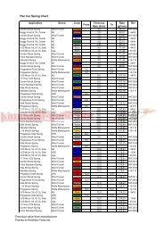
PHOTON SETUP RECORD<br />
Name: Date: Track:<br />
Condition:<br />
Temperature:<br />
Rubber Asphalt Edition<br />
Foam Carpet Edition<br />
CASTOR<br />
4-deg<br />
6-deg<br />
8-deg<br />
FRONT DRIVE<br />
Spool<br />
TOE<br />
Diff.<br />
One-Way<br />
deg<br />
MARK POSITION<br />
1.0mm<br />
2 holes<br />
1.2mm<br />
2 holes<br />
FF<br />
mm<br />
1.0mm<br />
3 holes<br />
1.2mm<br />
3 holes<br />
FRONT DIFF.<br />
TENSION<br />
FRONT MEASUREMENTS<br />
FRONT SHOCKS<br />
Tight<br />
RIDE HEIGHT mm OIL WEIGHT wt<br />
Medium<br />
CAMBER ANGLE deg PISTON Standard/Optional<br />
Loose<br />
DROOP mm BLADDER<br />
WHEEL HUBS mm SPRING<br />
FR<br />
mm<br />
VERTICAL<br />
ACKERMANN<br />
Forward<br />
Middle<br />
Rearward<br />
FRONT WING<br />
Rubber Asphalt<br />
Carpet Foam<br />
Other ________<br />
RADIAL<br />
ACKERMANN<br />
WHEEL SPACER mm NOTE<br />
MARK POSITION<br />
1.0mm<br />
2 holes<br />
1.0mm<br />
3 holes<br />
1.2mm<br />
2 holes<br />
1.2mm<br />
3 holes<br />
REAR MEASUREMENTS<br />
REAR SHOCKS<br />
TOP DECK<br />
Rubber Asphalt<br />
Carpet Foam<br />
Other ________<br />
RIDE HEIGHT mm OIL WEIGHT wt<br />
CAMBER ANGLE deg PISTON Standard/Optional<br />
DROOP mm BLADDER<br />
WHEEL HUBS mm SPRING<br />
WHEEL SPACER mm NOTE<br />
RF<br />
mm<br />
REAR WING<br />
Rubber Asphalt<br />
Carpet Foam<br />
Other ________<br />
MOTOR<br />
SPUR GEAR<br />
BRAND<br />
FRONT<br />
REAR<br />
REAR DIFF.<br />
TENSION<br />
PINION GEAR<br />
BATTERY<br />
COMPOUND<br />
INSERT<br />
Tight<br />
BODY SHELLS<br />
WHEEL<br />
Medium<br />
WING<br />
TIRE TREATMENT<br />
Loose<br />
ESC SETTING<br />
RR<br />
mm<br />
STEERING BLOCK<br />
Original<br />
Alloy<br />
REAR HUB CARRIER<br />
Original<br />
Alloy<br />
FRONT<br />
REAR<br />
5 4 3 2 1<br />
6 5 4 3 2 1<br />
3 2 1<br />
3 2 1<br />
mm<br />
mm<br />
mm<br />
mm<br />
mm<br />
mm<br />
CAMBER PLATE<br />
Standard<br />
Optional<br />
CAMBER PLATE<br />
Standard<br />
Optional<br />
mm<br />
2 3 1<br />
mm<br />
mm<br />
2 3 1<br />
mm<br />
mm<br />
FF<br />
FR<br />
mm<br />
mm<br />
RF<br />
RR<br />
Toe-Out = (FF-FR) / 0.8<br />
= deg<br />
H H M M L L<br />
Toe-In = (RR-RF) / 0.8<br />
= deg<br />
H H M M L L<br />
Page 28
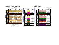
PHOTON SETUP RECORD<br />
Name: Date: Track: Rubber Std. Setup<br />
Condition:<br />
Temperature:<br />
X Rubber Asphalt Edition<br />
Foam Carpet Edition<br />
CASTOR<br />
X 4-deg<br />
6-deg<br />
8-deg<br />
FRONT DIFF.<br />
TENSION<br />
Tight<br />
Medium<br />
Loose<br />
FF 1.5 mm<br />
FR 1.5 mm<br />
VERTICAL<br />
ACKERMANN<br />
Forward<br />
Middle<br />
X Rearward<br />
FRONT DRIVE<br />
X Spool<br />
TOE 0.5 deg<br />
Diff.<br />
One-Way<br />
FRONT WING<br />
X Rubber Asphalt<br />
Carpet Foam<br />
Other ________<br />
RADIAL<br />
ACKERMANN<br />
MARK POSITION<br />
MARK POSITION<br />
1.0mm<br />
2 holes<br />
1.0mm<br />
3 holes<br />
FRONT MEASUREMENTS<br />
FRONT SHOCKS<br />
RIDE HEIGHT 5.0 mm OIL WEIGHT 40 wt<br />
CAMBER ANGLE 1.5 deg PISTON Standard/Optional<br />
DROOP 5.5 mm BLADDER STD.<br />
WHEEL HUBS STD 5.2 mm SPRING 14mm 1.5 x 6.00<br />
WHEEL SPACER 0.5 mm NOTE<br />
1.0mm<br />
2 holes<br />
1.0mm<br />
3 holes<br />
X<br />
X<br />
1.2mm<br />
2 holes<br />
1.2mm<br />
3 holes<br />
1.2mm<br />
2 holes<br />
1.2mm<br />
3 holes<br />
REAR MEASUREMENTS<br />
REAR SHOCKS<br />
TOP DECK<br />
X Rubber Asphalt<br />
Carpet Foam<br />
Other ________<br />
X<br />
RIDE HEIGHT 5.0 mm OIL WEIGHT 40 wt<br />
CAMBER ANGLE 1.5 deg PISTON Standard/Optional<br />
DROOP 5.5 mm BLADDER STD.<br />
WHEEL HUBS STD 5.2 mm SPRING 14mm 1.5 x 6.50<br />
WHEEL SPACER 1.0 mm NOTE<br />
RF 2.0 mm<br />
REAR WING<br />
X Rubber Asphalt<br />
Carpet Foam<br />
Other ________<br />
MOTOR<br />
SPUR GEAR<br />
FRONT REAR<br />
BRAND Sorex Sorex<br />
REAR DIFF.<br />
TENSION<br />
Tight<br />
PINION GEAR<br />
BATTERY<br />
7.4V 5000mAh 40C<br />
BODY SHELLS PF Mazda Speed 6<br />
COMPOUND 36R 36R<br />
INSERT HaraV3 HaraV3<br />
WHEEL Solaris Solaris<br />
X Medium<br />
WING<br />
STD.<br />
TIRE TREATMENT FX-II FX-II<br />
Loose<br />
ESC SETTING<br />
RR 1.5 mm<br />
STEERING BLOCK<br />
X Original<br />
Alloy<br />
REAR HUB CARRIER<br />
X Original<br />
Alloy<br />
5 4 3 2 1<br />
X<br />
FRONT<br />
2.5 mm<br />
3 2 1<br />
X<br />
6 5 4 3 2 1<br />
X<br />
REAR<br />
2.5 mm<br />
3 2 1<br />
X<br />
2.5 mm<br />
0.0 mm<br />
1.5 mm<br />
2.5 mm<br />
CAMBER PLATE<br />
X Standard<br />
Optional<br />
X<br />
CAMBER PLATE<br />
X Standard<br />
Optional<br />
1.2 mm<br />
2 3 1<br />
X<br />
0.0 mm<br />
1.2 mm<br />
2 3 1<br />
X<br />
0.8 mm<br />
0.0 mm<br />
FF<br />
FR<br />
X<br />
X<br />
1.0 mm<br />
3.4 mm<br />
RF<br />
RR<br />
X<br />
X<br />
Toe-Out = (FF-FR) / 0.8<br />
1.0 = 1.0 deg<br />
H H M M L L<br />
X<br />
Toe-In = (RR-RF) / 0.8<br />
3.0 = 3.0 deg<br />
H H M M L L<br />
Page 29
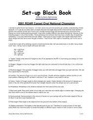
PHOTON SETUP RECORD<br />
Name: Date: Track: Foam Std. Setup<br />
Condition:<br />
Temperature:<br />
Rubber Asphalt Edition<br />
X Foam Carpet Edition<br />
CASTOR<br />
X 4-deg<br />
6-deg<br />
8-deg<br />
FRONT DIFF.<br />
TENSION<br />
Tight<br />
X<br />
Medium<br />
Loose<br />
FF 1.5 mm<br />
FR 1.5 mm<br />
VERTICAL<br />
ACKERMANN<br />
Forward<br />
Middle<br />
X Rearward<br />
FRONT DRIVE<br />
Spool<br />
TOE 1.0 deg<br />
X Diff.<br />
One-Way<br />
FRONT WING<br />
Rubber Asphalt<br />
X Carpet Foam<br />
Other ________<br />
RADIAL<br />
ACKERMANN<br />
X<br />
MARK POSITION<br />
MARK POSITION<br />
1.0mm<br />
2 holes<br />
1.0mm<br />
3 holes<br />
1.0mm<br />
2 holes<br />
1.0mm<br />
3 holes<br />
1.2mm<br />
2 holes<br />
X 1.2mm<br />
3 holes<br />
FRONT MEASUREMENTS<br />
FRONT SHOCKS<br />
RIDE HEIGHT 4.2 mm OIL WEIGHT 60 wt<br />
CAMBER ANGLE 2.5 deg PISTON Standard/Optional<br />
DROOP 5.0 mm BLADDER STD.<br />
WHEEL HUBS STD 5.2 mm SPRING 13mm 1.7 x 6.75<br />
WHEEL SPACER 1.0 mm NOTE<br />
1.2mm<br />
2 holes<br />
X 1.2mm<br />
3 holes<br />
REAR MEASUREMENTS<br />
REAR SHOCKS<br />
TOP DECK<br />
Rubber Asphalt<br />
X Carpet Foam<br />
Other ________<br />
RIDE HEIGHT 4.5 mm OIL WEIGHT 40 wt<br />
CAMBER ANGLE 3.0 deg PISTON Standard/Optional<br />
DROOP 5.0 mm BLADDER STD.<br />
WHEEL HUBS STD 5.2 mm SPRING 13mm 1.4 x 6.25<br />
WHEEL SPACER 0.0 mm NOTE<br />
RF 3.5 mm<br />
REAR WING<br />
Rubber Asphalt<br />
X Carpet Foam<br />
Other ________<br />
MOTOR<br />
SPUR GEAR<br />
4.5 BL<br />
64P-112T<br />
FRONT REAR<br />
BRAND Jaco Jaco<br />
REAR DIFF.<br />
TENSION<br />
Tight<br />
PINION GEAR<br />
BATTERY<br />
BODY SHELLS<br />
64P-25T<br />
7.4V LiPo<br />
R9F<br />
COMPOUND MAG. MAG.<br />
INSERT N/A N/A<br />
WHEEL N/A N/A<br />
X Medium<br />
Loose<br />
WING<br />
STD.<br />
ESC SETTING KO Propo 1.5<br />
TIRE TREATMENT Jack Jack<br />
RR 0.0 mm<br />
STEERING BLOCK<br />
X Original<br />
Alloy<br />
REAR HUB CARRIER<br />
X Original<br />
Alloy<br />
5 4 3 2 1<br />
X<br />
FRONT<br />
2.5 mm<br />
3 2 1<br />
X<br />
6 5 4 3 2 1<br />
X<br />
REAR<br />
N/A mm<br />
3 2 1<br />
X<br />
2.0 mm<br />
0.0 mm<br />
2.0 mm<br />
4.0 mm<br />
CAMBER PLATE<br />
X Standard<br />
Optional<br />
X<br />
CAMBER PLATE<br />
X Standard<br />
Optional<br />
1.4 mm<br />
2 3 1<br />
X<br />
1.0 mm<br />
mm<br />
2 3<br />
1<br />
X<br />
1.0 mm<br />
1.0 mm<br />
FF<br />
FR<br />
X<br />
X<br />
1.0 mm<br />
3.4 mm<br />
RF<br />
RR<br />
X<br />
X<br />
Toe-Out = (FF-FR) / 0.8<br />
0.0 = 0.0 deg<br />
H H M M L L<br />
X<br />
Toe-In = (RR-RF) / 0.8<br />
3.0 = 3.0 deg<br />
H H M M L L<br />
Page 30
STANDARD SPARE PARTS AND OPTIONAL PARTS LIST<br />
STANDARD SPARE PARTS<br />
Kit<br />
TC-PRK001 Photon 1/10 Rubber Edition<br />
TC-PRK001 Photon 1/10 Foam Edition<br />
Chassis<br />
TC-PCH011RD Bulkhead (Red)<br />
TC-PCH012RD Steering Mount Plate (Red)<br />
TC-PCH013RD Motor Plate (Red)<br />
TC-PCH014RD Motor Plate Support (Red)<br />
TC-PCH015RD Mount Plate (Red)<br />
TC-PCH016RD Standoff Post (Red) (2 pcs) - Foam Std.<br />
TC-PCH017RD Steering Post (Red)<br />
TC-PCH20F Foam Bumper - Foam Standard<br />
TC-PCH20R Foam Bumper - Rubber Std.<br />
TC-PCHC01 6-Cell Chassis 2.5mm - Rubber Std.<br />
TC-PCHC04 Top Deck Soft 2.0mm - Rubber Std.<br />
TC-PCHC08 Camber Link Plate 2.5mm<br />
TC-PCHC09 Wing Soft 2.0mm - Rubber Std.<br />
TC-PCHC10 Wing Hard 2.0mm - Foam Std.<br />
TC-PCHS02 6-Cell Chassis 3.0mm - Foam Std.<br />
TC-PCHS05 Top Deck Hard 2.5mm - Foam Std.<br />
TC-PCHS06 Front Shock Tower<br />
TC-PCHS07 Rear Shock Tower<br />
TC-PMNS01 Battery Brace Set<br />
TC-PMPS01 Servo Arm & Mount<br />
TC-PMQS01 Bumper & Body Post Set<br />
SK-CH1002 Body Post Set<br />
Drive Train<br />
PA-DR0001 Diff. Ring (2 pcs)<br />
PA-SDB324 3mm Steel Balls (24pcs)<br />
TC-PDT002RD Alloy Diff. Outdrives<br />
TC-PDT005RD Center Pulley Shaft (Red)<br />
TC-PDT006M Rear Belt<br />
TC-PDT007M Front Belt<br />
TC-PDTS01 Thrust Bearing Set<br />
TC-PDTS02 Diff. Screw Set<br />
TC-PMJS01 Spool Set<br />
TC-PMK104 Spool Outdrives (4 pcs)<br />
TC-PML104 Bearing Cam (4 pcs)<br />
TC-PMLS01 40T Diff. Pulley<br />
TC-PMLS02 20T Center Pulley<br />
Drive Shaft<br />
PO-DT0006 C-Joint Blades (4 pcs)<br />
PO-DT1004RD 5.2mm Wheel Adapter Set (Red)(4 sets)<br />
PO-SDT008 Universal Bone Ver. 2 (1 pc)<br />
PO-SDT009RD Al. Universal Bone Ver. 2 (Red) (1 pcs)<br />
PO-SDT018 Axle Shaft Ver. 3 (1 pc)<br />
PO-SDT019 Anti-Slip Universal Joint Set (1 pc)<br />
PO-SDT020 Universal Shaft Set V.3 (2 sets)<br />
PO-SDT021RD Al. Universal Shaft Set V.3 (Red) (2 sets)<br />
Ball Bearing<br />
PA-SB0805 Ball Bearing 5 x 8 x 2.5mm (2 pcs)<br />
PA-SB1005 Ball Bearing 5 x 10 x 4mm (8 pcs)<br />
PA-SB1510 Ball Bearing 10 x 15 x 4mm (4 pcs)<br />
Suspension<br />
TC-PMES01 F & R Suspension Arm (each 1 pc)<br />
TC-PMFS01 Castor Block - 4 deg.<br />
TC-PMGS01 Steering Block & R. Hub Carrier (1 each)<br />
TC-PMMS01 Suspension Mount Set<br />
TC-PSU001 3mm x 23mm Hinge Pin (2 pcs)<br />
TC-PSU002 3mm x 51mm Hinge Pin (2 pcs)<br />
TC-PSU007 Suspension Mount Insert (2 pcs)<br />
4152-P4S1 King Pin Collar (4 pcs)<br />
TC-PSUS01 Suspension Mount Spacer Set<br />
Shock Absorber<br />
TC-PMMS02 Shock Parts<br />
TC-PMRS01 Shock Piston Parts<br />
TC-PSH002 Shock Bladder (4 pcs)<br />
TC-PSH007<br />
TC-PSH101RD<br />
TC-PSHS01RD<br />
Stabilizer<br />
TC-PSBS01<br />
TC-PSB012<br />
TC-PSB014<br />
TC-PSU003RD<br />
TC-PSU006RD<br />
Steering<br />
TC-PMIS01<br />
Shock Spring<br />
PS-TR15600<br />
PS-TR15650<br />
PS-TF17675<br />
PS-TF14625<br />
Spur Gear<br />
SG-K64100<br />
Linkage<br />
TC-PSU005<br />
PA-HBS003<br />
TC-PMHS01<br />
TC-PMHS02<br />
Accessories<br />
PA-AT0001<br />
PA-AP0001<br />
PA-BPS3SV<br />
PA-ER0020<br />
PP-010320<br />
AW-BW31RD<br />
AW-BW32RD<br />
Spacers<br />
AW-S050RD<br />
AW-S100RD<br />
AW-S150RD<br />
AW-S200RD<br />
AW-S250RD<br />
AW-M050RD<br />
AW-M100RD<br />
AW-M200RD<br />
Screw<br />
PA-CM2506BK<br />
PA-BM0306BK<br />
PA-BM0308BK<br />
PA-CM0306BK<br />
PA-CM0308BK<br />
PA-CM0310BK<br />
PA-CM0314BK<br />
PA-CM0316BK<br />
Nut<br />
PA-FN00M3<br />
AW-LNF4RD<br />
Set Screw<br />
PA-SS0303BK<br />
PA-SS0306BK<br />
PA-SS0308BK<br />
PA-SS0310BK<br />
PA-SS0312BK<br />
Chassis<br />
PO-PCHC001<br />
PO-PCHS002<br />
PO-PCHC003<br />
PO-PCHC004<br />
PO-PCHC005<br />
PO-PCHC006<br />
PO-PBW101<br />
PO-PBW102<br />
PO-PCW030<br />
Shock Shaft (2 pcs)<br />
Shock Body Set (each 1 pc)<br />
Shock Set (2 sets)<br />
Stabilizer Bar Set<br />
1.2mm Stabilizer Bar (2 pcs) - Rubber Std.<br />
1.4mm Stabilizer Bar (2pcs) - Foam Std.<br />
Threaded Sway Bar Adjuster (Red) (2 pcs)<br />
Stabilizer Mount<br />
Bell Crank Set<br />
Gamma Spring 334gf/mm, 19.2lb/in (2 pcs)<br />
Gamma Spring 306gf/mm, 17.1lb/in (2 pcs)<br />
Alpha Spring 560gf/mm, 31.3lb/in (2 pcs)<br />
Beta Spring 306gf/mm, 17.1lb/in (2 pcs)<br />
Spur Gear 64P 100T Std.<br />
3mm x 30mm Tie Rod Steel (2 pcs)<br />
5.3mm Steel Ball (5 pcs)<br />
Ball Cup 14.5mm (8 pcs)<br />
Ball Cup 18.5mm (4 pcs)<br />
Antenna Tube (4 pcs)<br />
Antenna Post (2 pcs)<br />
Short Body Clip M6 Silver (20 pcs)<br />
M2 E-Clip (30 pcs)<br />
Oil Mixed O-Ring for Dampers 30 o<br />
Small M3 Beveled Washer Red (10 pcs)<br />
Large M3 Beveled Washer Red (10 pcs)<br />
3mm x 0.5t Collar Red (10 pcs)<br />
3mm x 1.0t Collar Red (10 pcs)<br />
3mm x 1.5t Collar Red (10 pcs)<br />
3mm x 2.0t Collar Red (10 pcs)<br />
3mm x 2.5t Collar Red (10 pcs)<br />
Wide 3mm x 0.5t Collar Red (10 pcs)<br />
Wide 3mm x 1.0t Collar Red (10 pcs)<br />
Wide 3mm x 2.0t Collar Red (10 pcs)<br />
Countersunk Cap Screw M2.5 x 6 (8 pcs)<br />
Button Head Screw M3 x 6 (10 pcs)<br />
Button Head Screw M3 x 8 (10 pcs)<br />
Countersunk Cap Screw M3 x 6 (10 pcs)<br />
Countersunk Cap Screw M3 x 8 (10 pcs)<br />
Countersunk Cap Screw M3 x 10 (10 pcs)<br />
Countersunk Cap Screw M3 x 14 (8 pcs)<br />
Countersunk Cap Screw M3 x 16 (8 pcs)<br />
Flat Nut M3 (10 pcs)<br />
M4 Al. Flange Nylon Lock Nut Red (5 pcs)<br />
Steel Set Screw M3 x 3 (10 pcs)<br />
Steel Set Screw M3 x 6 (10 pcs)<br />
Steel Set Screw M3 x 8 (10 pcs)<br />
Steel Set Screw M3 x 10 (8 pcs)<br />
Steel Set Screw M3 x 12 (8 pcs)<br />
OPTIONAL PARTS<br />
Lipo Rubber Chassis (2.0mm)<br />
Lipo Foam Chassis (2.5mm)<br />
Top Deck Medium 2.0mm<br />
Camber Link Plate 1.25mm Offset (2 pcs)<br />
Rubber Wing Medium Set<br />
Foam Wing Extra Hard Set<br />
LiPo Brace Weight Set (90g)<br />
LiPo Brace Weight Set (40g)<br />
Center Lipo Weight (30g)<br />
PO-PLW005<br />
Drive Train<br />
PO-CDB312BK<br />
PO-CDB408BK<br />
PO-PDT001<br />
PO-PDT002<br />
Drive Shaft<br />
PO-SDT025RD<br />
PO-DT1006RD<br />
Ball Bearing<br />
PO-CBST04<br />
PO-CB1005<br />
PO-CB1510<br />
Cylindrical LiPo Weight (5g)<br />
3mm Ceramic Diff. Ball (12 pcs)<br />
1.6mm Ceramic Diff. Ball (8 pcs)<br />
Low Friction Drive Belt Rear<br />
Low Friction Drive Belt Front<br />
Al. Universal Bone 43mm (Red) (1 pc)<br />
6.2mm Wheel Adapter Set (Red) (4 sets)<br />
Ceramic Ball Bearing Set (14 pcs)<br />
Ceramic Ball Bearing 5 x 10 x 4mm<br />
Ceramic Ball Bearing 10 x 15 x 4mm<br />
Shock Absorber<br />
PP-010321 Oil Mixed O-Ring for Dampers 40 o (10 pcs)<br />
Stabilizer<br />
TC-PSB010<br />
TC-PSB012<br />
TC-PSB014<br />
TC-PSB016<br />
TC-PSB018<br />
Shock Spring<br />
PS-TR15550<br />
PS-TR15575<br />
PS-TR15600<br />
PS-TR15625<br />
PS-TR15650<br />
PS-TR15675<br />
PS-TF17625<br />
PS-TF17650<br />
PS-TF17675<br />
PS-TF17700<br />
PS-TF17725<br />
PS-TF14575<br />
PS-TF14600<br />
PS-TF14625<br />
PS-TF14650<br />
PS-TF14675<br />
1.0mm Stabilizer Bar (2 pcs)<br />
1.2mm Stabilizer Bar (2 pcs)<br />
1.4mm Stabilizer Bar (2 pcs)<br />
1.6mm Stabilizer Bar (2 pcs)<br />
1.8mm Stabilizer Bar (2 pcs)<br />
Gamma Spring 393gf/mm, 22.0lb/in (2 pcs)<br />
Gamma Spring 367gf/mm, 20.5lb/in (2 pcs)<br />
Gamma Spring 344gf/mm, 19.2lb/in (2 pcs)<br />
Gamma Spring 324gf/mm, 18.1lb/in (2 pcs)<br />
Gamma Spring 306gf/mm, 17.1lb/in (2 pcs)<br />
Gamma Spring 289gf/mm, 16.2lb/in (2 pcs)<br />
Alpha Spring 626gf/mm, 35.0lb/in (2 pcs)<br />
Alpha Spring 591gf/mm, 33.1lb/in (2 pcs)<br />
Alpha Spring 560gf/mm, 31.3lb/in (2 pcs)<br />
Alpha Spring 532gf/mm, 29.8lb/in (2 pcs)<br />
Alpha Spring 507gf/mm, 28.3lb/in (2 pcs)<br />
Beta Spring 347gf/mm, 19.4lb/in (2 pcs)<br />
Beta Spring 325gf/mm, 18.2lb/in (2 pcs)<br />
Beta Spring 306gf/mm, 17.1lb/in (2 pcs)<br />
Beta Spring 294gf/mm, 16.2lb/in (2 pcs)<br />
Beta Spring 274gf/mm, 15.3lb/in (2 pcs)<br />
Note:<br />
1. Gamma Spring Series is designed for rubber asphalt racing<br />
2. Alpha and Beta Spring Series are designed for foam carpet<br />
racing (Alpha for front and Beta for rear).<br />
Spur Gear<br />
SG-K64088<br />
SG-K64096<br />
SG-K64104<br />
SG-K64108<br />
SG-K64112<br />
SG-K64116<br />
Linkage<br />
PO-PSU004RD<br />
Accessories<br />
PA-BT1005RD<br />
Nut<br />
AW-FN03RD<br />
AW-SNF4RD<br />
Set Screw<br />
PA-SS0303<br />
PA-SS0306<br />
PA-SS0308<br />
PA-SS0310<br />
PA-SS0312<br />
Screws<br />
PO-SSSST1<br />
PO-TISST1<br />
Spur Gear 64P 88T<br />
Spur Gear 64P 96T<br />
Spur Gear 64P 104T<br />
Spur Gear 64P 108T<br />
Spur Gear 64P 112T<br />
Spur Gear 64P 116T<br />
3mm x 30mm Al. Tie Rod Red (2 pcs)<br />
Belt Tensioner Set (Red)<br />
Al. M3 Flat Nut Red (5 pcs)<br />
M4 Al. Self-Locking Wheel Nut Red (4 pcs)<br />
M3 x 3 Stainless Steel Set Screw (10 pcs)<br />
M3 x 6 Stainless Steel Set Screw (10 pcs)<br />
M3 x 8 Stainless Steel Set Screw (10 pcs)<br />
M3 x 10 Stainless Steel Set Screw (10 pcs)<br />
M3 x 12 Stainless Steel Set Screw (10 pcs)<br />
Stainless Steel Screw Set<br />
Titanium Screw Set<br />
IMPORTANT: Stainless steel and titanium screws cannot be<br />
used for the installation of suspension mounts of Photon. Use<br />
original screws for these locations.<br />
Page 31
TOKYO HOBBIES CORP.<br />
1-10-9 Kamagaya, kamagaya-shi, Chiba, Japan<br />
Tel/Fax: +81.47.441.2570<br />
Email: info@tokyo-hobbies.com<br />
Website: www.top-racing.jp