
Create successful ePaper yourself
Turn your PDF publications into a flip-book with our unique Google optimized e-Paper software.
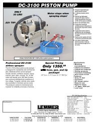
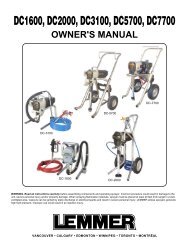
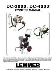
AIR SPRAY EQUIPMENT<br />
OWNER'S MANUAL<br />
A-900 <strong>Air</strong><br />
Spray Gun<br />
A-928S HVLP<br />
Spray Gun<br />
A-711 HVLP<br />
venturi gun<br />
A-928G HVLP<br />
Spray Gun<br />
A-930G HVLP<br />
Spray Gun<br />
2 Quart<br />
2 1/4 Gallon<br />
2 1/4 Gallon Pressure<br />
5 Gallon Pressure pot<br />
Pressure pot<br />
Pressure pot<br />
pot with agitator<br />
with manual agitator<br />
Boxer 5<br />
supply pump<br />
Boxer 24<br />
transfer pump<br />
WARNING..Read all instructions carefully before assembling components and operating <strong>spray</strong>er. Incorrect procedure<br />
could result in damage to the unit, severe personal injury and/or property damage. When <strong>spray</strong>ing flammable<br />
materials, electric powered products must be placed at least 20 feet from target in a well-ventilated area. Vapours can<br />
be ignited by static discharge or electrical sparks and result in severe personal injury.<br />
VANCOUVER • CALGARY • EDMONTON • WINNIPEG • TORONTO • MONTRÉAL<br />
1
TABLE OF CONTENTS<br />
SAFETY PRECAUTIONS ................................................................................... 2 CLEANING INSTRUCTIONS:<br />
INTRODUCTION ................................................................................................ 3<br />
PRESSURE POTS ....................................................................................... 11<br />
AIR SPRAY GUNS - CONVENTIONAL: ....................................................... 3<br />
BOXER SYSEMS ........................................................................................ 12<br />
AIR SPRAY GUNS - HVLP: .......................................................................... 3<br />
ALL AIR GUNS ............................................................................................ 13<br />
PRESSURE FEEDING THE AIR GUNS: ...................................................... 3 MAINTENANCE:<br />
COMPRESSOR REQUIREMENTS .............................................................. 3<br />
A-711 HVLP GUN ........................................................................................ 14<br />
LEMMER WARRANTY ................................................................................. 3<br />
PRESSURE POT ........................................................................................ 14<br />
SPECIFICATIONS:<br />
A-900 & A-928 GUN .................................................................................... 15<br />
PRESSURE POTS ........................................................................................ 4 TROUBLESHOOTING GUIDE ................................................................. 16 & 17<br />
BOXER 5 & 24 .............................................................................................. 5 OTHER QUALITY LEMMER PRODUCTS ....................................................... 18<br />
A-711 ............................................................................................................. 6 HOSES & COMPONENTS FOR AIR SPRAY EQUIPMENT ............................. 19<br />
PRESSURE POT .......................................................................................... 6 PARTS LIST & DIAGRAM:<br />
A-900 ............................................................................................................. 6<br />
A-700 SERIES HVLP GUN ................................................................. 20 & 21<br />
A-928 ............................................................................................................. 7<br />
A-900 AIR GUN ........................................................................................... 22<br />
A-930 ............................................................................................................. 7<br />
A-928 AIR GUN ........................................................................................... 23<br />
SETTING UP OF UNIT - BOXER 5 .................................................................... 8<br />
A-930 HVLP GRAVITY GUN ....................................................................... 24<br />
SETTING UP OF UNIT - 2.25 GALLON PRESSURE POT ................................ 8<br />
2-1/4 GALLON PRESSURE POT ............................................................... 25<br />
PAINT PREPARATION & SELECTING THE PROPER FLUID SET ................... 9<br />
5 G PRESSURE POT W/MANUAL AGI ...................................................... 26<br />
PROPER SPRAYING TECHNIQUES ................................................................. 9<br />
2 QUART ..................................................................................................... 27<br />
OPERATING INSTRUCTIONS ................................................................. 10 & 11<br />
BOXER 5 ..................................................................................................... 27<br />
BOXER 24 ................................................................................................... 28<br />
DISTRIBUTION CENTRES ACROSS CANADA .............................................. 28<br />
WARNING<br />
1) Do not <strong>spray</strong> paints or other inflammable fluids<br />
indoors which have a flash point below 21 degree<br />
C, 70 degree F. Keep <strong>spray</strong> area well ventilated.<br />
Before <strong>spray</strong>ing, turn off all pilot lights and open<br />
flames.<br />
2) Wear a respirator which is approved for the<br />
product being <strong>spray</strong>ed.<br />
3) Do not use halogenated hydrocarbon solvents<br />
in this system; it contains aluminium parts and<br />
may explode. Cleaning agents, coatings, paints,<br />
and adhesives may contain halogenated hydrocarbon<br />
solvents. Don't take chances, consult your<br />
material supplier to be sure. (ex: methylene<br />
chloride and 1,1,1 - Trichlorethane)<br />
4) Caution: When a flammable liquid is <strong>spray</strong>ed<br />
there may be danger of fire or explosion<br />
especially in a closed area.<br />
5) Caution: Arcing parts. Keep the compressor at<br />
least 20 feet away from explosive vapours.<br />
6) Caution: Static electricity can be developed by<br />
<strong>spray</strong>ing. Ground unit and object to be <strong>spray</strong>ed.<br />
On electric units, unit power cord must be connected<br />
to a grounded outlet. Use only three wire<br />
extension cords. Static explosion can occur with<br />
ungrounded unit.<br />
7) Always follow safety precautions and warnings<br />
printed on paint container.<br />
8) Do not pull on hoses to move <strong>equipment</strong>, DO NOT<br />
kink or bend the hose sharply.<br />
9) Keep children or anyone not familiar with air <strong>spray</strong><br />
systems away from <strong>equipment</strong> and work area.<br />
10) Conductive metal containers must be used when<br />
flushing flammable fluids through the system.<br />
Always flush at low pressure with <strong>spray</strong> tip removed. A<br />
metal part of the <strong>spray</strong> gun must be held firmly against<br />
the grounded metal pail when flushing or relieving<br />
pressure from the gun.<br />
SAFETY PRECAUTIONS<br />
ATTENTION<br />
1) Ne jamais pulvériser à l’interieur un produit inflammable qui a<br />
un point éclair inférieur à 21 degrés C,70 degrés F. L’endroit où<br />
vous peinturez doit toujours être bien aéré. Avant de pulvériser<br />
s’assurer qu’il n’y a aucune flamme ou pilot (veilleuse) de fournaise<br />
en marche dans l’appartement.<br />
2) Servez-vous d’un masque respiratoire qui est certifié pour le<br />
produit que vous pulvérisez.<br />
3) Ne pas utiliser de solvants contenant des hydrocarbures<br />
halogénés avec ce matériel. Il contient des particules d'aluminium<br />
et peut exploser. Les agents de nettoyage, enduits, peintures et,<br />
adhésifs, peuvent contenir des solvants contenant des<br />
hydrocarbures halogénés. Soyez prudents; consultez votre<br />
fournisseur pour les informations nécessaires. (ex: méthylène<br />
chloride and 1,1,1 - Trichloréthane)<br />
4) Attention: La pulvérisaton d'un liquide inflammable peut entraîner<br />
un risque d'incendie ou d'explosion, surtout dans les espaces<br />
fermés.<br />
5) Attention: Étincelles électriques. Ne pas placer la compresseur à<br />
moins de 6 mètres des vapeurs explosives.<br />
6) Attention: La pression du produit que l’on pulvérise peut produire<br />
une charge électrostatique. Mettre le matériel et l'objet à<br />
pulvériser à la terre. Sur les modèles électriques, le cordon<br />
électrique doit être attaché à une prise de courrant reliée à terre. Le<br />
cordon de rallonge doit être à 3 fils. Des décharges d'électricité<br />
statique peuvent se produire si le matériel n'est pas mis à la terre.<br />
7) Toujours prendre les précautions nécessaires et observer toutes<br />
les consignes de sécurité figurant sur le pot de peinture.<br />
8) Il ne faut jamais essayer de déplacer l'appareil en tirant sur le tuyau. Il faut<br />
aussi éviter tout tortillement du tuyau.<br />
9) Les enfants et le personnes n'ayant aucune expérience<br />
avec ce genre de pulvérisateur doivent êtres gardés à l'écart<br />
de l'appareil et du chantier de travail.<br />
10) Quand on décharge des liquides inflammables il<br />
faut utiliser des pots conducteurs en métal. Quand on<br />
relâche la pression avec le pistolet, une partie métallique du<br />
pistolet doit être en contact avec le pot en métal muni de<br />
mise à la terre.<br />
2
CONGRATULATIONS on choosing a new <strong>Lemmer</strong> Spray<br />
System! Your <strong>Lemmer</strong> Spray System is exceptionally<br />
rugged in construction and designed to operate with the<br />
best possible delivery efficiency. Like any fine precision<br />
tool, its most efficient operation depends on a thorough<br />
knowledge of its operation capabilities and maintenance.<br />
With proper material preparation and maintenance, your<br />
<strong>Lemmer</strong> will produce beautiful, uniform finishing results for<br />
years to come.<br />
This manual covers a variety of air <strong>spray</strong> <strong>equipment</strong> which can<br />
be categorized as follows:<br />
AIR SPRAY GUNS - CONVENTIONAL:<br />
The A-900 which atomizes paint at 40 - 60 psi. The higher<br />
operating pressure results in the best possible finish.<br />
AIR SPRAY GUNS - HVLP:<br />
The A-711 / A-928 / A-930 which atomize paint at 2 - 10 psi.<br />
The lower operating pressure provides lowest possible over<strong>spray</strong><br />
mist with high speed application rates.<br />
PRESSURE FEEDING THE AIR GUNS:<br />
Advantages:<br />
• The <strong>spray</strong> gun can operate in any position, and fit in<br />
smaller areas.<br />
• The weight of the material is off the <strong>spray</strong> gun for less<br />
operator fatique.<br />
• A wider range of viscosities may be used with the same<br />
fluid nozzle.<br />
• Generally can increase application rates and reduce paint<br />
mist.<br />
• Saves time by requiring less fills.<br />
Fluid supply method:<br />
<strong>Lemmer</strong> pressurized containers are available in 2 quart<br />
remote, or 2.25 gallon remote. They are inexpensive and<br />
simple to operate.<br />
<strong>Lemmer</strong> low pressure pumps are available in two styles.<br />
The Boxer 5 is perfect for supplying constant steady<br />
pressure to multiple air <strong>spray</strong> guns. The Boxer 24 is not<br />
recommended for air gun supply but is for use as a transfer<br />
pump.<br />
COMPRESSOR REQUIREMENTS FOR MOST OF THESE<br />
SYSTEMS:<br />
For optimum results the air compressor should maintain a<br />
constant minimum air flow of 7 cfm at a minimum of 50 psi. <strong>Air</strong><br />
supply must be clean, dry, and oil free.<br />
LEMMER PAINT SPRAYING EQUIPMENT LIMITED WARRANTY<br />
LEMMER Spray Systems Ltd. extends to the original purchaser of its paint<br />
<strong>spray</strong> <strong>equipment</strong> a limited one year warranty from the date of purchase<br />
against defects in material or workmanship provided that the <strong>equipment</strong><br />
is installed and operated in accordance with the recommendations and<br />
instructions written in the owners manual. LEMMER Spray Systems Ltd.<br />
will repair or replace, at its option, defective parts without charge if such<br />
parts are returned (still intact in the original <strong>equipment</strong>) with transportation<br />
charges prepaid to the nearest LEMMER Spray Systems Ltd. outlet. An<br />
original proof of purchase must be attached.<br />
THIS WARRANTY DOES NOT COVER:<br />
Normal wear and/or defects caused by or related to abrasion, corrosion,<br />
abuse, negligence, accident, faulty installation or tampering in a manner<br />
which impairs normal operation.<br />
Transportation costs and other incidental, direct, special, or consequential<br />
damages or loss.<br />
INTRODUCTION<br />
Your <strong>Lemmer</strong> system is capable of <strong>spray</strong>ing a wide<br />
variety of lacquer, some epoxies, industrial finishes, latex,<br />
oil-based and alkyd paints, as well as stains, preservatives<br />
and other architectural coatings. The material you<br />
are <strong>spray</strong>ing will have a direct effect on the amount of<br />
pressure required for the optimum pattern and coverage<br />
to be obtained. We recommend that before actually<br />
beginning your job, you carefully read this manual and<br />
practice with the system until you feel comfortable using it.<br />
COATING APPLICATIONS<br />
COATING EXCELLENT GOOD NOT REC.<br />
Multi-colour (HVLP) X<br />
Stain<br />
X<br />
Sealers (concrete) X<br />
Asphalt Coating<br />
Primer<br />
X<br />
Elastomerics<br />
Varnish<br />
X<br />
Lacquer<br />
X<br />
Sealers (wood)<br />
X<br />
Acrylic<br />
X<br />
Textured<br />
X<br />
Block Filler<br />
Ext. Latex X*<br />
Ext. Oil Base X*<br />
Latex (Int.) X*<br />
Enamel (alkyd) X*<br />
*Some thinning may be required. Follow manufacturer’s<br />
recommendations.<br />
X<br />
X<br />
X<br />
3
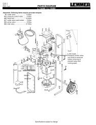
SPECIFICATIONS - PRESSURE POTS<br />
paint hose to<br />
<strong>spray</strong> gun. (black)<br />
WARNING: Make sure nuts<br />
and bolts are properly tightened<br />
before pressurizing the pot!<br />
fluid pressure<br />
regulator with<br />
guage.<br />
air <strong>spray</strong> gun<br />
fluid pressure<br />
regulator with<br />
guage.<br />
air cap pressure<br />
regulator with guage.<br />
line from air<br />
compressor.<br />
air hose to<br />
<strong>spray</strong> gun. (red)<br />
air <strong>spray</strong> gun<br />
line from air<br />
compressor.<br />
fluid<br />
paint hose<br />
to <strong>spray</strong><br />
gun. (black)<br />
air<br />
fluid<br />
air hose to<br />
<strong>spray</strong> gun. (red)<br />
air<br />
heavy<br />
duty<br />
clamps.<br />
safety<br />
valve,<br />
50 psi.<br />
safety<br />
valve,<br />
50 psi.<br />
teflon lined<br />
inner pot.<br />
Figure 1. - Typical 2 quart system<br />
DESCRIPTION:<br />
The following paragraphs refer to the 2 1/4 gallon system.<br />
The 2 quart system is basically the same other than size<br />
and not having a standard air regulator for the air cap air.<br />
The <strong>Lemmer</strong> pressure pot is designed for production line<br />
and decorator painting applications using internal or<br />
external mix <strong>spray</strong> guns. The pressure pot is capable of<br />
holding bulk quantities of paint or a one gallon paint can<br />
may be placed in the pressure pot without having to pour<br />
out can contents.<br />
Basic construction of the unit consists of a heavy deep<br />
drawn one piece galvanized steel pot, steel stamped pot<br />
lid, eyebolt clamp.<br />
The unit is equipped with a pressure regulator, gauge,<br />
safety relief and bleeder valve, paint line and air line<br />
connections. A convenient carrying handle allows attachment<br />
of the unit to the rung of a ladder or scaffolding to<br />
facilitate house or barn <strong>spray</strong>ing operations.<br />
Figure 2. - Typical 2 1/4 gallon system<br />
SPECIAL SAFETY PRECAUTIONS:<br />
• Do not pressurize pot over 50 PSI.<br />
• Make sure all feed line, eyebolts and <strong>spray</strong> guns are<br />
secured before turning air supply on.<br />
• Always shut off air pressure at source and bleed off<br />
all pressure in pressure pot by gently pulling safety<br />
valve ring before loosening knobs.<br />
• Regularly check to be sure gauge and regulator are<br />
functioning correctly. Also check that no paint nor<br />
other deposits are in safety valve inlet. In the event<br />
more than 50 PSI is applied to the pressure pot, and<br />
safety valve is clogged, the higher pressure could<br />
damage the pressure pot.<br />
• Only use original <strong>Lemmer</strong> replacement parts. These<br />
parts are safety performance engineered. Any substitutions<br />
may be counter-protective and dangerous.<br />
4
PUMP TYPE:<br />
These units are AIR POWERED DOUBLE DIAPHRAGM<br />
PUMPS. Top quality parts keep maintenance to a minimum. All<br />
paint valves are made of stainless steel for extra long abrasion<br />
resistance. The advantages of this type of pump is:<br />
- Minimal or no thinning of paint products<br />
- Pumps straight out of original paint container<br />
- Variable pressure<br />
- Boxer 5 is quiet running & and continues running even<br />
when <strong>spray</strong>ing stops to insure constant <strong>spray</strong> pressure<br />
- Boxer 24 is quiet running & and stops when flow stops. It is<br />
best suited for transfering liquids<br />
- Safe for hazardous locations - no electricity<br />
How Pneumatic pumps operate: A pneumatic pump consists<br />
of a reciprocating air motor and a fluid pump. Its speed and<br />
pressure are controled by air regulator. The pressure ratio<br />
(pump ratio) of the pump is determined by the square area of<br />
the air motor piston versus the square area of the piston in the<br />
fluid pump. The pumps maximum possible output pressure is<br />
determined by multiplying the ratio by the compressed air<br />
pressure fed into the air motor.<br />
Fluid pressure<br />
regulator<br />
Fluid outlet fliter<br />
Fluid outlet<br />
Fluid inlet<br />
Fluid inlet fliter<br />
<strong>Air</strong> pressure regulator<br />
<strong>Air</strong> shutoff<br />
valve<br />
<strong>Air</strong> motor<br />
piston<br />
<strong>Air</strong> logic valve<br />
<strong>Air</strong> valve shifter<br />
Figure 4. - Boxer 24 pump components<br />
SPECIFICATIONS - BOXER 5 & 24<br />
<strong>Air</strong> pressure<br />
regulator<br />
<strong>Air</strong> logic valve shft<br />
sensors (Boxer 5<br />
only)<br />
Fluid pump<br />
Figure 3. - Boxer 5 pump components<br />
Fluid outlet<br />
Outlet valve<br />
Fluid pump<br />
Inlet valve<br />
5<br />
Example:<br />
Pump ratio= 1:1<br />
<strong>Air</strong> pressure reading at air motor control= 71 psi<br />
Max. fluid pressure (1 x 71)= 71 psi<br />
The air is connected to the air motor of the pump. First, the<br />
pump is primed, then the pressure is set (lets say at 10 PSI for<br />
pumping latex). When the fluid pressure reaches 10 PSI in<br />
the hose, the:<br />
Boxer 5 pump cycles feely, waiting to deliver more fluid without<br />
delay. This uses about 2 cfm of air, but provides instant trigger<br />
response thus eliminating fan fluctuations.<br />
Boxer 24 fluid pump parts (including air motor) stop moving<br />
creating a stall position. When the flow valve is opened and the<br />
fluid pressure begins to drop, the air motor and fluid pump<br />
immediately begin to work to maintain pressure. The results are<br />
minimal air consumption and minimal all-around wear.<br />
PUMP COMPONENTS:<br />
Spray Gun: The <strong>spray</strong> gun is supplied separately and may be<br />
of a standard high pressure air design, or of the HVLP low<br />
pressure design.<br />
<strong>Air</strong> motor: These specially designed air motors convert the<br />
energy from compressed air into a double action stroke. Both<br />
the left and right power strokes are used by the fluid pump to<br />
create pressure and volume. The air motors are permanently<br />
lubricated and require minimal maintenance. Its air source must<br />
be regulated, clean, and free of oil.<br />
Fluid Pump: The fluid pump is a double diaphragm with inlet<br />
and outlet valves on each side. The diaphragm is made of a<br />
tough nylon resin blend and the housing of polyarilammide<br />
material for best chemical and abrasion resistance.<br />
Pressure regulator: The pressure regulator is on the top of the<br />
air motor. When the regulator handle is turned clockwise, air<br />
pressure is increased, when the handle is turned counterclockwise,<br />
air pressure is reduced.<br />
Always reduce the pressure (turn the handle all the way<br />
counterclockwise, or disconnect air supply) when cleaning or<br />
when switching the position of the dump valve (if so equipped).<br />
Dump Valve (if equipped): The dump valve is located on the<br />
side of the fluid pump. When turned to “prime” (handle in-line<br />
with body), it circulates fluid to vent the air trapped in the fluid<br />
pump out the return hose. It will continue to recirculate the fluid<br />
until the knob is manually turned to the “<strong>spray</strong>” position.<br />
When the dump valve is turned to “<strong>spray</strong>”, flow is shut off<br />
through the return hose and is routed to the fluid hose for<br />
<strong>spray</strong>ing or transferring.<br />
The dump valve also serves to relieve pressure on the system<br />
during shutdown and cleanup. The pressure is relieved by<br />
turning the prime valve to “dump”.<br />
COATINGS:<br />
Most types of paints and coatings are supplied ready to <strong>spray</strong><br />
(with the exception of possible thinning). In possible instances<br />
where a coating is contaminated with foreign particles, Boxer<br />
units are available with inlet filter screens, and a high pressure<br />
outlet filter to prevent possible plugging or damage.<br />
Viscosity alone is no measure for good pump priming,<br />
pumpability or <strong>spray</strong>ability. It may well be that a suction hose<br />
has to be exchanged for a straight suction tube, or a shorter<br />
tube to assist the priming action.<br />
Two-component materials generally have a short “pot life”. The<br />
unit must be properly flused and cleaned well before the curing<br />
time starts.<br />
Pumping coarse bodied or aggressive fluids is possible up to<br />
about 3mm maximum diameter particles.
Figure 5. - Typical pressure pot system<br />
Special safety precautions:<br />
• Do not pressurize tank over 50 PSI.<br />
• Make sure all feed line, eyebolts and <strong>spray</strong> guns are<br />
secured before turning air supply on.<br />
• Always shut off air pressure at source and bleed off<br />
all pressure in paint tank by gently pulling safety valve<br />
ring before loosening knobs.<br />
• Regularly check to be sure gauge and regulator are<br />
functioning correctly. Also check that no paint nor<br />
other deposits are in safety valve inlet. In the event<br />
more than 50 PSI is applied to the tank, and safety<br />
valve is clogged, the higher pressure could damage<br />
the tank.<br />
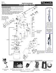
SPECIFICATIONS - A-711<br />
Fan width<br />
control.<br />
Spray pattern<br />
control air cap.<br />
Important: A pressure<br />
regulator must be used<br />
between the air<br />
compressor and the<br />
<strong>spray</strong> gun. The regulator<br />
wil also serve as the<br />
air control valve in<br />
controlling air flow<br />
through the <strong>spray</strong> gun.<br />
A-711 HVLP SPRAY GUN WITH PRESSURIZED CUP:<br />
As high speed compressed air passes through the venturi<br />
assembly, a low pressure field is created. Ambient air<br />
(outside room air) is pulled through the air filter/silencer,<br />
mixing with the compressed air, and creating a high<br />
volume of low pressure air. Operating at standard air line<br />
pressures the A-711 venturi gun creates less than 10 psi<br />
at the gun while maintaining 65 - 95% transfer efficiency.<br />
Special safety precautions:<br />
The A-711 venturi gun is a non bleeder type with continuous<br />
pressure in the cup, even after the air line has been<br />
disconnected! Do Not pull trigger after <strong>spray</strong>ing!<br />
Release pressure with the cup locking lever immediately<br />
after use. Wear eye protection!<br />
SPECIFICATIONS - PRESSURE POT<br />
DESCRIPTION:<br />
The <strong>Lemmer</strong> paint tank is designed for production line<br />
and decorator painting applications using internal or<br />
external mix <strong>spray</strong> guns. The tank is capable of holding<br />
bulk quantities of paint or a one gallon paint can may be<br />
placed in the tank without having to pour out can contents.<br />
Basic construction of the unit consists of a heavy deep<br />
drawn one piece galvanized steel tank, steel stamped<br />
tank lid, eyebolt clamp.<br />
The unit is equipped with a pressure regulator, gauge,<br />
safety relief and bleeder valve, paint line and air line<br />
connections. A convenient carrying handle allows attachment<br />
of the unit to the rung of a ladder or scaffolding to<br />
Material<br />
volume<br />
control knob.<br />
Venturi<br />
intake filter.<br />
<strong>Air</strong> hose inlet.<br />
Pressure cup.<br />
6<br />
facilitate house or barn <strong>spray</strong>ing operations.<br />
WARNING: Failure to follow instructions on proper<br />
assembly and use of a paint tank may possibly result<br />
in damage to property or personal injury. This unit<br />
must be assembled as indicated in these instructions.<br />
Only those parts supplied with this unit should<br />
be used. These parts are safety performance engineered.<br />
Any substitutions may be counter-protective<br />
and dangerous.<br />
SPECIFICATIONS - A-900<br />
<strong>spray</strong> pattern<br />
plane control.<br />
container<br />
anti-drip<br />
vent.<br />
fan width<br />
control knob.<br />
material volume<br />
control knob.<br />
air volume<br />
control knob.<br />
air hose inlet.<br />
A-900 AIR SPRAY GUN WITH SUCTION POT:<br />
The A-900 conventional <strong>spray</strong> gun is designed for furniture<br />
fine finishing, auto body shops, metal fabrication<br />
shops, contractors, and hobbyists. The metal gun is<br />
durable and has a large pot opening for easy cleaning.<br />
Spray fan control is adjusted at the top back, horizontal<br />
and vertical pattern is controlled at the air cap, and<br />
material flow is controlled at the back of the gun. Materials<br />
which can be <strong>spray</strong>ed include varnish, urethane,<br />
lacquer, automotive paint, epoxy, enamel, stain, latex, oil<br />
base, etc. The gun comes with a 1 quart container, and<br />
can also be used with an optional 2 quart or 2-1/4 gallon<br />
remote pressure pot. The fluid needle and seat are made<br />
of stainless steel, and the entire gun can be placed in a<br />
gun cleaning cabinet. The gun is supplied with a 1.5 mm<br />
general purpose nozzle for thin materials such as varnish,<br />
stain, and enamels (latex and oil base require some extra<br />
thinning). Other sizes available separately, see parts list<br />
in back of book.
SPECIFICATIONS - A-928<br />
<strong>spray</strong> pattern<br />
plane control.<br />
fan width<br />
control knob.<br />
material volume<br />
control knob.<br />
SPECIFICATIONS - A-930<br />
Nylon gravity pot<br />
with screw on lid.<br />
container air<br />
pressure hose.<br />
container<br />
pressure<br />
regulates up<br />
to 10 psi.<br />
air hose inlet.<br />
air volume<br />
control knob.<br />
<strong>spray</strong> pattern<br />
plane control.<br />
material volume<br />
control knob.<br />
fan width<br />
control knob.<br />
A-928 HVLP SPRAY GUN WITH PRESSURIZED CUP:<br />
The A-928 HVLP <strong>spray</strong> gun is designed for furniture fine<br />
finishing, auto body shops, metal fabrication shops,<br />
contractors, and hobbyists. The metal gun is durable and<br />
has a large pot opening for easy cleaning. Spray fan<br />
control is adjusted at the top back, horizontal and vertical<br />
pattern is controlled at the air cap, and material flow is<br />
controlled at the back of the gun. Materials which can be<br />
<strong>spray</strong>ed include varnish, urethane, lacquer, automotive<br />
paint, epoxy, enamel, stain, latex, oil base, multi-colour<br />
etc. The gun comes with a 1 quart container, and can<br />
also be used with an optional 2 quart or 2-1/4 gallon<br />
remote pressure pot. The fluid needle and seat are made<br />
of stainless steel, and the entire gun can be placed in a<br />
gun cleaning cabinet. The gun is supplied with a 1.4 mm<br />
general purpose nozzle for materials such as varnish,<br />
stain, and enamels (latex and oil base require some extra<br />
thinning). Other sizes available separately, see parts list<br />
in back of book.<br />
air volume<br />
control knob.<br />
air hose inlet.<br />
A-930 HVLP AIR SPRAY GUN WITH GRAVITY POT:<br />
The A-930 HVLP is designed for low over<strong>spray</strong> and high<br />
production. Low over<strong>spray</strong> is achieved by converting<br />
compressor air to High Volume Low Pressure in the air<br />
cap. Applications for this <strong>spray</strong> gun include furniture fine<br />
finishing, auto body, metal fabrication, and most other<br />
<strong>spray</strong> type jobs. The metal gun is durable and has a light<br />
weight nylon gravity container with a non-drip screw-on<br />
lid. Spray fan control is adjusted on the side of the gun,<br />
horizontal and vertical pattern is controlled at the air cap,<br />
and material flow is controlled at the back of the gun.<br />
Materials which can be <strong>spray</strong>ed include varnish,<br />
urethane, lacquer, automotive paint, metalics, epoxy,<br />
enamel, stain, latex, oil base, multi-colour, etc. The gun<br />
comes with a 1/2 litre container. The fluid needle and seat<br />
are made of stainless steel, and the entire gun can be<br />
placed in a gun cleaning cabinet. This gun is supplied<br />
with a 1.5 mm general purpose nozzle for thin materials<br />
such as lacquer, stain, and enamels (latex and oil base<br />
require some extra thinning). Nozzle sizes 1.0, 2.0 & 2.5<br />
are available separately, see parts list in back of book.<br />
7
TOOLS NEEDED:<br />
2 x 8" or larger crescent wrench<br />
PROCEDURE:<br />
1. Remove all system components from the box for<br />
assembly.<br />
2. Remove all protective caps from inlet and outlet<br />
connections of pump.<br />
3. Attach suction hose or sucton pipe to inlet of pump.<br />
Tighten securely.<br />
4. Attach return hose or dump valve to fluid outlet fitting<br />
to approximately 20 ft. lbs.<br />
5. Connect fluid hose to pump outlet. Tighten to approximately<br />
20 ft. lbs.<br />
6. Connect the fluid hose to the connection of the <strong>spray</strong><br />
gun. Tighten to 20 ft. lbs.<br />
7. Double check all connections, the unit is now ready<br />
for flushing.<br />
Note: The pump contains a preservative oil when you<br />
receive it, that may drip from the various connections<br />
when the protective caps are removed.<br />
ASSEMBLY:<br />
1. Assemble the regulator to the paint tank lid as shown<br />
in the exploded view drawing.<br />
NOTE: This regulator is a special pressure limiting<br />
regulator. Your paint tank should be used only with<br />
this regulator. NEVER ASSEMBLE A REGULATOR TO<br />
YOUR PAINT TANK IN ANY OTHER MANNER.<br />
2. Install the handle (13) in the threaded hole in the<br />
center of the tank lid (3) as shown.<br />
3. Attach the material hose to the material hose connector<br />
(15).<br />
4. Connect the material hose and the air hose to the<br />
<strong>spray</strong> gun and check all fittings to make sure they are<br />
tight.<br />
5. Turn both regulators to minimum pressure<br />
(counterclockwise) and connect air supply. Slowly<br />
increase fluid pressure while watching for any leaks.<br />
6. Read page 8 "operating instructions" for correct<br />
pressure settings.<br />
SETTING UP OF UNIT - BOXER 5<br />
air control assembly.<br />
paint filter.<br />
attach fluid<br />
hose here.<br />
paint suction<br />
hose.<br />
suction filter.<br />
Figure 6. - Boxer 5 system components.<br />
SETTING UP OF UNIT - 2.25 GALLON PRESSURE POT<br />
8<br />
9 7<br />
from air<br />
compressor.<br />
(some models)<br />
7<br />
3<br />
5<br />
from air<br />
compressor.<br />
(newer models)<br />
10<br />
4<br />
12<br />
11<br />
air hose to<br />
<strong>spray</strong> gun.<br />
boxer pump.<br />
air <strong>spray</strong> gun<br />
13<br />
14<br />
16<br />
paint hose to<br />
<strong>spray</strong> gun.<br />
17<br />
18<br />
CAUTION: Do not use wrench or pliers to tighten<br />
knobs. Hand tighten only.<br />
CAUTION: Make certain that all pressures within the<br />
system are relieved before attempting to remove any<br />
component or part of a component.<br />
2<br />
21<br />
19<br />
20<br />
WARNING: Failure to follow instructions on proper<br />
assembly and use of a paint tank may possibly result<br />
in damage to property or personal injury. This unit<br />
must be assembled as indicated in these instructions.<br />
Only those parts supplied with this unit should be<br />
used. These parts are safety performance engineered.<br />
Any substitutions may be counter-protective<br />
and dangerous.<br />
8<br />
1<br />
Figure 7. - Pressure pot components<br />
WARNING:<br />
Make sure<br />
nuts and bolts<br />
are properly<br />
tightened<br />
before<br />
pressurizing<br />
the tank!
PAINT PREPARATION & SELECTING THE PROPER FLUID SET<br />
FLUID SET SELECTION:<br />
Nozzle sets range in size to provide different fluid flow<br />
rates. For low flow rates or light viscosity fluid, select the<br />
smaller nozzle sizes. For high flow rates or high viscosity<br />
fluid, select the larger nozzle sizes. For the best atomization,<br />
use the fluid nozzle that will give the required flow<br />
with the needle fully triggered.<br />
Measuring paint viscosity:<br />
1. Thin paint according to paint can instructions. Be<br />
certain to use a thinner which is compatible with paint<br />
used. If no thinning instructions are given, a general<br />
rule of thumb is 5 to 15% thinners. (fine finish up to<br />
35%)<br />
Get professional looking results by following the <strong>spray</strong><br />
tips below.<br />
1. Adjust air line pressure to 50 psi to start. Test the<br />
<strong>spray</strong> pattern, atomization, and over<strong>spray</strong> mist and<br />
adjust pressure up or down to obtain desired results.<br />
2. Keep the gun perpendicular to the surface. Always<br />
hold the gun perpendicular to the surface with the tip<br />
approximately 6 to 8" from the surface. If held at an<br />
angle (up and down or side to side) paint will build up<br />
unevenly and leave the work splotchy. This also<br />
saves material and reduces mist.<br />
3. Move with a smooth arm stroke Move the gun at a<br />
steady even pace while keeping the gun perpendicular<br />
to the surface. (See figure 8) Do not move the gun<br />
by flexing your wrist. Fanning the gun will cause<br />
excessive over<strong>spray</strong> and uneven coverage. (See<br />
figure 9). If the rate of speed is not comfortable for<br />
you, select another nozzle/needle size according to<br />
the nozzle charts.<br />
PROPER SPRAYING TECHNIQUES<br />
2. Stir paint completely and strain.<br />
3. Use the viscosity cup to measure paint as follows:<br />
a) Submerge the <strong>Lemmer</strong> Viscosity cup in the paint.<br />
b) Lift the cup out of the paint and begin timing.<br />
c) Stop timing when the steady paint stream is first<br />
broken.<br />
d) The time recorded is the paint’s viscosity.<br />
4. Now read the nozzle chart included with the <strong>spray</strong><br />
guns parts list and choose the nozzle which lists the<br />
viscosity range your material falls into.<br />
Note: The nozzle chart has been made as accurately as<br />
possible. Not all paints will exactly comply due to paint<br />
ingredient variations. However, it is an excellent starting<br />
point for learning the basics <strong>spray</strong> painting.<br />
Thin Materials: Decrease air flow through gun to minimize<br />
mist.<br />
Heavy Materials: If flow rate is too slow, additional<br />
thinning will be needed or a larger fluid nozzle will be<br />
required.<br />
4. Start moving the gun before triggering To get<br />
smooth overlap and prevent initial paint buildup, start<br />
your stroke movement before pulling the trigger. At<br />
the end of the stroke release the trigger before<br />
stopping.<br />
NOTES:<br />
For a nice even finish, always overlap previous strokes<br />
by the same amount, generally 50%. Put on a full wet<br />
coat whenever possible.<br />
When blending spots, work from the outside in. Start one<br />
inch out, no dusting. This eliminates “chronic halo” .<br />
Figure 8. - Proper way to trigger <strong>spray</strong> gun.<br />
Figure 9. - Result of flexing wrist while <strong>spray</strong>ing.<br />
9
OPERATING INSTRUCTIONS<br />
Whenever the system is to be used, it must be prepared<br />
for the type of paint to be used. This requires the<br />
system to be flushed out with an appropriate solvent<br />
(water for latex, mineral spirits for oil base, etc.).<br />
Incorrect flushing can cause gumming and priming<br />
problems.<br />
Caution: Never aim <strong>spray</strong> gun at any part of the body.<br />
Even when air line is disconnected, the <strong>spray</strong> gun may<br />
retain fluid pressure.<br />
Note: if using agitator accessory, set air control valve<br />
to slowest speed that air motor will operate. This will<br />
ensure proper mixing without splashing and aerating.<br />
7. Set the vertical/horizontal <strong>spray</strong> pattern:<br />
On A-900, A-925, A-930: loosen the air cap ring,<br />
rotate the air cap, and re-tighten the ring.<br />
On A-711: just turn the air cap. The aircap adjusting<br />
ring only requires to be loosened if it is set to its<br />
widest pattern (srewed in tight).<br />
Caution: Never use metal implements to clean out<br />
holes in the air cap or fluid tip.<br />
Caution: Before servicing the gun always shut off air<br />
and fluid supply and relieve all pressure.<br />
Warning: Be certain that the air line supply line is at<br />
zero psi and pressure regulators are turned to minimum<br />
before connecting any air supply!<br />
1. Securely connect either suction pot, gravity pot, or<br />
pressure feed hose. If using the suction pot have the<br />
bent suction pipe aiming forward (or backward if<br />
<strong>spray</strong>ing upwards). Connect the "zero pressure" air<br />
line.<br />
2. Adjust the volume knob on gun counter clockwise<br />
until full trigger movement is achived.<br />
3. Prepare your paint and pour into the paint container.<br />
It is normal to thin products for air application 10-20%,<br />
depending on manufacturers recommendations and job<br />
particulars.Thicker products require more air pressure<br />
for atomization, larger nozzle sizes, and higher material<br />
pressures. Prepare the surface to be painted according<br />
to the paint suppliers instructions.<br />
4. Practice on scrap material before proceeding to <strong>spray</strong>.<br />
5. Set the atomizing air pressure. The best pressure for<br />
any type of <strong>spray</strong>ing is the lowest pressure that will<br />
give a good finish. This is because lower <strong>spray</strong>ing<br />
pressures have less over<strong>spray</strong>. Depending on the type<br />
of paint and its thickness, this pressure will range from<br />
40 - 80 psi.<br />
6. If using a pressure feed system, adjust the paint<br />
pressure to about 5 psi. The material or "pot" pressure<br />
determines how much paint comes from the gun, i.e.)<br />
how wet is the coat. Best material pressures are<br />
between 5- 20 psi. (The gun can be fed from any<br />
pressure pot, or from any transfer pump system with a<br />
1:1 ratio).<br />
Be careful not to overpower the ability of the gun to<br />
atomize properly by using too much fluid pressure. To<br />
test for proper fluid pressure, disconnect atomizing air<br />
to the gun (by use of separate regulator, shut off valve,<br />
or simply by kinking the hose if air is regulated at the<br />
compressor) and pull trigger of <strong>spray</strong> gun fully, the<br />
material stream should travel 12" to 18" in a downward<br />
arch. Increase or decrease the regulator pressure as<br />
necessary to obtain proper material flow.<br />
10<br />
Round jet (A-711 only) Horizontal Fan Vertical Fan<br />
Figure 10. - Spray pattern control (turn air cap).<br />
8. Set the <strong>spray</strong> fan width:<br />
On A-900, A-925, A-930: use the knob at the side of<br />
the <strong>spray</strong> gun head, or at the back of the gun. Turning<br />
the knob in reduces the <strong>spray</strong> fan size, turning it out<br />
increases fan. The practical limit is about an 8 - 10 "<br />
fan one foot from the gun (will also adjust down to very<br />
small round <strong>spray</strong> pattern). Note: The air consumption<br />
decreases as you reduce the fan width.<br />
On A-711: turn the control ring in (for wide) or out (for<br />
narrow). Smoother finishes can be obtained by using a<br />
narrow pattern. More material output can be gained by<br />
using a wide pattern.<br />
wider <strong>spray</strong> fan.<br />
normal <strong>spray</strong>fan.<br />
narrow <strong>spray</strong> fan.<br />
on A-711: turn ring in.<br />
on A-900/925/930: turn<br />
knob out.<br />
on A-711: turn ring<br />
until air cap is flush<br />
with fluid nozzle end.<br />
on A-900/925/930: turn<br />
knob to halfway point.<br />
on A-711: turn ring out.<br />
on A-900/925/930: turn<br />
knob in.<br />
Figure 11. - Spray fan width control (A-711 shown).<br />
9. Set the paint volume, use the knob at the back of the<br />
gun to limit the needle travel. As the knob is turned in,<br />
the needle travel is restricted, and material flow is<br />
reduced. (Keep in mind that this restriction will increase<br />
the needle and seat wear). This is for fine<br />
tuning only, the primary control of material flow is the<br />
nozzle size and material pressure.<br />
10. For best paint finish results keep the gun 8 - 12" from<br />
the work piece. Move your gun with a steady, constant<br />
motion to avoid runs, spots, and irregular finishes.
Note: To help prevent paint from entering the vent or<br />
the air hose on the pressurized cup models, refrain<br />
from overfilling the container or tipping the <strong>spray</strong> gun<br />
at extreme angles.<br />
OPERATING INSTRUCTIONS<br />
Warning for A-711 gun only: Paint cup is under continuous<br />
pressure, even after air line has been disconnected.<br />
Do Not pull trigger after <strong>spray</strong>ing! Release<br />
pressure with the cup locking lever immediately after<br />
use. Wear eye protection!<br />
maximum fill<br />
CLEANING INSTRUCTIONS - PRESSURE POTS<br />
fluid pressure regulator<br />
with gauge.<br />
line from air<br />
compressor.<br />
air <strong>spray</strong> gun<br />
air cap pressure<br />
regulator with gauge.<br />
fluid<br />
safety valve,<br />
50 psi.<br />
air<br />
WARNING: Make sure nuts<br />
and bolts are properly tightened<br />
before pressurizing the pot!<br />
teflon lined<br />
inner pot.<br />
heavy duty clamps.<br />
air hose to<br />
<strong>spray</strong> gun. (red)<br />
paint hose<br />
to <strong>spray</strong><br />
gun. (black)<br />
Typical pressure pot system components<br />
CLEAN PAINT POT AS FOLLOWS:<br />
IMPORTANT: It is very important that the fluid material<br />
hose and <strong>spray</strong> gun be cleaned as soon as the<br />
<strong>spray</strong> job is completed.<br />
1. Shut off air to the pot at air pressure regulator by<br />
turning adjusting screw counter clockwise.<br />
2. Gently pull safety valve ring to purge air from pot.<br />
Note: if equipped with agitator accessory, be sure to<br />
stop propeller before venting or opening lid.<br />
3. Completely cover <strong>spray</strong> gun nozzle with a soft rag<br />
and with air lines pressurized, pull trigger of the gun.<br />
This will force paint remaining in the material hose<br />
back into the pot.<br />
4. Remove pot lid and pour any remaining paint back<br />
into original containers for future use.<br />
5. Using a clean, dry cloth, wipe inside area of pot<br />
clean. A replacement plastic liner is #L011-586.<br />
6. Pour about 1/2 gallon of paint solvent into the pot.<br />
Use the correct type of solvent for the paint being<br />
used: mineral spirits for oil base paint, lacquer thinner<br />
for lacquer base paints, warm soap water for Latex,<br />
etc.<br />
7. Clamp lid onto pot and proceed to <strong>spray</strong> the proper<br />
solvent through <strong>spray</strong> gun and hose.<br />
8. Proceed to remove all thinner from hose in accordance<br />
with steps 1 thru 9 in this section.<br />
9. Clean lip of pot, groove pot cover, and gasket.<br />
CLEAN SAFETY VALVE AS FOLLOWS:<br />
Remove safety valve and clean port (orifice) periodically.<br />
Accumulations of paint in the port can prevent proper<br />
valve action. Do not disassemble valve or change settings.<br />
CAUTION: This component has been factory calibrated<br />
and sealed. Do not attempt to disassemble<br />
valve or alter calibration.<br />
11
CLEANING INSTRUCTIONS - BOXER SYSEMS<br />
As with all <strong>spray</strong> <strong>equipment</strong>, your <strong>spray</strong> system must<br />
be cleaned properly or it will not operate properly.<br />
Clogged valves and filters are the most common<br />
causes of problems. If followed, these guidelines will<br />
insure trouble free performance from your <strong>spray</strong><br />
system.<br />
CAUTION: Clean with water if latex is used. Clean<br />
with paint thinners for oil based paints. Both water<br />
and paint thinner will be refered to as "solvent" from<br />
here on in.<br />
CLEAN-UP:<br />
To get the best use and longest life from your <strong>spray</strong><br />
system, it is very important to clean it out properly. The<br />
procedure is simple and is very similar to the flushing<br />
procedure performed earlier. Cleaning and flushing would<br />
also be required when changing color, or type of paint, ie:<br />
latex changing to oil base.<br />
1. Turn pressure regulator to minimum, trigger gun into<br />
waste pail to release all system pressure.<br />
2. Lift both suction tube above the level of paint in the<br />
pail and turn pressure up to a slow cycle rate. Trigger<br />
gun to allow unit to pump out paint.<br />
Warning!<br />
Figure 14. Pump until clean solvent appears.<br />
Warning: conductive metal containers must be used<br />
when flushing flammable fluids through the system.<br />
Always flush at low pressure with atomizing air<br />
turned off. A metal part of the <strong>spray</strong> gun must be held<br />
firmly against the grounded metal pail when flushing<br />
or relieving pressure from the gun.<br />
6. Pump solvent out by lifting the suction hose out of the<br />
solvent. Turn pressure regulator to minimum and<br />
trigger gun to release system pressure and disconnect<br />
air supply.<br />
Figure 12. Pump fluid out.<br />
3. Place suction tube into pail with proper solvent to<br />
flush out paint and allow unit to prime in the solvent.<br />
Clean the outside of suction tube.<br />
Figure 13. Clean pump with suitable solvent .<br />
4. Turn pressure regulator to minimum and close<br />
gun.<br />
5. Spray with atomizing air still turned off and starting<br />
with minimum pressure, aim gun into paint container<br />
and hold trigger open until paint flow stops and<br />
solvent flow just begins. Release trigger. Aim gun into<br />
solvent pail and circulate solvent for about two<br />
minutes. To reduce splashing, direct the fluid stream<br />
along inside of bucket at a side angle and well above<br />
the fluid level.Release trigger. Point <strong>spray</strong> gun into an<br />
empty waste bucket and <strong>spray</strong> at least 1 gallon of<br />
fluid into it. (see figure 14).<br />
Figure 15. Fluid is pumped out.<br />
7. Follow above steps 1-6 using clean solvent to<br />
completely flush system. You may at this time, if you<br />
wish, blow compressed air into the tip (gun trigger<br />
open and air supply disconnected) to push the solvent<br />
all the way out the fluid nozzle.<br />
8. If changing paint types, ie: latex (water base) to oil<br />
base, you would have to flush system with clean<br />
mineral spirits using above steps 1-6. This would<br />
prepare the pump for the oil base paint. Water would<br />
have to be used as a last flush if changing from oil<br />
base paints to latex.<br />
9. Ensure pressure regulator is turned to minimum<br />
and all pressure is released. Turn pump air supply<br />
OFF.<br />
10. Brush gun clean with appropriate solvent. Inspect<br />
filters for pinholes, plugging, or other damage. Replace<br />
if required.<br />
11. Remove intake screen on suction tube and brush<br />
clean, re-install.<br />
12. Storing unit for more than 3 days. If system was<br />
cleaned with an oily paint thinner such as varsol, it is<br />
now ready for storage (after step 13). If system was<br />
cleaned with water or a strong thinner (ie. lacquer<br />
thinner) pump varsol (or mineral spirits) through the<br />
entire system by repeating step 7. If varsol is not<br />
available, drain all the solvent out of the hose, gun,<br />
and pump. (metal parts in the valves will corrode if<br />
left in water for long periods of time). With the<br />
pump running in the prime mode, place the suction<br />
tube in a container of light oil. Let the pump run until it<br />
spits oil drops out the gun nozzle. This will displace<br />
any remaining solvent and lubricate the valves for<br />
storage.<br />
13) Coil up <strong>spray</strong> hose, inspecting for signs of damage.<br />
12
CLEANING INSTRUCTIONS - ALL AIR GUNS<br />
As with any <strong>spray</strong> <strong>equipment</strong>, your <strong>spray</strong>er must be<br />
cleaned properly or it will not operate properly. If<br />
followed, the following guidelines will insure trouble<br />
free performance from your <strong>spray</strong>er.<br />
CAUTION: Clean with water if latex is used. Clean<br />
with paint thinners for oil based paints. Both water<br />
and paint thinner will be referred to as "solvent" from<br />
here on in.<br />
NOTE: We recommend running light oil or mineral<br />
spirits through the unit before storing. When using<br />
latex paints, make sure the unit has been completely<br />
cleaned before storing with mineral spirits. Mineral<br />
spirits react with latex paint to form a jelly-like substance.<br />
A-900, A-928, A-930, A-711:<br />
Solvent flushing gun (All models). Empty material from<br />
cup and add about 1" clean solvent. Attach cup to gun<br />
and swirl it around while <strong>spray</strong>ing. Remove cup and pull<br />
trigger to break air lock in material tube. Empty balance of<br />
solvent from cup and repeat process with clean solvent.<br />
Remove cup and wipe clean. Clean gun body with a<br />
solvent dampened cloth. Remove air cap and clean with<br />
solvent and brush. Do not use a hard metal object which<br />
might damage the air cap holes.<br />
A-928, clean<br />
the air hose<br />
CLEANING INSTRUCTIONS - A-711 AIR GUN<br />
A-711 ONLY:<br />
Back flush gun. Remove material cup and hold gun over<br />
a shop cloth. Connect air supply, hold finger over air cap,<br />
and pull the trigger. This will force all the air through the<br />
gun down the air check valve, blowing out any excess<br />
paint that may have been trapped.<br />
Cleaning the check valve and air hose is very important.<br />
Any blockage here prevents pressurization. To help<br />
prevent paint from entering hose, refrain from overfilling<br />
the container or tipping the <strong>spray</strong> gun at extreme angles.<br />
Warning: Paint cup is under continuous pressure,<br />
even after air line has been disconnected. Do Not pull<br />
trigger after <strong>spray</strong>ing! Release pressure with the cup<br />
locking lever immediately after use. Wear eye protection!<br />
Note: Back flushing<br />
is very important<br />
in keeping<br />
valve (1), hose (2),<br />
and tube (3) clean.<br />
Any blockage here<br />
prevents pressurization.<br />
To help<br />
prevent paint from<br />
entering tube (3),<br />
refrain from overfilling<br />
the container<br />
or tipping<br />
the <strong>spray</strong> gun at<br />
extreme angles.<br />
Warning: Paint cup is under<br />
continuous pressure, even after<br />
air line has been disconnedted.<br />
Do Not pull trigger after <strong>spray</strong>ing!<br />
Release pressure with the<br />
cup locking lever immediatly<br />
after use. Wear eye protection!<br />
3<br />
2<br />
1<br />
maximum fill<br />
A-711 HVLP<br />
gun.<br />
air cap<br />
check<br />
valve<br />
one<br />
way<br />
check<br />
valve<br />
13
nozzle<br />
needle<br />
MAINTENANCE - A-711 HVLP GUN<br />
adjustment drum<br />
needle packing<br />
lock nut<br />
packing nut<br />
spring<br />
spring cap<br />
adjusting<br />
screw<br />
1/16" spring travel, turbine<br />
3/8" spring travel, venturi<br />
Packing<br />
wrench<br />
Nozzle Tool<br />
Figure 16. - Trigger adjustment<br />
DISASSEMBLY:<br />
1. Remove air cap, detent plate, spring; spring cap,<br />
spring, & needle. Lastly remove nozzle using nozzle<br />
tool.<br />
ASSEMBLY:<br />
2. Lubricate needle with vaseline. Install needle, spring,<br />
and spring cap (loosely).<br />
3. Adjust packings by turning the packing wrench clockwise<br />
and triggering the needle while you tighten. When<br />
the needle binds, back off until the needle just moves<br />
freely.<br />
4. Install nozzle, spring, detent plate, and air cap.<br />
5. Check trigger free travel. Important: Ensure that the<br />
fluid adjusting screw is backed out all the way.<br />
If adjustment is required continue to step 6.<br />
Turbine gun.....1/16" spring travel (before needle moves)<br />
Venturi gun.....3/8" spring travel (before needle moves)<br />
6. Adjust trigger by removing the spring cap, loosening<br />
the lock nut and turning the drum until correct free<br />
travel is achieved. Tighten lock nut and install spring<br />
with cap.<br />
Figure 17. - Needle packing adjustment<br />
If tool kit is required, use order #L080-650 for 1 x<br />
packing wrench, 1 x nozzle tool, and 1 x cleaning brush.<br />
VENTURI ADJUSTMENT:<br />
Refer to parts diagram in back of manual. Be sure venturi<br />
is fully seated into the gun handle and that the locking<br />
screw is tight.<br />
1. If air fails to shut off when trigger is released, loosen<br />
locking nut (67) and turn adjustment cap (66) clockwise.<br />
This will allow venturi spindle to fully restore.<br />
2. If air flow fails to start before fluid needle moves,<br />
loosen locking nut (67) and turn adjustment cap (66)<br />
counterclockwise.<br />
FILTER/SILENCER MAINTENANCE:<br />
The filter must be in place while <strong>spray</strong>ing. This will<br />
prevent recirculating <strong>spray</strong> mist through the gun. The<br />
filter must be kept as clean as possible to allow full air<br />
flow through the <strong>spray</strong> gun. To clean, remove filter and<br />
brush with lacquer thinner.<br />
Caution: If the 2 quart remote cup is accidentally<br />
tipped over or held at too great an angle (or any other<br />
pressure pot), fluid might leak into the regulator. In<br />
the event this happens, clean immediately.<br />
MAINTENANCE - PRESSURE POT<br />
Periodically inspect the tank for leaks around the paint<br />
tank lid. If leakage is present, remove the paint tank lid<br />
and clean lip of tank and groove in tank lid. Replace<br />
gasket.<br />
14
MAINTENANCE - A-900 & A-928 GUN<br />
NEEDLE AND SEAT:<br />
1. Remove air cap.<br />
2 Pull and hold trigger. Remove nozzle using 8mm or<br />
5/16" open end wrench.<br />
3. Remove material control knob and spring.<br />
4. Pull needle out from back of gun.<br />
NEEDLE PACKING:<br />
1. Remove needle and nozzle as per above.<br />
2. Remove packing holder with 10mm wrench.<br />
3. Remove packing nut from holder and remove packing.<br />
Use great care to prevent damage if you plan to reuse<br />
the packing.<br />
Clean and inspect all parts for wear and replace as<br />
necessary. Reassemble in reverse order. Lightly oil<br />
needle where it passes through packing. Tighten packing<br />
gently, only enough to prevent seepage. Overtightening<br />
will cause needle & trigger to stick open.<br />
AIR VALVE:<br />
1. Remove the spring cap with screwdriver.<br />
ACCESSORIES<br />
2. Withdraw spring & valve from rear of gun.<br />
Clean as required.<br />
3. Replace valve if worn, lightly oil shaft &<br />
reassemble.<br />
CUP GASKET:<br />
Check for leaks by tipping with fluid inside. On the<br />
A-928 it is especially important to have a proper<br />
seal since the cup must pressurize in order for<br />
the <strong>spray</strong> gun to function.<br />
nozzle<br />
air cap<br />
packing<br />
holder<br />
packing<br />
packing<br />
nut<br />
trigger<br />
needle<br />
spring<br />
valve<br />
spring<br />
spring cap<br />
A-928 not exactly<br />
as shown.<br />
material<br />
control<br />
knob<br />
Spare 1 qt. cups & air tight lids<br />
The perfect pair for quick color change,<br />
easy clean up, and for storage of commonly<br />
used material (venturi gun only):<br />
1 - one quart cup .................... L080-580<br />
1 - air tight lid.......................... L080-648<br />
Extra cup gaskets:<br />
1 - package of 5 gaskets ........ L080-582<br />
Low pressure air and fluid hoses are rubber<br />
type for best life and flexibility. The fluid hose also<br />
has a nylon inner lining to withstand all paints<br />
including lacquers and 2 components. The inner<br />
tube's smooth surface also makes cleaning easier<br />
and quicker.<br />
5' x 1/4 twin line hose ............. L080-727<br />
15' x 1/4 twin line hose ........... L080-728<br />
25' x 1/4 twin line hose ........... L080-662<br />
50' x 1/4 twin line hose ........... L080-725<br />
25' x 3/8 twin line hose(1/4air) L080-729<br />
50' x 3/8 twin line hose(1/4air) L080-661<br />
Cotton overalls<br />
Small overalls ......................... L034-220<br />
Medium overalls ..................... L034-221<br />
Large overalls ........................ L034-222<br />
Extra large overalls ................ L034-223<br />
Viscosity cup<br />
Takes the guess work out of reducing<br />
your material. ......................... L075-106<br />
Spray hoods<br />
Spray hoods (pack of 3) ......... L034-205<br />
Suction strainers<br />
Slip on strainers for cup gun or paint<br />
tank, eliminates surface blemishes and<br />
plugged tips. 100 mesh screen.<br />
........................................ L080-587<br />
Strainer bags<br />
1 Gallon strainer w/elastic ...... L034-208<br />
5 Gallon strainer w/elastic ...... L034-209<br />
15<br />
Respirator<br />
North respirator (complete) .... L034-200
TROUBLESHOOTING GUIDE<br />
Provided you have followed the instructions, the <strong>spray</strong> system will operate efficiently and give trouble-free service.<br />
Should any unexpected problem arise you can, in most cases, remedy the problem by following the chart below. If you<br />
find that you cannot correct the problem, then take the <strong>spray</strong>er to your nearest authorized service agency. Many of the<br />
“causes” listed are unlikely to happen. However, all are included in an attempt to cover every possibility.<br />
IT IS ABSOLUTELY ESSENTIAL FOR TROUBLE-FREE OPERATION THAT YOUR SPRAY SYSTEM BE KEPT<br />
CLEAN AND FREE OF RESIDUAL PAINT BUILD-UP ON THE INTERNAL PARTS. IT MUST BE CLEANED AND<br />
LUBRICATED AFTER EVERY USE.<br />
Problem<br />
1 Will not <strong>spray</strong><br />
2 Poor Spray Pattern<br />
3 Spray Fan Fluttering<br />
4 Gun Drips or Will Not<br />
Shut Off<br />
5 Loses Prime<br />
6 Needle Packings<br />
Leak<br />
7 Pressure pot requires<br />
over 20 psi material<br />
pressure to get wet<br />
coat<br />
8 Getting runs on<br />
workpiece<br />
9 Spray fan heavy in<br />
center (pressure<br />
feed only)<br />
10 Gun is too slow,<br />
producing<br />
“dry” <strong>spray</strong><br />
11 Excessive over<strong>spray</strong><br />
Cause<br />
1) Volume control knob adjustment<br />
2) <strong>Air</strong> pressure too low<br />
3) Paint too thick or orifice too small<br />
4) Dirty <strong>spray</strong> head<br />
5) Unmatched air cap or misaligned cap<br />
6) Loose seat<br />
7) Cup is not pressurizing (A711/A928 only)<br />
8) Pressure pot is not pressurizing<br />
1) Plugged air cap jets<br />
2) Damaged air cap<br />
3) <strong>Air</strong> pressure too low<br />
4) Paint too thick<br />
5) <strong>Air</strong> passages blocked in air cap, fluid<br />
nozzle partially plugged.<br />
6) Cup is not pressurizing (A711/A928 only)<br />
1) Suction pot swivel loose or dirty<br />
2) Plugged air vent or air feed on HVLP<br />
3) Loose needle packings<br />
4) Loose seat<br />
1) Dirty or worn needle and seat<br />
2) Paint pressure too high<br />
3) Packings too tight<br />
1) Dirty or worn needle and seat (A-900)<br />
2) Loose or worn packings (A-900)<br />
3) Dirty check valve (A-711)<br />
1) Loose or worn packing<br />
2) Paint pressure too high<br />
1) Nozzle too small<br />
2) Paint too thick<br />
1) Paint pressure too high<br />
2) Nozzle too large<br />
3) Paint too thin<br />
1) Paint pressure too high<br />
2) Nozzle too small<br />
1) Paint pressure too low<br />
2) Nozzle too small<br />
3) Paint too thick<br />
1) <strong>Air</strong> pressure too high<br />
Remedy<br />
1) Turn counter clockwise<br />
2) Increase air pressure<br />
3) Thin paint or change <strong>spray</strong> head<br />
4) Disassemble and clean<br />
5) Use correct air cap or tighten properly<br />
6) Tighten<br />
7) Check cup seal & check valve<br />
8) Clean regulated air inlet on underside of lid<br />
1) Clean<br />
2) Replace<br />
3) Increase air pressure<br />
4) Thin paint<br />
5) Remove and soak in solvent. Do not use metal<br />
probes to clean orifices as this will permanently<br />
damage them.<br />
6) Replace leaking cup gasket<br />
1) Tighten or clean<br />
2) Clean<br />
3) Tighten or replace<br />
4) Tighten<br />
1) Clean or replace<br />
2) Reduce pressure (pressure pot only)<br />
3) Readjust packing nut<br />
1) Clean or replace<br />
2) Tighten or replace<br />
3) Clean check valve (A-711 HVLP)<br />
1) Tighten or replace<br />
2) Reduce pressure (pressure pot only)<br />
1) Use larger size nozzle<br />
2) Thin paint more<br />
1) Reduce pressure (pressure pot only)<br />
2) Use smaller nozzle<br />
3) Thin paint less<br />
1) Reduce pressure (pressure pot only)<br />
2) Use larger size nozzle<br />
1) Increase pressure (pressure pot only)<br />
2) Use larger size nozzle<br />
3) Thin paint more<br />
1) Decrease air pressure.<br />
16
TROUBLESHOOTING GUIDE<br />
Problem<br />
12 Rough or “orange<br />
peel” finish<br />
13 Rough or “orange<br />
peel” finish<br />
(The atomized paint<br />
droplets are not<br />
flowing together to<br />
form a smooth, level,<br />
uniform surface).<br />
14 Blushing - clear<br />
coatings appearing<br />
milky<br />
15 Fish eyes - small<br />
pools on painted<br />
surface that will not<br />
fill<br />
16 Runs and sags<br />
17 Solvent pops or<br />
bubbles<br />
18 Boxer pump does<br />
not cycle.<br />
Cause<br />
1) <strong>Air</strong> pressure too low<br />
2) Paint pressure too high<br />
3) Paint too thick<br />
1) Droplets too large<br />
2) Droplets drying too fast to flow out<br />
3) Cold weather <strong>spray</strong>ing.<br />
Condensation of moisture trapped in the<br />
applied coating when <strong>spray</strong>ing in hot, humid<br />
conditions.<br />
Silicone contamination from lubricants,<br />
grease, polish of waxes on the surface being<br />
<strong>spray</strong>ed.<br />
Applying too much paint per pass for the<br />
drying conditions.<br />
Sprayed film surface drying before solvent gas<br />
can be released.<br />
1) <strong>Air</strong> supply is not connected.<br />
2) Dump valve is not open.<br />
3) Jammed air shifter.<br />
4) Damaged air shifter.<br />
Remedy<br />
1) Increase air pressure<br />
2) Reduce pressure (pressure pot only)<br />
3) Thin paint more<br />
1) Be sure to maintain proper gun distance, 4" to 8".<br />
Reduce material or use a smaller air cap. An air<br />
hose that is too long will reduce atomizing air.<br />
2) Keep object being <strong>spray</strong>ed out of direct sunlight.<br />
When <strong>spray</strong>ing in warmer temperatures use a<br />
slower evaporating solvent or a retarder.<br />
3) Try to keep material and object being <strong>spray</strong>ed as<br />
close to room temperature as possible. When<br />
<strong>spray</strong>ed on a cold surface most paints will<br />
become too thick to flow out properly.<br />
1) Store material off concrete floors at room temperature.<br />
2) Apply lighter coats and allow for proper dry time.<br />
3) Use a slower evaporating solvent or retarder.<br />
4) Do not <strong>spray</strong> in windy conditions.<br />
Clean all parts with a cleaning solvent. Use one<br />
solvent rag and a clean wiping rag. Change rags as<br />
required. If problem persists use a fish eye eliminator.<br />
1) Move gun faster or decrease material flow.<br />
2) Maintain proper gun distance.<br />
3) Reduce amount of thinner or use a faster drying<br />
thinner.<br />
1) Apply material in lighter coats to allow proper<br />
evaporation.<br />
2) Be sure to use recommended thinners.<br />
3) Follow steps above in "droplets too large” to<br />
increase atomization.<br />
1) Turn on.<br />
2) Open (handle inline with valve body).<br />
3) Shift air motor shifter manually to help identifiy<br />
problem. Push "side button".<br />
4) Replace shifter.<br />
19 Boxer pump cycles<br />
but does not draw up<br />
fluid.<br />
1) No fluid or suction tube not totally<br />
immersed in fluid.<br />
2) Suction filter clogged.<br />
3) Suction tube loose at inlet.<br />
4) Valve(s) stuck or dirty.<br />
1) Add more fluid or immerse suction tube in fluid.<br />
2) Clean or replace filter.<br />
3) Clean connection and tighten.<br />
4) Unstick valve balls and clean.<br />
20 Boxer pump pressurizes<br />
fluid but<br />
pressure is<br />
inconsistant.<br />
1) Inlet valve cap(s) loose and sucking air.<br />
2) One of the valve(s) stuck or dirty.<br />
3) Suction tube loose at inlet.<br />
4) Pump pressure too low.<br />
1) Clean & retighten or replace.<br />
2) Unstick valve balls and clean.<br />
3) Clean connection and tighten.<br />
4) Increase air regulator pressure setting.<br />
17
OTHER LEMMER PRODUCTS<br />
LEMMER'S Full line of <strong>equipment</strong> comes with FIRST CLASS SERVICE in numerous<br />
locations across CANADA, and a FULL ONE YEAR WARRANTY. For information on choosing the<br />
right <strong>spray</strong>er for your job, please contact your nearest LEMMER outlet.<br />
May 2002<br />
ELECTRIC CUP GUNS<br />
Hand held airless <strong>spray</strong>ers to <strong>spray</strong> all<br />
standard paints. They are suitable for<br />
large jobs where time is not a factor, and<br />
also for the professional to touch up after<br />
the large <strong>equipment</strong> is finished.<br />
AIR GUNS & PRESSURE POTS<br />
Conventional air <strong>spray</strong> guns for fine<br />
finishing. Suitable for countless industrial<br />
and automotive applications. Available in<br />
suction, gravity, and pressure feed<br />
versions. Each is available in many<br />
different needle sizes.<br />
HVLP TURBINE & VENTURI UNITS<br />
High Volume Low Pressure <strong>spray</strong>ers are<br />
used for fine finishing where over<strong>spray</strong><br />
must be kept to a minimum. The finish<br />
results are equal to or better than<br />
conventional air <strong>spray</strong>. The turbine<br />
systems are self contained and do not<br />
require an outside air source. The<br />
VENTURI <strong>spray</strong> gun only uses about 8<br />
CFM of shop air. Applications vary from<br />
automotive finishing to commercial multicolor<br />
architectural coating.<br />
AIRLESS ACCESSORIES<br />
A very large assortment of hoses, guns,<br />
tips, and filters, etc. These items are<br />
universal to most airless <strong>spray</strong> <strong>equipment</strong><br />
on the market.<br />
AUTOMATIC GUNS<br />
Suitable for all heavy duty airless applications.<br />
<strong>Air</strong> actuated, universal rod mounting,<br />
and standard 1/4" NPS hose connection.<br />
PAINTING SUNDRIES<br />
Overalls, strainer bags, stir rods, etc. A<br />
large variety of painting accessories to<br />
help make a cleaner and more efficient<br />
working environment.<br />
ELECTROSTATIC UNITS<br />
The electrostatic WRAP-A-ROUND<br />
charge makes this the best method of<br />
<strong>spray</strong>ing metal with next to no over<strong>spray</strong>.<br />
It is best suited for industrial paints with<br />
an aromatic thinner base, i.e: toluol, xylol.<br />
The conversion kit will hook up to most<br />
airless pumps and we carry a completely<br />
self contained portable system.<br />
PNEUMATIC PISTON PUMPS<br />
Being an air powered airless, these units<br />
are generally used for industrial coatings.<br />
Applications range from portable lacquering<br />
to plumbed-in automatic systems.<br />
Also excellent for industry where operating<br />
conditions are very demanding.<br />
ELECTRIC PISTON PUMPS<br />
Commercial airless <strong>spray</strong>ers for all sizes<br />
of jobs and <strong>spray</strong>ing a large variety of<br />
paint types. These units are portable and<br />
come in many different performance<br />
categories. There are small units for<br />
<strong>spray</strong>ing a house or barn once a year,<br />
and large units for <strong>spray</strong>ing warehouses<br />
on a continuous basis.<br />
GAS DIAPHRAGM<br />
These <strong>spray</strong>ers are the same as the<br />
electric diaphragm pumps, but with the<br />
advantage of a gas engine. All use<br />
Honda motors and belt drive systems.<br />
TRANSFER PUMP<br />
It can be used to transfer paint to remote<br />
locations, or directly to high pressure<br />
pumps. At a 1:1 ratio with up to 125 PSI<br />
air pressure it can also supply numerous<br />
air guns.<br />
ELECTRIC DIAPHRAGM<br />
These <strong>spray</strong>ers are the same as above<br />
piston pumps except in a lower cost<br />
diaphragm design. The motor runs<br />
continuous for the ultimate <strong>spray</strong>ing<br />
pressure control. Hopper models are<br />
easiest to clean.<br />
18<br />
LINEMARKERS<br />
Designed to handle the abrasive nature<br />
of road marking paint. There are three<br />
sizes of walk-behinds, and some are<br />
available with two or more guns. Custom<br />
systems are also made to order depending<br />
on the requirements.
1<br />
HOSES & COMPONENTS FOR AIR SPRAY EQUIPMENT<br />
4<br />
Apr02<br />
1<br />
3<br />
2<br />
2<br />
2 quart pressure pot with A-928 HVLP:<br />
Pos. Qty Part # Description<br />
1 1 L015-021 A-928 HVLP gun<br />
2 1 L080-728 15' x 1/4 twin line hose assembly<br />
3 1 L080-591 2 quart pot<br />
2-1/4 gallon pressure pot with A-900:<br />
Pos. Qty Part # Description<br />
1 1 L015-001 A-900 gun with container<br />
2 1 L080-729 25' x 3/8 twin line hose assembly (1/4 air)<br />
3 1 L011-075 2.25 gallon pot (incl. 2 regs, 2gauges)<br />
air <strong>spray</strong> gun<br />
1<br />
2<br />
3<br />
5<br />
<strong>Air</strong> connectors<br />
6<br />
7<br />
8<br />
4<br />
9<br />
2<br />
NOTE: HVLP guns must be pressure fed (either by fluid hose or by pressurized container);<br />
• pressure feed version must have an L080-586 plug installed in place of the pressure tube.<br />
• suction pot version must have a one way valve installed with the air pressure tube to prevent<br />
spitting. (either the "elbow valve" or the "check valve with hose").<br />
Gun air controllers<br />
3<br />
3<br />
Pos. Part nos. Description Qty.<br />
1 L015-001 A-900 air gun with container<br />
L015-020 A-928 HVLP gun with container & reg.<br />
L080-504 A-711 HVLP gun with container<br />
L080-586 <strong>Air</strong> plug for HVLP when pressure feeding<br />
2 L080-727 Twin line hose, 5' x 1/4<br />
L080-728 Twin line hose, 15' x 1/4<br />
L080-662 Twin line hose, 25' x 1/4<br />
L080-725 Twin line hose, 50' x 1/4<br />
L080-729 Twin line hose, 25' x 3/8 (1/4 air)<br />
L080-661 Twin line hose, 50' x 3/8 (1/4 air)<br />
3 L011-081 <strong>Air</strong> regulator complete, mini<br />
L035-830 Ball valve, 1/4" FF<br />
4 L011-075 2 1/4 Gallon pressure pot<br />
Pos. Part nos. Description Qty.<br />
L011-078 2 1/4 Gallon pressure pot (with agitator)<br />
L080-591 2 Quart pressure pot<br />
L011-586 Formed liner for 2 1/4 gallon pressure pot<br />
5 L035-121 <strong>Air</strong> hose, 25' x 1/4"<br />
L035-119 <strong>Air</strong> hose, 50' x 1/4"<br />
L035-122 <strong>Air</strong> hose, 50' x 3/8"<br />
6 L035-410 Quick disconnect coupler (1/4" F, auto)<br />
7 L035-413 Quick disconnect nipple (1/4" M, auto)<br />
8 L035-412 Quick disconnect nipple (1/4" F, auto)<br />
9 L035-501 Hose connector, 1/4<br />
L035-502 Hose connector, 3/8<br />
L036-223 Hose connector, 1/4F x 3/8M (swivel)<br />
19
Apr02<br />
Detent plate must<br />
have "ball sockets"<br />
facing forward to fit 10<br />
air cap balls.<br />
8<br />
76<br />
9<br />
4 5 6 7<br />
2<br />
42a<br />
A-700 SERIES HVLP GUN PARTS LIST & DIAGRAM<br />
NOTE: HVLP guns must be pressure fed (either by fluid hose or<br />
by pressurized container);<br />
• pressure feed version must have an L080-586 plug installed in<br />
place of the pressure tube.<br />
• suction pot version run from a turbine must have a non-valve<br />
pressure tube installed.<br />
• suction pot version run from a compressor (venturi version)<br />
must have a one way valve installed with the pressure<br />
tube to prevent spitting. (either the "elbow valve"<br />
or the "check valve with hose".<br />
23<br />
29<br />
42b<br />
34<br />
36<br />
38<br />
33<br />
37<br />
40<br />
39<br />
21<br />
spacer ring<br />
(included with #32)<br />
1<br />
11<br />
16<br />
14<br />
11<br />
32 15<br />
17<br />
18<br />
35<br />
49<br />
41<br />
77<br />
or<br />
13<br />
43<br />
20<br />
45<br />
52<br />
51<br />
50<br />
54<br />
7<br />
78<br />
61<br />
24<br />
48<br />
46 47<br />
27<br />
66<br />
67<br />
68<br />
69<br />
70<br />
71<br />
72<br />
73<br />
74<br />
75<br />
59<br />
60<br />
2526<br />
57<br />
55<br />
47<br />
Do not soak<br />
this part in<br />
thinners.<br />
58<br />
56<br />
62<br />
63<br />
64<br />
65<br />
53<br />
Shown here is the old<br />
style, the new style is<br />
the same as item #17<br />
elbow.<br />
78a<br />
79<br />
More accessories:<br />
Accessories:<br />
Venturi<br />
accessory for<br />
converting the<br />
turbine gun to a<br />
venturi gun for<br />
running off a<br />
compressor.<br />
(When used with a 1<br />
quart suction pot, a<br />
position 49 check<br />
valve is required)<br />
78b<br />
Shut off valve<br />
accessory for the<br />
turbine gun to<br />
shut off air with<br />
trigger.<br />
(includes hose<br />
assembly for<br />
pressurizing the<br />
suction pot)<br />
Tool kit<br />
for packing adjustment, nozzle<br />
removal, and cleaning.<br />
Technical hints:<br />
The Venturi version gun, when used with a<br />
clean venturi filter, gives a very high airflow at<br />
the aircap, relative to the incoming air from the<br />
compressor. This is a feature unique to <strong>Lemmer</strong>.<br />
A good way to compare the venturi gun to the<br />
turbine units is as follows:<br />
The venturi gun with 40-45 psi of incoming air<br />
gives the same performance as the T-55 (aircap<br />
atomizing pressure). With 60-65 psi of incoming<br />
air gives the same performance as the T-95.<br />
<strong>Air</strong> cap pressures on the Venturi gun @ 3800'<br />
altitude:<br />
Inlet air pressure <strong>Air</strong> cap pressure<br />
20 1.1<br />
40 2.5<br />
60 4.1<br />
80 5.4<br />
100 5.9<br />
80<br />
100 mesh suction<br />
strainer<br />
81<br />
Accessory kit. 1 & 2 mm nozzles, cup<br />
gaskets & suction strainer.<br />
82<br />
Viscosity cup<br />
20<br />
83<br />
Slip on insulator<br />
(turbine application)<br />
84<br />
air tight lid<br />
(container #39 separate)
A-700 SERIES HVLP GUN PARTS LIST & DIAGRAM<br />
Pos. Part nos. Description Qty.<br />
L080-500 A-710S HVLP Turbine gun (for turbine)<br />
L080-501 A-710P HVLP Turbine gun (for turbine)<br />
L080-502 NLA A-710HS gravity gun (for turbine)<br />
L080-504 A-711S HVLP Venturi gun (for compressor)<br />
L080-505 NLA A-712HSV grav. gun (for compressor)<br />
L080-506 A-711P HVLP Venturi gun (for compressor)<br />
1 L080-531 Gun body incl. #10 fluid body (suction version) 1<br />
2 L080-530 Control ring (nylon) 1<br />
L080-532 Control ring (metal, must lubricate) 1<br />
4 L080-834 <strong>Air</strong> cap "S 1" (.5 - 1.4 mm nozzle) 1<br />
L080-835 <strong>Air</strong> cap "S 20" (1.6 - 2.0 mm nozzle) 1<br />
L080-836 <strong>Air</strong> cap "20" (2.8 mm nozzle) 1<br />
L080-837 <strong>Air</strong> cap (3.6 mm nozzle) 1<br />
5 L080-534 Detent plate 1<br />
6 L080-535 <strong>Air</strong> cap spring 1<br />
7 L080-840 .5 mm needle and seat kit opt.<br />
L080-841 .7 mm needle and seat kit opt.<br />
L080-842 1.0 mm needle and seat kit opt.<br />
L080-843 1.2 mm needle and seat kit opt.<br />
L080-844 1.4 mm needle and seat kit 1<br />
L080-845 1.6 mm needle and seat kit opt.<br />
L080-846 1.8 mm needle and seat kit opt.<br />
L080-847 2.0 mm needle and seat kit opt.<br />
L080-848 2.8 mm needle and seat kit opt.<br />
L080-849 3.6 mm needle and seat kit opt.<br />
8 L080-536 Packing nut 1<br />
9 L080-537 Needle packing 1<br />
10 L080-538 Fluid body (some models) 1<br />
11 L080-540 Trigger screw 2<br />
13 L080-542 Actuator pin 1<br />
14 L080-543 Guide screw 1<br />
15 L080-545 Trigger 1<br />
16 L080-546 Actuator shaft 1<br />
17 L080-547 Elbow, 1/16" x barb 1<br />
L080-607 <strong>Air</strong> fitting (straight, some guns)<br />
18 L080-548 Hose, 3/16" x 4" 1<br />
20 L080-552 Quick connector (HVLP-M) 1<br />
21 L080-553 Inlet fitting 1<br />
23 L080-555 Driving ring 1<br />
24 L080-556 Driving ring spring 1<br />
25 L080-557 Adjusting drum 1<br />
26 L080-558 Lock nut 1<br />
27 L080-559 Needle return spring 1<br />
29 L080-567 Needle actuator 1<br />
32 L080-570 Fluid tube (alu. lid) 1<br />
L080-608 Fluid tube with spacer ring (blk. lid) 1<br />
33 L080-572 Cup bridge (alu. lid) 1<br />
L080-609 Cup bridge (blk. lid) 1<br />
34 L080-574 Cup lever (alu. lid) 1<br />
L080-610 Cup lever (blk. lid) 1<br />
35 L080-575 Anti-drip elbow (alu. lid, some units) 1<br />
L080-564 Anti-drip elbow (blk. lid, some units) 1<br />
36 L080-576 Anti-drip tube (alu. lid, some units) 1<br />
L080-611 Anti-drip tube (blk. lid, some units) 1<br />
37 L080-577 Nut (alu. lid) 1<br />
L080-612 Nut (blk. lid) 1<br />
38 L080-578 Cup lid (aluminium) 1<br />
L080-579 Cup lid (black) 1<br />
39 L080-580 Cup, 1 quart 1<br />
40 L080-581 Cup gasket, thick (.121") 1<br />
L080-563 Cup gasket, thin (.078") water base only 1<br />
Pos. Part nos. Description Qty.<br />
41 L080-583 Fitting 1<br />
42a L080-584 Cup assembly (black) (pos. 32-41) 1<br />
42b L080-764 Cup assembly (black) (pos. 32-38,40,41) 1<br />
43 L080-585 Set screw 1<br />
45 L080-586 Plug 1<br />
46 L080-588 Spring cap 1<br />
47 L080-601 Control knob spring (new style) 1<br />
L080-589 Locking ring opt<br />
48 L080-590 Adjusting screw 1<br />
49 L080-724 Check valve ass'y (standard 1 piece) 1<br />
L080-762 Check valve ass'y (HD 3 piece) opt<br />
L080-763 Repl. diaphragm for HD 3 pc (pkg/2) opt<br />
L080-548 Repl. hose 3/16" x 3" (requires cutting in 2) opt<br />
50 L080-749 Nut 1<br />
51 L080-750 Connector 1<br />
52 L080-751 Gasket 1<br />
53 L080-753A Cup, 3/4 ltr. (aluminium) 1<br />
L080-753N Cup, 3/4 ltr. (nylon) 1<br />
54 L080-752 Washer 1<br />
55 L080-755 Bolt 1<br />
56 L080-761 Valve body 1<br />
57 L080-756 Nut 1<br />
58 L080-754A Cover (aluminium) 1<br />
L080-754N Cover (nylon) 1<br />
59 L080-747 Gasket 1<br />
60 L080-742 Cup hood 1<br />
61 L080-740 Nut 1<br />
62 L080-760 Hose 3/16" x 6" 1<br />
63 L080-758 Fitting 1<br />
64 L080-757 Washer 1<br />
65 L080-759 Bolt 1<br />
66 L080-706 Adjustment cap 1<br />
67 L080-707 Lock nut 1<br />
68 L080-708 Valve spring 1<br />
69 L080-709 Spindle guide 1<br />
70 L080-710 Venturi body 1<br />
71 L080-711 Fitting, air 1<br />
72 L080-712 Venturi spindle 1<br />
73 L003-523 O-ring 1<br />
74 L080-714 Filter/silencer 1<br />
75 L080-716 Silencer clip 1<br />
76 L080-853 Gasket (black nozzle holders (#10) only) 1<br />
77 L080-872 O-ring 1<br />
Accessories:<br />
78a L080-705 Venturi assembly (not incl. #73 o-ring)<br />
78b L080-687 Turbine air shut-off valve (trigger controlled)<br />
79 L080-650 Tool kit (700 series) consisting of:<br />
L080-652 Packing wrench (700 series)<br />
L080-653 Nozzle wrench (700 series)<br />
L075-110 5/8"cleaning brush<br />
80 L080-587 100 mesh suction strainer<br />
81 L080-689 Accessory kit consisting of:<br />
L080-842 1.0 mm needle and seat kit 1<br />
L080-847 2.0 mm needle and seat kit 1<br />
L080-834 <strong>Air</strong> cap "S 1" (.5 - 1.4 mm nozzle) 1<br />
L080-835 <strong>Air</strong> cap "S 20" (1.6 - 2.0 mm nozzle) 1<br />
L080-581 Cup gasket, thick (.121") 5<br />
L080-548 Hose 5<br />
L080-587 100 mesh suction strainer 1<br />
82 L075-106 Viscosity cup<br />
83 L080-685 Slip on insulator<br />
84 L080-648 <strong>Air</strong> tight lid<br />
n/s L080-999 Manual (guns & turbines)<br />
NOZZLE SIZING - HVLP 700 SERIES (VENTURI & TURBINE)<br />
There are 4 basic sizes of fluid nozzles available:<br />
Material being <strong>spray</strong>ed .......................................................... nozzle size ......................... air cap .... viscosity<br />
Fine finish work with stains, lacquers, urethanes, enamels, .... 1.0 mm diameter (.051") .... "S 1" ....... 14 - 19 sec. (thin)<br />
automotive base/clear coats.<br />
Normal output with lacquer & enamels, urethanes, varnish, .... 1.4 mm diameter (.059") .... "S 1" ....... 16 - 25 sec. (medium)<br />
zinc chromate, automotive primers.(also thinned latex & oil base).<br />
Heavy output with lacquer & enamels, butyrate & nitrate dope 2.0 mm diameter (.079") .... "S 20" ..... 20 - 30 sec. (medium)<br />
and epoxies. Latex and oil wall paints.<br />
Wax base stripper, sound deadeners, multi-colors, ................. 2.8 mm diameter (.110") .... "20" ......... 30 + sec. (heavy)<br />
latex paint.<br />
Apr02<br />
21
A-900 PARTS LIST & DIAGRAM<br />
May02<br />
NOZZLE SIZING - A-900<br />
There are 3 different basic sizes of fluid nozzle available:<br />
Material being <strong>spray</strong>ed<br />
Clear lacquers, thin stains, ........................................ 1.3 mm diameter (.051")<br />
most industrial enamels, automotive paints.<br />
Color or high build lacquers, metal primers, ............. 1.5 mm diameter (.059")<br />
semi gloss oil paints, other moderate viscosity products.<br />
Latex and oil paints, heavy industrial primers. .......... 1.8 mm diameter (.071")<br />
1<br />
29<br />
1<br />
2<br />
5<br />
8<br />
3 4<br />
Pressure feed air cap note:<br />
The H2 air cap works well for normal pressure feed<br />
applications. For first time buyers who want the better<br />
atomization but do not want to buy a needle kit, we will<br />
keep a special order stock of E21P air caps. We will<br />
also keep a special low price on them.<br />
Order # L015-505 E21P air cap.<br />
(Exchange for H2 cap is allowed when neccessary)<br />
Pos. Part nos. Description Qty.<br />
L015-001 A-900 air <strong>spray</strong> gun with container<br />
1 L015-571 Needle/seat/cap kit, (suction)1.3, H2 opt<br />
L015-572 Needle/seat/cap kit, (suction)1.5, H2 1<br />
L015-573 Needle/seat/cap kit, (suction)1.8, N2 opt<br />
L015-576 Needle/seat/cap kit, (press)1.3, E21Popt<br />
L015-577 Needle/seat/cap kit, (press)1.5, E21Popt<br />
L015-578 Needle/seat/cap kit, (press)1.8, N2P opt<br />
L015-552 Double seal for air cap 1<br />
*2 L015-514 Seal 1<br />
3 L015-515 Packing housing 1<br />
*4 L015-516 Needle packing 1<br />
5 L015-517 Packing nut 1<br />
6 L015-518 Gun body 1<br />
7 L015-519 Plug 1<br />
*8 L015-513 Packing spacer (front or behind) 1<br />
*10 L015-520 Fan control ass'y 1<br />
*11 L015-528 Fluid bushing with seal 1<br />
*12 L015-529 O-ring 1<br />
13 L015-527 Needle spring 1<br />
14 L015-526 Locking ring 1<br />
15 L015-525 Fluid control knob 1<br />
*17 L015-532 <strong>Air</strong> guide seal 1<br />
18 L015-531 <strong>Air</strong> guide bushing 1<br />
*19 L015-534 O-ring 1<br />
*20 L015-535 <strong>Air</strong> valve stem 1<br />
28<br />
6<br />
26<br />
27<br />
7<br />
25<br />
11<br />
24<br />
12<br />
17<br />
18<br />
10<br />
19<br />
Nozzle chart<br />
20<br />
1<br />
21<br />
22<br />
Material 1.3 mm 1.5 mm 1.8 mm<br />
clear finishes best ok no<br />
(up to 20 sec)<br />
colour finishes ok best ok<br />
(20 - 40 sec)<br />
multicolour & no no best<br />
heavy latex<br />
(40+ sec)<br />
(Gun ships<br />
with 1.5mm)<br />
<strong>Air</strong> consumption data:<br />
<strong>Lemmer</strong> test with CH twin cylinder<br />
20 gallon tank compressor<br />
shows the A-900 holding 40 psi<br />
continuous with a 6"-8" fan and<br />
1.5mm needle. This is equal to<br />
approximately 8cfm @ 40psi.<br />
Pos. Part nos. Description Qty.<br />
13<br />
23<br />
14<br />
15<br />
30<br />
spacer ring<br />
(included with #30)<br />
31<br />
32<br />
33<br />
34<br />
38<br />
35<br />
36<br />
21 L015-536 Spring 1<br />
*22 L015-537 O-ring 1<br />
23 L015-538 <strong>Air</strong> valve cap 1<br />
24 L015-539 <strong>Air</strong> inlet fitting 1<br />
*25 L015-540 <strong>Air</strong> flow valve ass'y 1<br />
26 L015-548 Trigger 1<br />
27 L015-549 Trigger Pin 1<br />
*28 L015-550 C-clip 1<br />
29 L015-551 Fluid inlet fitting 1<br />
30 L080-608 Fluid tube 1<br />
31 L080-609 Cup bridge 1<br />
32 L080-610 Cup lever 1<br />
33 L080-583 Vent fitting, small thread 1<br />
L015-587 Vent fitting, large thread for baffle opt<br />
34 L080-579 Cup lid 1<br />
35 L080-564 Anti-drip elbow 1<br />
36 L015-586 Anti-drip baffle 1<br />
L080-611 Anti-drip tube (older style) opt<br />
37 L080-563 Cup gasket, thin (.078"), water base only 1<br />
L080-581 Cup gasket, thick (.121") opt<br />
38 L080-612 Nut 1<br />
L015-588 Small nut for baffle opt<br />
39 L080-580 Cup, 1 quart 1<br />
Accessories:<br />
* L015-559 Seal kit consisting of items marked “*”<br />
* L015-585 Anti-drip baffle conversion(#33b,37a,36a,38b)<br />
* L015-589 Anti-drip baffle & seal kit(#37a x2, 36a x2)<br />
* L015-596 Manual A-900 & A-925 HVLP<br />
22<br />
35<br />
37<br />
39
A-928 PARTS LIST & DIAGRAM<br />
Dec02<br />
NOZZLE SIZING - A-928 HVLP AIR SPRAY<br />
There are 4 different basic sizes of fluid nozzle available:<br />
Material being <strong>spray</strong>ed<br />
Clear lacquers, thin stains, ........................................ 1.0 mm diameter (.039")<br />
most industrial enamels, automotive paints.<br />
Color or high build lacquers, metal primers, ............. 1.4 mm diameter (.055")<br />
semi gloss oil paints, other moderate viscosity products. .............. (standard)<br />
Latex and oil paints, multicolor, primers. ................... 2.0 mm diameter (.079")<br />
Special applications. ................................................. 2.8 mm diameter (.110")<br />
Nozzle chart<br />
Material 1.0 mm 1.4 mm 2.0 mm<br />
clear finishes best ok no<br />
(up to 20 sec)<br />
colour finishes ok best ok<br />
(20 - 40 sec)<br />
multicolour & no no best<br />
heavy latex<br />
(40+ sec)<br />
1<br />
1<br />
2<br />
3 4<br />
5<br />
6<br />
7<br />
21<br />
8<br />
9<br />
1<br />
10<br />
11<br />
17 18<br />
15<br />
19<br />
20<br />
16<br />
12<br />
34<br />
35<br />
30<br />
<strong>Air</strong> consumption data:<br />
<strong>Lemmer</strong> test with CH twin<br />
cylinder 20 gallon tank<br />
compressor shows the A-<br />
928 HVLP holding about 50<br />
psi continuous. Needle and<br />
fan size do not greatly<br />
affect air consumption<br />
which is approximately<br />
7cfm @ 50psi.<br />
14<br />
13<br />
22 - 5 port regulator:<br />
This is a special 0-15 psi regulator<br />
with 3 regulated side ports and 1<br />
straight through unregulated port.<br />
The safety valve is set at 10 psi.<br />
Sold complete only.<br />
36<br />
Pos. Part nos. Description Qty.<br />
L015-020 A-928 HVLP <strong>spray</strong> gun with press. cup<br />
L015-021 A-928 HVLP press feed (no reg, no cup)<br />
1 L015-801 1.0 needle/seat/cap kit, A928 1<br />
L015-803 1.4 needle/seat/cap kit, A928 1<br />
L015-806 2.0 needle/seat/cap kit, A928 1<br />
L015-809 2.8 needle/seat/cap kit, A928 1<br />
2 L015-810 Packing screw 1<br />
3 L015-811 Packing 1<br />
4 L015-812 Washer 1<br />
5 L015-813 Spring 1<br />
6 L015-814 Gun body, A928 1<br />
7 L015-815 Fan control assy 1<br />
8 L015-816 Gasket 1<br />
9 L015-817 Bushing 1<br />
10 L015-818 Needle spring 1<br />
11 L015-819 Material control knob 1<br />
12 L015-820 <strong>Air</strong> inlet fitting 1<br />
Pos. Part nos. Description Qty.<br />
13 L015-821 <strong>Air</strong> flow control valve 1<br />
14 L015-822 Trigger 1<br />
15 L015-823 C-clip 1<br />
16 L015-824 Trigger pin 1<br />
17 L015-825 <strong>Air</strong> valve seat assy 1<br />
18 L015-826 O-ring 1<br />
19 L015-827 <strong>Air</strong> valve stem 1<br />
20 L015-828 <strong>Air</strong> valve spring 1<br />
21 L015-829 Fluid inlet fitting 1<br />
22 L015-831 Regulator assy, 5 port 1<br />
30 L015-832 Container assy 1<br />
34 L015-833 Container gasket 1<br />
35 L015-834 Anti-Drip baffle 1<br />
36 L015-835 Container only 1<br />
Accessories:<br />
* L015-830 Seal kit consisting of items marked “*”<br />
* L015-596 Manual A-900 & A-928 HVLP<br />
23
Apr02<br />
A-930 HVLP GRAVITY GUN PARTS LIST & DIAGRAM<br />
15<br />
16<br />
14<br />
13<br />
1<br />
Caution;<br />
#7 brass air distribution<br />
ring is left hand thread.<br />
2<br />
3<br />
4<br />
5<br />
6<br />
7 8<br />
12<br />
9<br />
19<br />
18<br />
2<br />
20<br />
21<br />
22<br />
28a 28b 28c 28d 28e<br />
28<br />
30<br />
24<br />
24<br />
31<br />
25<br />
24<br />
23<br />
26 27<br />
29<br />
38<br />
34<br />
39<br />
Pos. Part nos. Description Qty. Pos. Part nos. Description Qty.<br />
L015-007 A-930 HVLP gravity gun<br />
1 L015-666 <strong>Air</strong> cap for 1.0 needle & nozzle opt<br />
L015-667 <strong>Air</strong> cap for 1.5 needle & nozzle 1<br />
L015-668 <strong>Air</strong> cap for 2.0/2.5 needle & nozzle opt<br />
2 L015-661 1.0 needle & nozzle opt<br />
L015-662 1.5 needle & nozzle 1<br />
L015-663 2.0 needle & nozzle opt<br />
L015-665 2.5 needle & nozzle opt<br />
3 L015-669 Packing nut 1<br />
*4 L015-670 Packing 1<br />
*5 L015-671 Brass washer 1<br />
*6 L015-672 Spring 1<br />
7 L015-673 Brass air distribution ring 1<br />
8 L015-674 <strong>Air</strong> channel gasket 1<br />
9 L015-675 Cup connector 1<br />
12 L015-683 Hopper strainer 1<br />
L015-684 Hopper strainer (package of 5) opt<br />
13 L015-687 Gravity cup, 1/2 ltr 1<br />
14 L015-685 Hopper lid 1<br />
15 L015-686 Lid vent 1<br />
16 L015-682 Gravity hopper with lid 1<br />
18 L015-676 Gun body hook 1<br />
19 L015-699 Gun body 1<br />
*20 L015-681 Needle spring 1<br />
21 L015-677 Locking ring 1<br />
22 L015-678 Fluid control knob 1<br />
*23 L015-679 Fan control assembly 1<br />
24 L015-688 C-clip 1<br />
25 L015-689 Brass spacer ring 1<br />
26 L015-690 Fan control knob 1<br />
27 L015-691 Screw 1<br />
28 L015-692 <strong>Air</strong> valve assembly 1<br />
*28a Felt packing<br />
28b<br />
O-ring<br />
*28c Nylon seal<br />
*28d Shaft with valve cone<br />
*28e Valve spring<br />
29 L015-693 Trigger 1<br />
30 L015-694 Trigger pin, upper 1<br />
31 L015-695 Trigger pin, lower 1<br />
34 L015-696 <strong>Air</strong> flow control assembly 1<br />
38 L015-697 <strong>Air</strong> inlet fitting 1<br />
Accessories:<br />
* L015-680 Seal kit consisting of items marked *<br />
L015-596 Manual<br />
24
2-1/4 GALLON PRESSURE POT PARTS LIST & DIAGRAM<br />
Jan02<br />
Shown with<br />
agitator option.<br />
Warning: Never allow<br />
pressure in pot to<br />
exceed 50 lbs.<br />
31<br />
Hint about pressure setting:<br />
A good general rule to follow is that if the<br />
pot pressure (in a pressure feed<br />
environment with 25 ft line) has to be set<br />
higher than 15-20 psi to get a decent hand<br />
speed, it is best to go to at least one needle<br />
size up. At high pot pressures, with ANY air<br />
gun, there will be a lot of non-atomized<br />
material in the center of the <strong>spray</strong> pattern.<br />
Due to the low aircap pressures of HVLP<br />
guns in general, this problem is less<br />
pronounced with the A-900, which is why it<br />
is suggested for general purpose use.<br />
CAUTION: Make certain<br />
that all pressures within<br />
the system are relieved<br />
before attempting to<br />
remove any component or<br />
part of a component.<br />
33<br />
34<br />
34<br />
34<br />
36<br />
Install on<br />
top of lid<br />
30<br />
Lip down,<br />
writting up<br />
29<br />
37<br />
38<br />
39<br />
42<br />
39<br />
40<br />
41<br />
32<br />
9<br />
8<br />
7a<br />
5<br />
3<br />
24<br />
2<br />
1<br />
23<br />
28<br />
7b<br />
*27<br />
25<br />
10<br />
4<br />
12<br />
11<br />
22<br />
26<br />
6<br />
13<br />
14<br />
16<br />
*43<br />
*43<br />
*44<br />
21<br />
45<br />
17<br />
CAUTION: Do<br />
not use wrench<br />
or pliers to<br />
tighten knobs.<br />
Hand tighten<br />
only.<br />
18<br />
19<br />
20<br />
WARNING: Make<br />
sure pins are<br />
properly fastened<br />
before pressurizing<br />
the tank!<br />
Pos. Part nos. Description Qty.<br />
L011-075 2 1/4 Gallon pressure pot<br />
L011-078 2 1/4 Gallon pressure pot with agitator<br />
1 L011-155 Tank 1<br />
2 L011-156 Cover seal 1<br />
3 L011-157 Cover 1<br />
L011-180 Cover with agi hole 1<br />
4 L011-158 Safety valve, 50 psi 1<br />
5 L011-159 Tee fitting with swivel 1<br />
6 L011-194 Reg. set, dual mini (#7a,7b,8,9,10,11,12)<br />
7a L035-510 Connector, 1/4"x1/8" (Watts regs) 1<br />
7b L035-661 Tee, 1/4"M (Watts regs) 1<br />
8 L011-178 Fluid regulator, 0-60 psi, Watts 1<br />
9 L011-192 <strong>Air</strong> guage, 0-60 psi, 1/8" bottom (Watts regs) 1<br />
10 L011-179 <strong>Air</strong> regulator, 0-125 psi, Watts 1<br />
11 L011-193 <strong>Air</strong> guage, 0-160 psi, 1/8" bottom (Watts regs)1<br />
12 L036-070 Plug, 1/8"M (Watts regs) 1<br />
13 L011-164 Handle 1<br />
14 L011-165 Handle lock nut 1<br />
16 L011-167 Outlet elbow, 3/8"MM 1<br />
17 L011-168 Wing nut 4<br />
18 L011-169 Retaining arm 4<br />
19 L011-170 Pin 4<br />
20 L011-171 C-clip 8<br />
21 L011-172 Material tube 1<br />
22 L035-571 Elbow, 1/4"M (Watts regs) 1<br />
23 L075-277 Decal, 7.5" <strong>Lemmer</strong> Logo 1<br />
24 L011-173 Decal, pressure pot settings 1<br />
25 L014-565 Decal, 50 psi max 1<br />
25<br />
4 clamp<br />
2.25 Gallon<br />
(<strong>Lemmer</strong>)<br />
* for agitator version<br />
Pos. Part nos. Description Qty.<br />
26 L014-566 Decal, 100 psi max 1<br />
27 L035-691 Tee, 1/4FFM 1<br />
28 L035-715 Coupler, 1/4H x 1/4M 1<br />
L035-744 Swivel coupler, 1/4H x 1/4F 1<br />
L035-330 <strong>Air</strong> hose, 1/4" per foot .5<br />
29 L011-550 <strong>Air</strong> flow control valve 1<br />
30 L032-630 1/4" fitting, BSP 1<br />
31 999018 Agitator motor, 3/4 hp 1<br />
32 999013 Muffler 1<br />
33 L011-186 Agitator shaft, 12" chromed 1<br />
34 999150 Screw 3<br />
36 L011-181 Agitator adapter 1<br />
37 L011-190 O-ring, teflon 1<br />
38 L011-183 O-ring 1<br />
39 L011-185 Leather seal 2<br />
40 L011-184 Internal snap ring 1<br />
41 L011-182 Locknut, 1-1/4nps 1<br />
42 999021 3.5" chrome propellor 1<br />
43 L036-132 Elbow, 3/8MF 2<br />
44 L011-191 Material tube, 7.5" 1<br />
Accessories:<br />
45 L011-586 Pressure pot liner (formed) opt.<br />
* L015-596 Manual <strong>Air</strong> Spray HVLP & 900
May01<br />
5 G PRESSURE POT W/MANUAL AGI PARTS LIST & DIAGRAM<br />
Warning: Never allow<br />
pressure in pot to<br />
exceed 50 lbs.<br />
CAUTION: Make certain<br />
that all pressures within<br />
the system are relieved<br />
before attempting to<br />
remove any component or<br />
part of a component.<br />
WARNING: Make<br />
sure pins are<br />
properly fastened<br />
before pressurizing<br />
the tank!<br />
CAUTION: Do<br />
not use wrench<br />
or pliers to<br />
tighten knobs.<br />
Hand tighten<br />
only.<br />
Pos. Part nos. Description Qty.<br />
L011-082 Pressure pot with manual agitator, 5 gal.<br />
1 L011-240 Tank 1<br />
2 L011-241 Lid assembly 1<br />
3 L011-242 Stainless steel inner tank 1<br />
4 L011-243 Cover gasket 1<br />
5 L011-244 Carrying handle 1<br />
6 L011-245 Nut 2<br />
7 L011-246 Bleeder valve ass’y 1<br />
8 L035-561 Plug, 1/4" 2<br />
9 L035-560 Plug, 1/8" 1<br />
10 L011-192 <strong>Air</strong> guage, 0-60 psi, 1/8" bottom 1<br />
11 L011-193 <strong>Air</strong> guage, 0-160 psi, 1/8" bottom 1<br />
12 L011-178 Regulator, Fluid 0-60 psi 1<br />
13 L011-179 Regulator, <strong>Air</strong> 0-125 psi 1<br />
14 L035-661 Tee, 1/4"M 1<br />
15 L035-571 Elbow, 1/4"M 1<br />
16 L035-510 Connector, 1/4"M x 1/8"M 1<br />
17 L036-241 Swivel, !/4"F 1<br />
18 L011-253 Handle with bolt 1<br />
19 L011-254 Nut 5<br />
20 L011-255 Crank arm 1<br />
21 L011-256 Bolt 1<br />
22 L011-257 Bolt 1<br />
23 L011-258 Cap 1<br />
24 L011-259 Sealing ring 1<br />
25 L011-260 Connecting ring 2<br />
Pos. Part nos. Description Qty.<br />
26 L011-261 O-ring 2<br />
27 L011-262 Centering guide 1<br />
28 L011-263 Sealing ring 1<br />
29 L011-264 Safety valve ass’y 1<br />
30 L011-250 <strong>Air</strong> inlet adapter 1<br />
31 L011-251 <strong>Air</strong> inlet baffle 1<br />
35 L011-265 Ball valve 2<br />
36 L011-266 Outlet tee 1<br />
38 L011-268 Agitator rod 1<br />
39 L011-269 Nut 1<br />
40 L011-270 Propeller 1<br />
41 L011-271 Swing bolt 4<br />
42 L011-272 Washer 4<br />
43 L011-273 Wing nut 4<br />
44 L005-713 Washer, 5/16" 4<br />
45 L011-274 Castor wheel 4<br />
46 L011-275 Cotter pin set 1<br />
48 L011-276 Fluid tube 1<br />
49 L011-277 Suction filter ass’y (incl.#50,51,52) 1<br />
50 L011-247 Filter support 1<br />
51 L011-248 Suction screen 1<br />
52 L011-249 Snap ring 1<br />
53 L011-278 Wrench 1<br />
54 L011-173 Decal, pressure pot settings 1<br />
55 L075-278 Decal, 10" <strong>Lemmer</strong> logo 2<br />
L015-596 Manual, air <strong>spray</strong> <strong>equipment</strong> 1<br />
26
2 QUART<br />
PRESSURE POT<br />
PARTS LIST &<br />
DIAGRAM<br />
5<br />
12<br />
6<br />
Aug03<br />
1<br />
BOXER 5 PARTS LIST & DIAGRAM<br />
8 9 10<br />
9<br />
7<br />
6<br />
5<br />
4<br />
12<br />
11<br />
34<br />
17<br />
11<br />
16 15 14 10<br />
20<br />
21<br />
11<br />
11<br />
25<br />
26<br />
1<br />
2<br />
3<br />
2<br />
2<br />
3<br />
16<br />
15<br />
17<br />
14<br />
13<br />
14<br />
24 23 22<br />
27<br />
28<br />
4<br />
27<br />
28<br />
29<br />
26<br />
25<br />
24<br />
20<br />
23<br />
21<br />
19<br />
22<br />
18<br />
33<br />
29<br />
30<br />
31<br />
32<br />
35<br />
2 Quart<br />
with red regulator &<br />
chrome bottom<br />
Warning: Never allow pressure in<br />
pot to exceed 50 lbs.<br />
2<br />
23<br />
28<br />
31<br />
32<br />
Pos. Part nos. Description Qty.<br />
L080-200 2 Qt remote pot, red regulator<br />
1 L080-210 Handle 1<br />
2 L080-211 Handle lock nut 1<br />
3 L080-212 Outlet tee 1<br />
4 L080-213 Connector, 2pc 1<br />
5 L080-214 <strong>Air</strong> regulator complete (6-24) 1<br />
6 L080-635 Safety valve, mini 1<br />
10 L080-219 Regulator body 1<br />
11 L080-220 Connector 3<br />
12 L080-221 Guage 0-60 psi, btm 1/8, chrome 1<br />
14 L080-222 Spring 1<br />
15 L080-223 Valve 1<br />
16 L080-224 Valve housing 1<br />
17 L080-225 Diaphragm complete 1<br />
20 L080-231 Spring 1<br />
21 L080-232 Brass, spring retainer 1<br />
22 L080-233 Regulator housing cover, red 1<br />
23 L080-234 Locking nut, thumb wheel 1<br />
24 L080-235 Regulator knob 1<br />
25 L080-236 Pressure release knob 1<br />
26 L080-237 Seal 1<br />
27 L080-238 Lid 1<br />
28 L080-239 Gasket, new 2 quart 1<br />
29 L080-240 <strong>Air</strong> check valve complete 1<br />
30 L080-892 Check valve steel ball opt<br />
31 L080-243 Check valve spring 1<br />
32 L080-244 Check valve seal 1<br />
34 L080-246 Fluid tube 1<br />
35 L080-247 Cup, two quart fine thread 1<br />
Accessories:<br />
L080-990 Manual for 2 quart remote<br />
L011-173 Decal, pressure pot settings<br />
L075-276 Decal, <strong>Lemmer</strong> 5" gold logo<br />
34<br />
30<br />
7<br />
35<br />
Pos. Part nos. Description Qty.<br />
1 L014-501 Handle with mount 1<br />
2 L014-502 Bolt, M8 x 18 14<br />
30 3 L014-503 Mounting plate 1<br />
L014-504 Stand legs 2<br />
4 L035-571 Elbow fitting, 1/4" mm brass 1<br />
5 L035-830 <strong>Air</strong> shut off valve, 1/4" 1<br />
6 L014-505 Connector fitting 1<br />
7 L014-506 Seal 2<br />
8 L035-501 Brass connector, 1/4" 1<br />
9 L014-507 <strong>Air</strong> regulator, modular 1/4" 2<br />
10 L014-508 Fitting 1<br />
11 L014-509 Elbow fitting, push seal 1<br />
12 L032-639 <strong>Air</strong> line for auto gun /ft 0.7<br />
13 L014-510 Fitting, push seal 1<br />
14 L014-511 <strong>Air</strong> logic timer cubes 2<br />
15 L014-512 <strong>Air</strong> logic shifter 1<br />
16 L014-513 Allen bolt, (M4 x .75 x 3) 4<br />
17 L014-514 Main housing 1<br />
18 L014-515 Diaphragm shaft 1<br />
19 L014-516 O-ring 2<br />
20 L014-517 Seal 2<br />
21 L014-518 Brass guide 2<br />
22 L014-519 Snap ring 2<br />
23 L002-562 Washer 12<br />
24 L014-520 Diaphragm 2<br />
25 L014-521 Lock nut, M8 2<br />
26 L014-522 Outer housing, left 1<br />
27 L014-523 Outlet valve cap 2<br />
28 L014-524 Ball (11mm) 4<br />
29 L014-525 Oulet valve seat 2<br />
30 L014-526 Plug 4<br />
31 L014-527 O-ring 2<br />
32 L014-528 Inlet valve cap 2<br />
33 L014-529 O-ring 4<br />
34 L014-530 Outer housing, right 1<br />
35 L014-531 Fitting, 1/2bsp x 3/8bsp 1<br />
36 L034-002 High pressure filter, without fittings 1<br />
Suction system parts:<br />
n/s L014-533 Suction tube, delrin 1<br />
n/s L014-534 Suction filter housing 1<br />
n/s L001-679 Suction filter screen 1<br />
27<br />
n/s L001-678 Suction housing snap ring 1<br />
36
Mar01<br />
BOXER 24 PARTS LIST & DIAGRAM<br />
25<br />
24<br />
23<br />
22<br />
21<br />
27<br />
26<br />
23<br />
29<br />
30<br />
31<br />
29<br />
28<br />
32<br />
20<br />
19<br />
18<br />
17<br />
1<br />
2<br />
3<br />
4<br />
5<br />
6<br />
7<br />
8<br />
15<br />
12 16<br />
14<br />
10 13<br />
9 11<br />
15<br />
35<br />
35<br />
33<br />
34<br />
1<br />
8<br />
39<br />
36<br />
37<br />
38<br />
Pos. Part nos. Description Qty.<br />
L279-001 Boxer 24 bare pump<br />
1 L014-526 Plug 4<br />
2 L014-540 Outer housing, right 1<br />
3 L014-523 Outlet valve cap 2<br />
4 L001-560 Nylon ball, 11mm 2<br />
L014-541 Nylon ball, 14mm (old models) 2<br />
5 L014-542 Outlet seat 2<br />
6 L014-521 Lock nut, M8 2<br />
7 L014-520 Diaphragm 2<br />
8 L002-562 Washer 12<br />
9 L014-519 Snap ring 2<br />
10 L014-518 Brass guide 2<br />
11 L014-517 Seal 2<br />
12 L014-516 O-ring 2<br />
13 L014-543 Snap ring 2<br />
14 L014-544 O-ring 2<br />
15 L014-545 Sleeve 2<br />
16 L014-515 Diaphragm shaft 1<br />
17 L014-546 Seal 1<br />
18 L014-547 Fitting 1<br />
19 L014-548 Formed sleeve 1<br />
20 L014-529 O-ring 4<br />
Pos. Part nos. Description Qty.<br />
21 L014-549 Main housing, 1 piece 1<br />
L014-573 Main housing, notched, Boxer 24 1<br />
L014-574 Fluid connector housing, Boxer 24 2<br />
L014-572 O-ring, connector housing 4<br />
22 L014-550 Fitting 1<br />
23 L014-551 Fitting 2<br />
24 L014-552 Hose 1<br />
25 L014-553 <strong>Air</strong> gauge, 0-12 Bar 1<br />
26 L035-501 Brass connector, 1/4" 1<br />
27 L035-830 <strong>Air</strong> shut off valve, 1/4" 1<br />
28 L014-554 <strong>Air</strong> regulator (Boxer 24) 1<br />
29 L014-555 Copper seal 2<br />
30 L014-556 Fitting 1<br />
31 L014-557 Fitting 1<br />
32 L014-558 Outer housing, left 1<br />
33 L014-512 <strong>Air</strong> logic shifter 1<br />
34 L014-513 Allen bolt, (M4 x .75 x 3) 4<br />
35 L014-562 <strong>Air</strong> muffler 2<br />
36 L014-559 Inlet ball 2<br />
37 L014-560 Seal 2<br />
38 L014-561 Inlet valve cap 2<br />
39 L014-563 Allen bolt 10<br />
DISTRIBUTION CENTRES ACROSS CANADA<br />
• SALES • SERVICE • PARTS •<br />
Sales and Service Centres Across Canada. Jan-2004<br />
VANCOUVER • CALGARY • EDMONTON • WINNIPEG • TORONTO • MONTRÉAL<br />
tel: (604) 430-3216 tel: (403) 250-7735 tel: (780) 486-3674 tel: (204) 633-3117 tel: (905) 673-1555 tel: (450) 681-8220<br />
fax: (604) 430-8017 fax: (403) 291-9095 fax: (780) 444-2498 fax: (204) 694-4763 fax: (905) 673-3201 fax: (450) 681-4914<br />
Specifications are subject to change without notice.<br />
28<br />
Manual #L015-596