a Matlab package for phased array beam shape inspection
a Matlab package for phased array beam shape inspection
a Matlab package for phased array beam shape inspection

You also want an ePaper? Increase the reach of your titles
YUMPU automatically turns print PDFs into web optimized ePapers that Google loves.
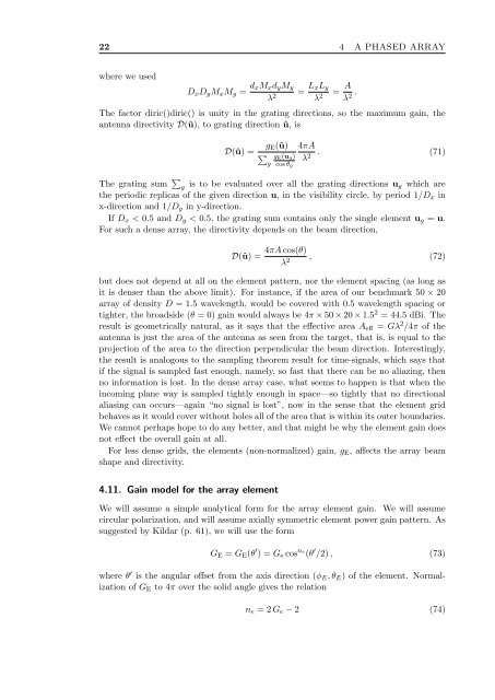
22 4 A PHASED ARRAY<br />
where we used<br />
D x D y M x M y = d xM x d y M y<br />
λ 2<br />
= L xL y<br />
λ 2 = A λ 2 .<br />
The factor diric()diric() is unity in the grating directions, so the maximum gain, the<br />
antenna directivity D(û), to grating direction û, is<br />
D(û) =<br />
g E(û)<br />
∑ g E (u g)<br />
g cos θ g<br />
4πA<br />
λ 2 . (71)<br />
The grating sum ∑ g is to be evaluated over all the grating directions u g which are<br />
the periodic replicas of the given direction u, in the visibility circle, by period 1/D x in<br />
x-direction and 1/D y in y-direction.<br />
If D x < 0.5 and D y < 0.5, the grating sum contains only the single element u g = u.<br />
For such a dense <strong>array</strong>, the directivity depends on the <strong>beam</strong> direction,<br />
D(û) =<br />
4πA cos(θ)<br />
λ 2 , (72)<br />
but does not depend at all on the element pattern, nor the element spacing (as long as<br />
it is denser than the above limit). For instance, if the area of our benchmark 50 × 20<br />
<strong>array</strong> of density D = 1.5 wavelength, would be covered with 0.5 wavelength spacing or<br />
tighter, the broadside (θ = 0) gain would always be 4π × 50 × 20 × 1.5 2 = 44.5 dBi. The<br />
result is geometrically natural, as it says that the effective area A eff = Gλ 2 /4π of the<br />
antenna is just the area of the antenna as seen from the target, that is, is equal to the<br />
projection of the area to the direction perpendicular the <strong>beam</strong> direction. Interestingly,<br />
the result is analogous to the sampling theorem result <strong>for</strong> time-signals, which says that<br />
if the signal is sampled fast enough, namely, so fast that there can be no aliazing, then<br />
no in<strong>for</strong>mation is lost. In the dense <strong>array</strong> case, what seems to happen is that when the<br />
incoming plane way is sampled tightly enough in space—so tightly that no directional<br />
aliasing can occurs—again “no signal is lost”, now in the sense that the element grid<br />
behaves as it would cover without holes all of the area that is within its outer boundaries.<br />
We cannot perhaps hope to do any better, and that might be why the element gain does<br />
not effect the overall gain at all.<br />
For less dense grids, the elements (non-normalized) gain, g E , affects the <strong>array</strong> <strong>beam</strong><br />
<strong>shape</strong> and directivity.<br />
4.11. Gain model <strong>for</strong> the <strong>array</strong> element<br />
We will assume a simple analytical <strong>for</strong>m <strong>for</strong> the <strong>array</strong> element gain. We will assume<br />
circular polarization, and will assume axially symmetric element power gain pattern. As<br />
suggested by Kildar (p. 61), we will use the <strong>for</strong>m<br />
G E = G E (θ ′ ) = G e cos ne (θ ′ /2) , (73)<br />
where θ ′ is the angular offset from the axis direction (φ E , θ E ) of the element. Normalization<br />
of G E to 4π over the solid angle gives the relation<br />
n e = 2 G e − 2 (74)