a Matlab package for phased array beam shape inspection
a Matlab package for phased array beam shape inspection
a Matlab package for phased array beam shape inspection

Create successful ePaper yourself
Turn your PDF publications into a flip-book with our unique Google optimized e-Paper software.
15<br />
“losing sensitivity” (due) to the multiple grating lobes, is unfair. It is unfair in the same<br />
way as it would be unfair to complain that one is losing half of the available receive power<br />
to the re-radiation. The re-radiation is unavoidable by the nature of electromagnetism,<br />
not because of some incompetent engineering.<br />
What the situation would be if we could allow irregular <strong>array</strong>s and non-uni<strong>for</strong>m excitation<br />
fields, I don’t know. For example, people are talking about “superdirective”<br />
<strong>array</strong>s : <strong>for</strong> instance, it is possible to have a linear <strong>array</strong> of isotropic elements where<br />
the gain approaches N 2 , but that requires specifically tailored non-uni<strong>for</strong>m spacing and<br />
specifically tailored excitation fields.<br />
For conventional <strong>array</strong> designs, we need not be overly worried about the grating lobes,<br />
but that does not mean that we should not be somewhat worried about the grating lobes.<br />
The situation with <strong>array</strong>s is actually not too dissimilar from the situation with dishes.<br />
The basic gain pattern, and especially the directivity (maximum gain) of a dish is mainly<br />
determined by the geometric aperture, so that only modest improvements in gain can be<br />
achieved by tailoring the details. For a sizable conventional planar <strong>array</strong>, the directivity<br />
is also largely determined by the geometric area, and can only be improved by so much by<br />
tinkering the details. For <strong>array</strong>s, in order to achieve the naturally available directivity,<br />
we have the extra degree of freedom that we can use fewer elements if the elements<br />
themselves are directive.<br />
There is a prize to that flexibility, or course. The prize is not so much in terms of<br />
directivity, (and hence, not in terms of maximum detection sensitivity), but rather in<br />
terms of directional aliasing. That is, when the gain in the antenna side lobes (grating<br />
lobes or not) is not insignificant, there can be a serious loss of in<strong>for</strong>mation about the<br />
actual target direction. The side lobes can poke all over the sky, and there appears to<br />
be no way to determine via which lobe(s) the observed power came in—unless we know<br />
a priori that there is no scattering coming from the non-intesting lobe directions.<br />
If the large side lobes cannot be suppressed (using directional elements or irregular<br />
element placement), we must in the very least arrange things so that potential targets<br />
in the side lobes are not illuminated by the transmitter. When the reception antenna<br />
is different from the transmission antenna, this should be possible, at least in principle.<br />
But how much does this constrain the available pointing schemes in practice, especially<br />
when using multi-<strong>beam</strong>-<strong>for</strong>ming reception, must be inspected carefully.<br />
Another potential penalty <strong>for</strong> large-gain side lobes is that even if there would be no<br />
illumination in the side lobe directions, unwanted external RF signals may easily sneak<br />
in. On the other hand, the gain is large in only narrow cones, so perhaps this is not such<br />
a serious problem in practice.<br />
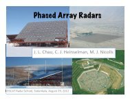
4. A <strong>phased</strong> <strong>array</strong><br />
This section introduces the <strong>phased</strong>-<strong>array</strong> steering- and gain-related concepts, notations<br />
and computations as implemented in the m-files in the e3ant <strong>package</strong>.<br />
4.1. The <strong>array</strong> factor<br />
With reference to Fig. 9, assume that the far-field electric field caused by the antenna<br />
element at the origin, in the direction of unit vector û, is E 0 . Then the far field of<br />
the element at position d m is E m = E 0 e iΨm , where Ψ m is the phase difference of the<br />
two waves when they arrive at the target. This difference corresponds to the distance