Ultrasound Guidance for Vascular Access and Regional Anesthesia
Ultrasound Guidance for Vascular Access and Regional Anesthesia
Ultrasound Guidance for Vascular Access and Regional Anesthesia

You also want an ePaper? Increase the reach of your titles
YUMPU automatically turns print PDFs into web optimized ePapers that Google loves.
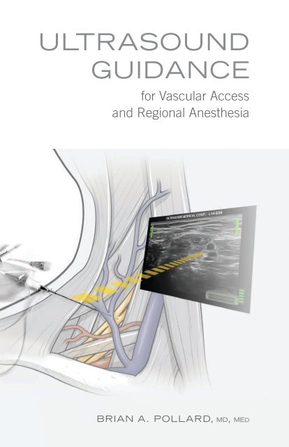
<strong>Ultrasound</strong><br />
<strong>Guidance</strong><br />
<strong>for</strong> <strong>Vascular</strong> <strong>Access</strong><br />
<strong>and</strong> <strong>Regional</strong> <strong>Anesthesia</strong><br />
Brian A. Pollard, md, med
ULTRASOUND<br />
GUIDANCE<br />
<strong>for</strong> <strong>Vascular</strong> <strong>Access</strong><br />
<strong>and</strong> <strong>Regional</strong> <strong>Anesthesia</strong><br />
Brian A. Pollard BSc, MD, MEd, FRCPC<br />
www.usrabook.com<br />
Illustrations by Diana Kryski, MScBMC<br />
www.kryski.com<br />
Book Design <strong>and</strong> Layout by John Beadle<br />
www.john-beadle.com
Library <strong>and</strong> Archives Canada Cataloguing in Publication<br />
<strong>Ultrasound</strong> Imaging <strong>for</strong> <strong>Vascular</strong> <strong>Access</strong> <strong>and</strong> <strong>Regional</strong> <strong>Anesthesia</strong><br />
Brian A. Pollard BSc, MD, MEd, FRCPC<br />
© 2012<br />
All rights reserved. The contents of this book, in whole <strong>and</strong> in part, through any reproduction, are<br />
copyright of Brian A. Pollard, BSc, MD, MEd, FRCPC, <strong>and</strong> Ultrasonix Medical Corporation. The<br />
illustrations in this book, in whole <strong>and</strong> in part, through any reproduction, are copyright of Diana<br />
Kryski, MScBMC. Use in connection with any <strong>for</strong>m of electronic adaptation, computer software, or<br />
by similar or dissimilar methodology now known or hereafter developed is <strong>for</strong>bidden.<br />
The use in this publication of trade names, trademarks, service marks, <strong>and</strong> similar terms, even if<br />
they are not identified as such, is not to be taken as an expression of opinion as to whether or not<br />
they are subject to proprietary rights. While the advice <strong>and</strong> in<strong>for</strong>mation in this book are believed<br />
to be true <strong>and</strong> accurate at the date of going to press, neither the author, Ultrasonix Medical<br />
Corporation, nor the publisher can accept any legal responsibility <strong>for</strong> any errors or omissions that<br />
may be made, <strong>and</strong> make no warranty, express or implied, with respect to the material contained<br />
herein. The author/Ultrasonix Medical Corporation/publisher do not assume any liability <strong>for</strong> injury<br />
<strong>and</strong>/or damage to persons or property arising from this publication. It is the responsibility of the<br />
clinician to determine appropriate practice to ensure patient safety at all times.<br />
ISBN 978-0-9877634-0-2<br />
Design <strong>and</strong> layout by JB Graphics<br />
Printed <strong>and</strong> bound in Toronto, Canada
ULTRASOUND IMAGING<br />
<strong>for</strong> <strong>Vascular</strong> <strong>Access</strong> <strong>and</strong> <strong>Regional</strong> <strong>Anesthesia</strong><br />
SECTION 1<br />
INTRODUCTION TO ULTRASOUND<br />
1 Underst<strong>and</strong>ing <strong>Ultrasound</strong> Physics <strong>for</strong> Clinical Assessment<br />
2 Learning to Scan<br />
3 Principles of Needle Skills<br />
4 Integrating Scanning <strong>and</strong> Needle skills<br />
SECTION 2<br />
ULTRASONIX GPS FOR NEEDLE NAVIGATION<br />
5 Using GPS <strong>for</strong> Needle Navigation In-Plane <strong>and</strong> Out-of-Plane<br />
SECTION 3<br />
ULTRASOUND FOR VASCULAR ACCESS<br />
6 <strong>Ultrasound</strong> Characteristics of Arterial <strong>and</strong> Venous Flow<br />
7 <strong>Ultrasound</strong>-Guided <strong>Vascular</strong> <strong>Access</strong> Line Placement<br />
SECTION 4<br />
ULTRASOUND-GUIDED BLOCKS<br />
8 Femoral Nerve Block<br />
9 Brachial Plexus Blocks<br />
10 Sciatic Nerve Blocks<br />
SECTION 5<br />
ULTRASOUND-ASSISTED BLOCKS<br />
11 Epidural <strong>and</strong> Spinal Blocks<br />
SECTION 6<br />
CONTINUOUS NERVE BLOCK CATHETER TECHNIQUES<br />
12 In-Dwelling Catheters <strong>for</strong> In-Patients <strong>and</strong> Out-Patients<br />
SECTION 7<br />
IMPLEMENTING ULTRASOUND IN THE HOSPITAL SETTING<br />
13 Patient, Surgical, <strong>and</strong> Hospital Expectations
SECTION 1<br />
INTRODUCTION TO ULTRASOUND<br />
Although ultrasound has recently emerged within clinical anesthesia<br />
practice, the routine use of this technology among<br />
anesthesiologists continues to develop in both community <strong>and</strong><br />
academic settings. The introduction of ultrasound techniques<br />
to anesthesia <strong>for</strong> vascular access <strong>and</strong> regional anesthesia is<br />
currently a focus <strong>for</strong> anesthesia education, <strong>and</strong> is paralleled<br />
by a drive <strong>for</strong> technological innovation <strong>and</strong> development among industry leaders.<br />
Ef<strong>for</strong>ts to incorporate ultrasound into anesthetic practice are fundamentally<br />
rooted in the goals of improving patient safety <strong>and</strong> interventional anesthesia<br />
efficacy. Although most anesthesiologists are well aware of the challenges of<br />
vascular access <strong>and</strong> regional anesthesia (<strong>for</strong> both success <strong>and</strong> potential complications),<br />
the introduction of this technology presents novel challenges of acquiring<br />
new knowledge <strong>and</strong> skill sets to achieve these goals.<br />
Consequently, the familiar training adage of “see one, do one, teach one” is<br />
no longer tenable. <strong>Ultrasound</strong> education must provide clinicians with a comprehensive<br />
<strong>and</strong> step-wise approach to underst<strong>and</strong> the fundamentals of the<br />
equipment <strong>and</strong> acquire new skills to suit their unique practice needs <strong>and</strong> setting.<br />
Through an underst<strong>and</strong>ing of this technology at a clinical level, rather than<br />
simply teaching with specific technical agendas or checklists, individuals may<br />
continue to utilize ultrasound to its fullest capacity.<br />
As with acquiring any new skill, there will be initial challenges <strong>for</strong> both the<br />
novice <strong>and</strong> experienced anesthesiologist. From correlating anatomy with sonoanatomy,<br />
<strong>and</strong> visualizing needles <strong>and</strong> fluid dynamics in real-time below the skin<br />
surface, ultrasound provides opportunities <strong>and</strong> unique challenges <strong>for</strong> vascular<br />
access <strong>and</strong> regional anesthesia. As our clinical practice evolves, so will the<br />
expectations placed upon us by patients, surgeons, hospitals, <strong>and</strong> governing<br />
agencies. Achieving the goals of improving patient safety, interventional effi-<br />
ULTRASONIX INTRODUCTION TO ULTRASOUND<br />
1
cacy, <strong>and</strong> overall patient satisfaction will require the learner to set their own<br />
self-directed path towards defining their clinical interests, scope of practice,<br />
<strong>and</strong> skills self- assessment.<br />
The following chapters provide a foundation <strong>for</strong> clinicians to approach, develop,<br />
<strong>and</strong> refine essential knowledge <strong>and</strong> skills to integrate ultrasound into routine<br />
anesthesia practice. By pairing the basic clinical principles of the ultrasound<br />
equipment with the most recent technological innovations in needle guidance,<br />
the goal is to optimize time devoted to reading <strong>and</strong> bench learning to the clinical<br />
setting <strong>and</strong> benefit patient care. This text is designed to provide the basis<br />
from which ongoing, self-directed learning through books, journals, <strong>and</strong> h<strong>and</strong>son<br />
workshops may be facilitated.<br />
Brian A. Pollard<br />
2<br />
ULTRASONIX INTRODUCTION TO ULTRASOUND
CHAPTER 1<br />
Underst<strong>and</strong>ing <strong>Ultrasound</strong> Physics <strong>for</strong> Clinical<br />
Assessment<br />
The ability to acquire, manage, <strong>and</strong> interpret an ultrasound image is a prerequisite<br />
to any other skill set. There<strong>for</strong>e competency with ultrasound imaging must<br />
be achieved prior to interventional procedures. Appreciating the difference<br />
between three-dimensional patient anatomy <strong>and</strong> the two-dimensional screen<br />
image is fundamental <strong>for</strong> ultrasound-guided interventions. Even in the most<br />
limited discussions of ultrasound physics as it relates to our clinical practice,<br />
there are new concepts that present challenges upon first approach.<br />
The <strong>Ultrasound</strong> Transducer – Source of Energy <strong>and</strong> Image<br />
Each ultrasound transducer is required to a) create a source of energy that<br />
when applied to the skin safely penetrates the tissues, <strong>and</strong> b) receive any energy<br />
reflected back to the transducer from the tissues. To generate the ultrasound<br />
energy, an electrical current is applied to the crystal component within<br />
the transducer face. The current is then converted to mechanical (ultrasound)<br />
energy <strong>and</strong> transmitted to the tissues at very high (megahertz) frequencies.<br />
The ultrasound energy produced then travels through the tissues as pulsed,<br />
longitudinal, mechanical waves originating from the point the transducer contacts<br />
the skin.<br />
The transducer (or ‘probe’) is potentially the most limiting component of any<br />
ultrasound scan or subsequent interventional procedure, as it determines<br />
the characteristics of the energy that is emitted, received, <strong>and</strong> subsequently<br />
processed <strong>for</strong> anatomical representation on screen (Fig. 1.1). Underst<strong>and</strong>ing<br />
how this component works is essential, because an inability to optimally select<br />
specific transducer characteristics will result in limited image acquisition, <strong>and</strong><br />
there<strong>for</strong>e potentially impact safety <strong>and</strong> eventual block success.<br />
Resolution<br />
Our ability to ‘visualize’ the anatomy deep to the transducer in contact with the<br />
skin surface is dependent on the potential resolution <strong>for</strong> each scanned area.<br />
Resolution is determined by the extent to which the energy that leaves the<br />
transducer penetrates the tissues <strong>and</strong> returns to the transducer to accurately<br />
ULTRASONIX INTRODUCTION TO ULTRASOUND<br />
3
Fig. 1.1 Schematic illustration of transducer with energy emitted <strong>and</strong> returned through tissues<br />
represent the anatomical structures below. Un<strong>for</strong>tunately, once the vibrational<br />
ultrasound energy leaves the crystalline face of the transducer, it is immediately<br />
<strong>and</strong> progressively degraded as it contacts <strong>and</strong> enters the tissues. This concept<br />
of emitted energy that is ‘lost’ (not returned to the transducer) is known as the<br />
attenuation of ultrasound energy. It can occur through absorption, reflection,<br />
scattering, or refraction of the ultrasound waves (Fig. 1.2). The degree of ultrasound<br />
energy attenuation is directly proportional to the frequency of the energy<br />
emitted <strong>and</strong> the total distance the signal must travel in returning to the transducer<br />
from a structure of interest. This attenuation of the emitted ultrasound<br />
energy may contribute to the distortion or misrepresentation of anatomical relationships<br />
characterized on the ultrasound screen image.<br />
4<br />
ULTRASONIX INTRODUCTION TO ULTRASOUND
Fig. 1.2 Schematic illustration of a) absorption, b) reflection, c) scattering, d) refraction<br />
Even with beam attenuation, it is still possible to visualize anatomical structures<br />
on screen when separated by less than one millimeter. The clinician’s task is<br />
to choose the best transducer <strong>for</strong> each scan, optimize the equipment settings,<br />
<strong>and</strong> remain aware of potential artifacts (<strong>and</strong> pitfalls) due to the attenuation<br />
of ultrasound energy. The physical properties of ultrasound waves travelling<br />
through tissues act not only to reveal anatomical relationships, but also to hide<br />
<strong>and</strong> misrepresent anatomical structures on screen. When examining anatomical<br />
representations on the two dimensional ultrasound screen, our resolution is<br />
determined by the ability to differentiate structures in the ‘X’ (horizontal) <strong>and</strong> ‘Y’<br />
(vertical) axes. In the language of ultrasound imaging, these are described as<br />
Lateral Resolution <strong>and</strong> Axial Resolution respectively (Fig. 1.3).<br />
Lateral Resolution describes the potential to visualize two structures that are<br />
in a plane perpendicular to the direction of the ultrasound beam. This is the<br />
ability to visualize two structures at the same tissue depth relative to the face of<br />
the ultrasound transducer in contact with the skin (appearing ‘side-by-side’ on<br />
screen). Lateral resolution can be improved by increasing either the frequency<br />
ULTRASONIX INTRODUCTION TO ULTRASOUND<br />
5
Fig. 1.3 Schematic illustration of axial <strong>and</strong> lateral resolution <strong>for</strong> discrete objects<br />
or diameter of the ultrasound transducer.<br />
Axial Resolution describes the potential to visualize two structures that are situated<br />
in a plane parallel to the emitted ultrasound beam. These are structures<br />
located at different tissue depths relative to the face of the ultrasound transducer<br />
(one object appears ‘above’ the other on screen). Axial resolution can be<br />
improved by selecting transducers with higher frequencies.<br />
Although both lateral <strong>and</strong> axial resolution are improved with higher frequency<br />
transducers, all ultrasound energy is progressively degraded as it travels further<br />
through tissues. This degree of attenuation (‘loss’) is proportional to the<br />
frequency of the energy applied. Higher frequency energy is ‘lost’ to the tissues<br />
to a greater extent than lower frequency energy with progressive tissue penetration.<br />
Irrespective of frequency, lateral <strong>and</strong> axial resolution always decrease with<br />
increasing tissue depth (Fig. 1.4).<br />
For the lateral <strong>and</strong> axial resolution of superficial structures, ultrasound imaging<br />
should be per<strong>for</strong>med with the highest frequency transducer available. When<br />
6<br />
ULTRASONIX INTRODUCTION TO ULTRASOUND
Fig. 1.4 Schematic illustration of attenuation <strong>for</strong> the same probe at low <strong>and</strong> high frequencies<br />
imaging deep anatomical structures, energy from lower frequency transducers<br />
is less attenuated, potentially allowing more energy to return to the transducer,<br />
<strong>and</strong> generating a better representational image. To optimize the balance of<br />
resolution <strong>and</strong> penetration, select the highest frequency transducer that will<br />
provide the necessary tissue penetration characteristics. The resolution of a<br />
deep structure with a low frequency transducer will not be equivalent to the<br />
resolution of a superficial structure with a high frequency transducer. However,<br />
it will be better than imaging the same structure using a high-frequency<br />
transducer.<br />
Selecting an <strong>Ultrasound</strong> Transducer<br />
Frequency is a key property of each transducer, as it largely determines what<br />
ultrasound screen image representation is possible <strong>for</strong> any given anatomical territory.<br />
In addition to characterization by the Frequency of emitted energy, transducers<br />
are also described by their Array Configuration, <strong>and</strong> their physical Footprint.<br />
With respect to frequency, transducers may be identified by frequency range.<br />
They are broadly categorized as high, mid, <strong>and</strong> low-frequency transducers.<br />
ULTRASONIX INTRODUCTION TO ULTRASOUND<br />
7
Transducers typically characterized as ‘high-frequency’ usually operate above<br />
10 MHz <strong>and</strong> are best suited to visualize structures less than 3 cm from the<br />
surface of the skin. These transducers have excellent resolution <strong>for</strong> shallow<br />
structures. But with increasing depth, structures are less readily visualized due<br />
to attenuation of the emitted <strong>and</strong> returning ultrasound energy. These transducers<br />
are commonly selected <strong>for</strong> examinations of superficial structures such as<br />
the interscalene brachial plexus, peripheral nerves, or superficial vessels.<br />
‘Mid-range’ transducers are typically 5-10 MHz, <strong>and</strong> are used <strong>for</strong> imaging structures<br />
at approximately 3-6 cm below the skin surface. Although these transducers<br />
do not have the potential resolution capabilities of the high-frequency<br />
transducers <strong>for</strong> structures close to the surface, they provide better resolution at<br />
these tissue depths. Mid-range transducers are commonly selected <strong>for</strong> deeper<br />
structures such as imaging of the infraclavicular brachial plexus, sciatic nerve,<br />
or deeper vascular structures.<br />
‘Low frequency’ transducers usually describe those operating below 5 MHz.<br />
They are specifically utilized to provide resolution of structures at even deeper<br />
tissue planes. Although not as commonly used perioperatively as the other<br />
transducers, they are very useful <strong>for</strong> imaging the spine, or in patients presenting<br />
with an increased body mass.<br />
The Array Configuration refers to the arrangement of elements along the face of<br />
the transducer, which can take the <strong>for</strong>m of a linear array or curved array relative<br />
to the scanning surface.<br />
Linear Array transducers are characterized by a narrow series (
Fig. 1.5 Photograph of various linear <strong>and</strong> curved array transducer configurations<br />
This results in a visualized anatomical field that is wider with progressive depth<br />
from the surface. The potential advantage of this curved array configuration is<br />
realized when structures of interest are deep to obstructing superficial anatomy<br />
(such as bone), as the fan-like window allows a wide field at depth from a<br />
narrow window near the skin. These configurations are useful when imaging<br />
around objects such as the clavicle or spinous processes. Although the curved<br />
array transducer has the a<strong>for</strong>ementioned advantage of a wider field of view<br />
relative to transducer footprint, with increasing tissue penetration depth there<br />
is somewhat reduced lateral resolution compared to a linear array transducer<br />
of similar frequency <strong>and</strong> diameter.<br />
The third identifying feature of the transducer taken into clinical consideration<br />
is the Footprint, or diameter of the transducer itself. The footprint of the transducer<br />
is selected to allow optimal scanning <strong>and</strong> needle placement within the<br />
anatomical surface confines of each patient.<br />
The ideal combination of transducer footprint, array configuration, <strong>and</strong> frequency<br />
is based on superficial <strong>and</strong> deep anatomical patient characteristics to<br />
allow <strong>for</strong> acquiring the optimal scan image <strong>and</strong> subsequent needle intervention<br />
(Fig. 1.5).<br />
ULTRASONIX INTRODUCTION TO ULTRASOUND<br />
9
Fig. 1.6 <strong>Ultrasound</strong> image of<br />
shadow beyond bone<br />
Fig. 1.7 <strong>Ultrasound</strong> image of<br />
enhancement artifact<br />
Fig. 1.8 <strong>Ultrasound</strong> image of<br />
reverberation artifact<br />
Artifacts<br />
With an underst<strong>and</strong>ing of the principles of ultrasound physics as it applies to<br />
selecting <strong>and</strong> managing a transducer <strong>for</strong> anatomical visualization, it is important<br />
to address imaging Artifacts that may cause the sonographer to be unaware<br />
of structures that are ‘hidden’, or to ‘perceive’ structures on screen that<br />
do not anatomically exist.<br />
Acoustic Shadowing occurs when structures that are highly attenuating of ultrasound<br />
energy (such as bone) cast a ‘shadow’ immediately deep to the structure<br />
as the ultrasound energy is only partially transmitted through. This is clinically<br />
important because it may falsely appear on the screen image that there are no<br />
anatomical structures located in the area of the ultrasound ‘shadow’ (Fig. 1.6).<br />
The converse phenomenon of Enhancement Artifact occurs when ultrasound energy<br />
passes through a structure that is less attenuating compared to adjacent tissues.<br />
Tissues beyond lower attenuating structures (such as blood vessels) are visually<br />
enhanced due to the relatively greater energy in the signal as it contacts those<br />
surfaces <strong>and</strong> is returned to the transducer. Enhancement artifacts may present the<br />
visual screen representation of a structure that does not exist (Fig. 1.7).<br />
Reverberation Artifact is another common artifact that results from ultrasound<br />
waves striking a surface that is close to perpendicular to the incoming energy.<br />
Each successive ultrasound pulse emitted from the transducer produces a temporal<br />
‘echo’ resulting in a series of parallel lines both above <strong>and</strong> below the actual<br />
object. This is commonly seen with highly attenuating wide-bore needles (Fig. 1.8)<br />
10<br />
ULTRASONIX INTRODUCTION TO ULTRASOUND
Moving Beyond the Transducer<br />
Once the ultrasound energy has been returned to the transducer, it must be<br />
converted to a meaningful visual representation. Although each clinician will<br />
have their own preferences <strong>for</strong> advanced scanning, there are fundamental settings<br />
that must be understood <strong>for</strong> optimal image representation <strong>and</strong> subsequent<br />
procedural interventions. Upon preliminary assessment of an anatomical<br />
field with initial structural identification, screen image optimization requires<br />
control of Depth <strong>and</strong> Gain features.<br />
The selected Depth of the ultrasound screen image <strong>for</strong> viewing should reflect<br />
not only those structures of interest,<br />
but initially must allow <strong>for</strong> a survey of<br />
the wider anatomical field to establish<br />
areas of potential danger with the subsequent<br />
needle interventions (arteries,<br />
veins, <strong>and</strong> pleural spaces). Only after<br />
the field has been surveyed to exclude<br />
areas of concern should the depth be<br />
Fig. 1.9 <strong>Ultrasound</strong> image of field <strong>for</strong> target<br />
<strong>and</strong> adjacent anatomical survey on screen<br />
narrowed to focus on the target <strong>and</strong><br />
adjacent structures. Initial anatomical<br />
scanning should place the objects of<br />
interest between the right <strong>and</strong> left edges<br />
of the screen, <strong>and</strong> with a depth of field that presents the target towards the<br />
bottom of the screen image while still allowing <strong>for</strong> visualization of structures at<br />
slightly greater depths (Fig. 1.9).<br />
In t<strong>and</strong>em with modifications of screen viewing depth, the Gain control is used<br />
to amplify the ultrasound energy returned to the transducer <strong>for</strong> optimization of<br />
grey-scale to delineate structures (Fig. 1.10 a,b,c). It is important to note that<br />
the gain control acts as a <strong>for</strong>m of brightness control to reduce or amplify the already<br />
received signals. This will not change the relative contrast between structures<br />
at the same depth as this is defined by their physical properties. Because<br />
different tissues present different imaging characteristics when translated on<br />
screen, the amount of gain required will vary depending on the absolute <strong>and</strong><br />
relative echogenicity of structures in the field.<br />
ULTRASONIX INTRODUCTION TO ULTRASOUND<br />
11
The strength of the ultrasound energy<br />
returning back to the transducer is<br />
characterized by the brightness of the<br />
image on the screen. This intensity of<br />
returned energy presents an image of<br />
relative echogenicity on the screen.<br />
The tendency <strong>for</strong> a structure to reflect<br />
back to the transducer more emitted<br />
ultrasound energy than those surrounding<br />
structures results in a hyperechoic<br />
structure, which will be whiter<br />
on screen. When a structure has<br />
these characteristics it is echogenic.<br />
In contrast, when a structure reflects<br />
less energy than surrounding structures<br />
it is hypoechoic, with a darker<br />
image on screen. Structures typically<br />
seen as hyperechoic or echogenic<br />
include bone, tendons, pleura, <strong>and</strong><br />
nerves below the clavicles. In contrast,<br />
blood, fluids, <strong>and</strong> nerves above<br />
the clavicles are hypoechoic.<br />
Fig. 1.10 a,b,c <strong>Ultrasound</strong> images showing a)<br />
low, b) medium, c) high gain<br />
12<br />
ULTRASONIX INTRODUCTION TO ULTRASOUND
CHAPTER 2<br />
Learning to Scan<br />
Underst<strong>and</strong>ing how anatomy affects transducer selection, <strong>and</strong> appreciating the<br />
limitations to on screen ‘visualization’ of anatomical structures, the ability to apply<br />
the transducer <strong>and</strong> conduct a thorough assessment is the next step towards<br />
safe <strong>and</strong> effective needle interventions. <strong>Ultrasound</strong> scanning can be defined<br />
by four fundamental transducer movements of sliding, tilting, rotating, <strong>and</strong> angling.<br />
Each of these movements is directed towards exploring the anatomical<br />
field <strong>and</strong> defining the preferred needle trajectories.<br />
Be<strong>for</strong>e scanning, confirm the orientation of the transducer face relative to<br />
screen image. The U symbol in the top left screen corner corresponds to the<br />
palpable ridge on one side of the transducer, which can be confirmed by touching<br />
one side of the transducer face with your finger to see a corresponding<br />
signal change on the screen image. Here is a useful step to provide a relative<br />
spatial connection between the two-dimensional screen image <strong>and</strong> the threedimensional<br />
scanning plane: orient the transducer such that the left <strong>and</strong> right<br />
sides are consistent with the left <strong>and</strong> right sides of the ultrasound screen, <strong>and</strong><br />
position the plane of the screen similar to the plane of the transducer (Fig. 2.1)<br />
Descriptively, transducer application to the skin is usually with respect to surface<br />
anatomy body planes (i.e. transverse), whereas transducer motion is generally in<br />
reference to anatomical target structures. Application of the transducer in relation<br />
to surface anatomy reflects an initial attempt to visualize deep structures in crosssection<br />
based on knowledge of underlying anatomical relationships. Once the<br />
transducer is applied, the sliding, tilting, rotating, <strong>and</strong> angling of the transducer is<br />
used to optimize the image of the anatomical structure of interest.<br />
An initial ultrasound survey of the anatomical field to identify l<strong>and</strong>marks is made<br />
with a transverse <strong>and</strong> longitudinal sliding motion over the superficial structures<br />
of interest (Fig. 2.2 a,b). Once the field has been preliminarily scanned <strong>for</strong> local<br />
anatomical relationships, a more detailed exam using a longitudinal sliding<br />
motion is used to define <strong>and</strong> confirm position <strong>and</strong> trajectory of structures. Having<br />
visualized a structure in cross-section through it’s longitudinal course, the<br />
clinician can identify the point at which it is most easily distinguishable <strong>and</strong><br />
accessible <strong>for</strong> eventual needle intervention.<br />
ULTRASONIX INTRODUCTION TO ULTRASOUND<br />
13
Fig. 2.1 Photograph illustrating corresponding planes of transducer <strong>and</strong> screen relative to patient<br />
14<br />
ULTRASONIX INTRODUCTION TO ULTRASOUND
Fig. 2.2 a,b Photographs of a) longitudinal <strong>and</strong> b) transverse sliding motions over femoral nerve<br />
The obtained transverse image of anatomical structures is also referred to as a<br />
short-axis view. Although the transducer may be in a relative transverse position<br />
from the initial application to skin, the subsequent tilting, rotating, <strong>and</strong> angling<br />
of the transducer are subtle movements aimed at refinement of the ultrasound<br />
image (Fig. 2.3 a,b,c).<br />
Fig. 2.3 a,b,c Photographs illustrating a) tilting, b) rotating, <strong>and</strong> c) angling over femoral nerve<br />
Tilting the transducer makes use of the physical properties of ultrasound energy<br />
to improve visualization of a structure with outgoing ultrasound waves contacting<br />
the structure as close to perpendicular as possible. As the incident angle of<br />
emitted energy approaches 90 degrees the intensity of reflected signals will increase<br />
<strong>and</strong> should provide a more distinct ultrasound image (Fig. 2.4 a,b). This<br />
change in reflected signal with a transition towards perpendicular incidence of<br />
emitted ultrasound energy is know as anisotropy.<br />
The transducer movement of rotation is used to move from the short-axis representation<br />
of structures towards a longitudinal image with rotation through a<br />
full 90 degrees to achieve a long-axis view (Fig. 2.5 a,b).<br />
The motion of transducer angling utilizes gentle pressure on one side of the<br />
transducer to direct the path of emitted energy at an angle not perpendicular to<br />
ULTRASONIX INTRODUCTION TO ULTRASOUND<br />
15
Fig. 2.4 a,b <strong>Ultrasound</strong> images of median nerve demonstrating anisotropy<br />
Fig. 2.5 a,b <strong>Ultrasound</strong> images of blood vessel in a) short <strong>and</strong> b) long-axis views<br />
the resting contour of the skin surface. Gentle pressure may be applied to one<br />
side of the transducer to maintain full contact along the skin surface in concave<br />
or confined fields, or when attempting to direct the beam under a superficial<br />
highly attenuating structure such as bone. If angling is not adequate to maintain<br />
skin contact or visualize past obstructions, a smaller footprint or curved<br />
array transducer should be selected.<br />
<strong>Ultrasound</strong> scanning will be per<strong>for</strong>med with left or right h<strong>and</strong>s depending on<br />
the anatomical location of the structures of interest. Only after demonstrating<br />
the ability to effectively scan with both h<strong>and</strong>s should needle techniques be<br />
introduced as part of the progression towards safe <strong>and</strong> effective ultrasoundbased<br />
vascular access <strong>and</strong> regional anesthesia practice.<br />
16<br />
ULTRASONIX INTRODUCTION TO ULTRASOUND
CHAPTER 3<br />
Principles of Needle Skills<br />
Knowledge of ultrasound physics as it relates to equipment selection <strong>and</strong> image<br />
management <strong>for</strong> coherent ultrasound visualization is a prerequisite <strong>for</strong> acquiring<br />
the additional skill of directing interventional needles under ultrasound<br />
guidance.<br />
Once a target structure has been optimally represented on screen in shortaxis<br />
view, the transducer position should remain relatively unchanged <strong>for</strong> the<br />
remainder of the procedure. If the ideal ultrasound target image has been<br />
achieved, moving the transducer to find the needle only takes you further away<br />
from your anatomical goal. The needle should always be brought to the transducer<br />
beam plane, rather than the beam plane chasing the needle.<br />
Transducer orientation is characterized as transverse <strong>and</strong> longitudinal in reference<br />
to the physical body planes (cross-sectional, parasagittal), <strong>and</strong> in relation<br />
to the ultrasound appearance of anatomical structures (short-axis, long-axis).<br />
Both the short axis <strong>and</strong> long axis ultrasound images are useful to correctly identify<br />
<strong>and</strong> differentiate anatomical structures in the field of view. However, with the<br />
introduction of needle techniques, there must be an additional characterization<br />
of the plane in which the needle is introduced relative to the ultrasound beam.<br />
When needles are introduced to the visualized ultrasound field, they are described<br />
as being In-Plane or Out-of-Plane with the ultrasound beam.<br />
With the In-Plane (IP) needle technique, the needle is followed in real time from<br />
penetration of skin surface to deep anatomical target in the line of ultrasound<br />
beam plane visualization (Fig. 3.1 a,b). This has the advantage of constant visualization<br />
during advancement of the needle to minimize any aberrant needle<br />
direction <strong>and</strong> potential trauma to nearby structures. However, the conventional<br />
In-Plane approach requires refined technical skills to keep the needle within<br />
the sub-millimetre width of the ultrasound beam along its trajectory. This becomes<br />
increasingly difficult with the use of smaller diameter needles <strong>and</strong> with<br />
deeper target structures.<br />
ULTRASONIX INTRODUCTION TO ULTRASOUND<br />
17
Fig. 3.1 a,b Photograph <strong>and</strong> ultrasound image of Tuohy needle <strong>and</strong> tofu model with In-Plane<br />
(IP) needle orientation<br />
In contrast, the Out-of-Plane (OOP) needle approach does not allow <strong>for</strong> continual<br />
visualization of the needle as it passes through the tissues, but rather<br />
only as it passes through the thin anatomical plane of the transducer beam represented<br />
on-screen (Fig. 3.2 a,b). The Out-of-Plane technique conventionally<br />
does not indicate the relationship of the needle to anatomic structures either<br />
be<strong>for</strong>e or after it crosses the beam.<br />
Fig. 3.2 a,b Photograph <strong>and</strong> ultrasound image of Tuohy needle <strong>and</strong> tofu model with Out-of-<br />
Plane (OOP) needle orientation<br />
18<br />
ULTRASONIX INTRODUCTION TO ULTRASOUND
CHAPTER 4<br />
Integrating Scanning <strong>and</strong> Needle skills<br />
Learning fundamental scanning skills in the clinical setting is ideal because it<br />
offers the ‘true’ anatomical environment, <strong>and</strong> should not present any risk to<br />
the individuals being scanned, even with novice learners. However, with the<br />
potential <strong>for</strong> tissue injury in acquiring needle skills, a lower fidelity setting is required.<br />
There are many commercial <strong>and</strong> h<strong>and</strong>-made models that can facilitate<br />
the acquisition of needling skills prior to entering the clinical setting. Whatever<br />
model is selected, it should allow <strong>for</strong> skill acquisition to progress from basic to<br />
advanced needle to target imaging.<br />
The shift from learning with a low fidelity model to the clinical setting requires<br />
the successful integration of ultrasound scanning <strong>and</strong> needle skills into one<br />
coherent activity. Although providing technical parallels to needle guidance<br />
in tissue, these models are not able to demonstrate the dynamic, real time<br />
perception of injected fluids, or soft tissue movement that contribute to the<br />
high fidelity environment of the clinical setting. Once proficient with needle<br />
techniques in the model setting, cautious advancement to clinical application<br />
is required. Clinical attention to paresthesias, resistance or pain with injection,<br />
careful aspiration, <strong>and</strong> visual confirmation of needle location <strong>and</strong> spread of local<br />
anesthetics temporally with injection will improve procedural outcomes <strong>and</strong><br />
minimize patient risks.<br />
Another prerequisite to success with ultrasound-guided procedures is patient<br />
education to set expectations <strong>and</strong> minimize anxiety. After in<strong>for</strong>med discussion,<br />
the judicious use of intravenous benzodiazepine sedation in the monitored setting<br />
may also enhance patient satisfaction <strong>and</strong> reduce pharmacologic sensitivities<br />
to local anesthetics.<br />
Needle Skills <strong>for</strong> <strong>Vascular</strong> <strong>Access</strong><br />
For learning both ultrasound-guided vascular access <strong>and</strong> regional anesthesia<br />
needle skills, a readily constructed tofu model will be demonstrated. For vascular<br />
access, equipment required will include a block of extra-firm tofu, small<br />
diameter flexible tubing (i.e. 3/8” latex tubing) to act as ‘vessel’, wood dowel<br />
to introduce the attached tubing through the tofu, stopcocks, <strong>and</strong> ties at either<br />
end <strong>for</strong> water-tight securing of the tubing <strong>and</strong> a 20cc syringe to create pres-<br />
ULTRASONIX INTRODUCTION TO ULTRASOUND<br />
19
sure <strong>for</strong> arterial simulation in one tube.<br />
The equipment <strong>and</strong> design is shown in<br />
Fig. 4.1.<br />
Fig. 4.1 Photograph of simple ‘vascular’ tofu<br />
model <strong>and</strong> required equipment<br />
With the model prepared, both tubes<br />
are completely filled with water <strong>and</strong><br />
the syringe remains attached to one<br />
stopcock to simulate arterial flow on<br />
ultrasound scanning through rhythmic<br />
plunger compression. Familiarization<br />
with Doppler imaging <strong>and</strong> assessment<br />
of arterial <strong>and</strong> venous flow characteristics should be per<strong>for</strong>med on the model.<br />
With initial scanning, the model ‘vessels’ can be visualized in short <strong>and</strong> long<br />
axis views (Fig. 4.2).<br />
Visualizing both ‘vessels’ in short axis, with rhythmic compression of the syringe,<br />
the application of colour Doppler or colour Power Doppler will demon-<br />
Fig. 4.2 <strong>Ultrasound</strong> image of ‘vessel’ in a) short axis <strong>and</strong> b) long axis<br />
Fig. 4.3 <strong>Ultrasound</strong> image of 2 ‘vessels’ with<br />
colour Doppler applied<br />
Fig. 4.4 <strong>Ultrasound</strong> image of 2 vessels with<br />
wave<strong>for</strong>m Doppler applied<br />
20<br />
ULTRASONIX INTRODUCTION TO ULTRASOUND
strate flow differentially in the simulated arterial vessel (Fig. 4.3). Further definitive<br />
‘vessel’ characterization is then completed with the addition of wave<strong>for</strong>m<br />
Doppler assessment (Fig. 4.4).<br />
Maintaining the transducer in short axis <strong>for</strong> an Out-of-Plane (OOP) approach<br />
to vascular access, or rotating through 90 degrees to achieve a long axis view<br />
<strong>for</strong> an In-Plane (IP) approach, vascular catheter placement may then be per<strong>for</strong>med<br />
(Fig. 4.5 a,b).<br />
Fig. 4.5a Photograph of probe <strong>and</strong> vascular<br />
needle In-Plane with vessel tubing<br />
Fig. 4.5b <strong>Ultrasound</strong> image of In-Plane<br />
guidewire <strong>and</strong> needle in ‘vessel’<br />
Needle Skills <strong>for</strong> <strong>Regional</strong> <strong>Anesthesia</strong><br />
The tofu model <strong>for</strong> regional anesthesia needle skill acquisition requires a block of<br />
extra-firm tofu, small (~2mm) <strong>and</strong> large (~8mm) wood dowel <strong>for</strong> hypoechoic targets,<br />
<strong>and</strong> similar diameter wire <strong>for</strong> creating small <strong>and</strong> large hyperechoic targets.<br />
Beginner level models are created by gently directing the large wood <strong>and</strong> wire<br />
‘targets’ through the tofu, orienting them perpendicular to the surface planes.<br />
Fig. 4.6a Photograph of ‘easy’ tofu model<br />
with In-Plane Tuohy needle to large wood target<br />
Fig. 4.6b <strong>Ultrasound</strong> image of In-Plane<br />
Tuohy needle to large hypoechoic wood target<br />
ULTRASONIX INTRODUCTION TO ULTRASOUND<br />
21
Using the large targets <strong>and</strong> large diameter<br />
needles (such as a Tuohy) <strong>for</strong> easier<br />
visualization facilitates initial needle<br />
to target practice (Fig. 4.6 a,b).<br />
After demonstrating the ability to reliably<br />
maintain the needle In-Plane<br />
along the entire course from surface<br />
to target with both h<strong>and</strong>s, the model<br />
may be used <strong>for</strong> progressively more<br />
challenging tasks. Targets may next be<br />
Fig. 4.7 Photograph of ‘complex’ tofu model<br />
with small diameter targets <strong>and</strong> block needle<br />
presented in the same spatial orientation within the model but with smaller<br />
diameters, <strong>and</strong> then as small diameter targets with oblique trajectories relative<br />
to surface planes (Fig. 4.7). As final increments of complexity, the size of needle<br />
used is reduced from the Tuohy to conventional block needles, <strong>and</strong> targets may<br />
be reduced in length <strong>and</strong> completely embedded within the model so that there<br />
are no physical cues as to echogenicity, size, or location.<br />
This low fidelity model will allow self-assessment of both scanning <strong>and</strong> needle<br />
skills from visualization <strong>and</strong> the tactile feedback of the needle contacting the<br />
target. With each desired increase in model complexity, transition using sequentially<br />
smaller target <strong>and</strong> needle diameters.<br />
22<br />
ULTRASONIX INTRODUCTION TO ULTRASOUND
SECTION 2<br />
ULTRASONIX GPS FOR NEEDLE NAVIGATION<br />
The previous chapter addressed some of the technical challenges of integrating<br />
ultrasound scanning <strong>and</strong> needle skills. An inability to identify the needle tip<br />
as it passes through the tissues may reduce the potential benefits when using<br />
ultrasound <strong>for</strong> vascular access or regional anesthesia. Needle tip visualization is<br />
a key clinical focus when integrating ultrasound <strong>and</strong> needle skills into practice.<br />
CHAPTER 5<br />
Using GPS <strong>for</strong> Needle Navigation In-Plane <strong>and</strong> Out-of-Plane<br />
Identifying the location of the needle tip can be challenging <strong>for</strong> both the In-<br />
Plane <strong>and</strong> Out-of-Plane ultrasound-guided needle techniques. There may be<br />
difficulties in maintaining visualization of the needle along it’s entire length<br />
when In-Plane. There can be uncertainty in the Out-of-Plane technique when<br />
the needle tip may have passed beyond the thin ultrasound beam image <strong>and</strong><br />
only part of the shaft is being represented on screen (Figs. 5.1, 5.2).<br />
Fig. 5.1a,b Photograph <strong>and</strong> ultrasound image of In-Plane needle orientation with tip projecting<br />
distal to needle visualized on screen<br />
ULTRASONIX GPS FOR NEEDLE NAVIGATION<br />
23
Fig. 5.2a,b Photograph <strong>and</strong> ultrasound image of Out-of-Plane needle orientation with tip<br />
projecting beyond ultrasound beam plane<br />
The introduction of Ultrasonix GPS technology to assist in visual needle navigation<br />
<strong>for</strong> vascular access <strong>and</strong> regional anesthesia allows the path of the needle to<br />
be projected on screen even be<strong>for</strong>e the needle enters the tissues. Using magnetic<br />
energy that is integrated with the needle <strong>and</strong> ultrasound screen image,<br />
the orientation of the needle at the skin surface as directed by the clinician’s<br />
h<strong>and</strong> allows a virtual path towards the target to be projected on the ultrasound<br />
screen. This screen ‘path’ represents the actual needle trajectory that would be<br />
followed if the needle were to enter the skin with that three-dimensional orientation.<br />
The clinician is now able to ‘virtually’ direct their needle towards a vascular<br />
or neural target with real-time modifications of direction to ensure the needle<br />
is travelling along the desired course, using either the In-Plane or Out-of-Plane<br />
technique. With this virtual needle trajectory projected on screen, needle to<br />
target localization is facilitated <strong>for</strong> the novice <strong>and</strong> skilled clinician alike. The<br />
likely result is fewer needle manipulations in the tissues to achieve the desired<br />
clinical outcome.<br />
In-Plane GPS Needle Navigation<br />
One of the principal challenges of the In-Plane ultrasound needle technique<br />
is maintaining visualization of the needle along its entire trajectory from the<br />
point of entering the skin to desired target. This often requires adjustments to<br />
the previously optimized ultrasound probe orientation that may permit needle<br />
visualization, but with less than ideal anatomical imaging. GPS needle navigation<br />
allows the clinician to orient the needle In-Plane from the point of contact<br />
with the skin (at one edge of the transducer) to the desired target (across the<br />
length of the transducer face) without movement, once anatomical goals have<br />
been established.<br />
24<br />
ULTRASONIX GPS FOR NEEDLE NAVIGATION
Fig. 5.3 <strong>Ultrasound</strong> screen image<br />
demonstrating Orientation Bar locations.<br />
Following optimization of anatomical<br />
target image, the needle is oriented in<br />
the usual In-Plane fashion along what<br />
is perceived to be the middle of the<br />
long axis of the transducer. To assist in<br />
this spatial orientation of needle with<br />
transducer, the GPS needle navigation<br />
system utilizes In-Plane Orientation<br />
Bars to highlight the correct three- dimensional<br />
needle <strong>and</strong> h<strong>and</strong> position.<br />
These Orientation Bars are located on<br />
the left <strong>and</strong> right side of the ultrasound<br />
screen image field (Fig. 5.3).<br />
The objective when using the In-Plane<br />
GPS technique is to achieve ‘green’<br />
indicator Orientation Bars on both the<br />
proximal edge of the transducer (where<br />
the needle is introduced), <strong>and</strong> the distal<br />
edge of the transducer (where the<br />
target is located), by h<strong>and</strong> orientation<br />
prior to needle penetration of skin. The<br />
first task is to orient the needle along<br />
the perceived middle of the long axis of<br />
the transducer at the edge where the<br />
needle will initially contact the skin surface.<br />
As the needle emerges In-Plane,<br />
the colour of the Orientation Bar on the<br />
corresponding side of the ultrasound<br />
screen will transition from red, to yellow,<br />
to green (Fig. 5.4 a,b,c).<br />
Fig. 5.4a,b,c Orientation Bar transition with<br />
correct In-Plane needle position<br />
Assistance with In-Plane alignment of<br />
the needle along the entire transducer<br />
is initially aided through the ‘Face’ Orientation<br />
Bar in the lower right corner of<br />
the screen that projects a face-on view<br />
of the needle <strong>and</strong> contact surface of<br />
ULTRASONIX GPS FOR NEEDLE NAVIGATION<br />
25
Fig. 5.5a,b ‘Face’ Orientation Bar showing needle position in dotted line <strong>and</strong> colour transition<br />
from white to green with progression towards In-Plane needle orientation<br />
the transducer. Rather than only visually attempting to determine the midline<br />
of the transducer, this Face Orientation Bar projects the position of the needle<br />
in relation to the midline with a similar transition from white to green with increasing<br />
orientation towards an In-Plane trajectory (Fig. 5.5 a,b). This provides<br />
direction <strong>for</strong> preliminary orientation of the needle that is then refined with the<br />
aid of Orientation Bars on the left <strong>and</strong> right side of the screen during real-time<br />
imaging <strong>and</strong> needle introduction.<br />
Fig. 5.6 Green Orientation Bars <strong>for</strong> correct<br />
In-Plane needle position with needle<br />
trajectory projected to target<br />
Once the proximal needle edge is established<br />
as In-Plane with a green Orientation<br />
Bar, subsequent h<strong>and</strong> movements<br />
allow the trajectory to be refined<br />
along the entire length of the ultrasound<br />
beam as the Indicator Bar on<br />
the distal side of the transducer transitions<br />
from red, to yellow, to green. With<br />
the needle In-Plane along the length of<br />
the transducer, all three screen Orientation<br />
Bars will be green, <strong>and</strong> the virtual<br />
needle projected on screen may<br />
be directed towards the appropriate target depth by the clinician elevating or<br />
lowering their h<strong>and</strong> (Fig. 5.6).<br />
26<br />
ULTRASONIX GPS FOR NEEDLE NAVIGATION
Fig. 5.7 Out-of-Plane ultrasound image with<br />
red Target Indicator circle highlighting vessel<br />
target position<br />
Fig. 5.8 Out-of-Plane ultrasound image with<br />
green Target Indicator as needle reaches<br />
beam plane<br />
Out-of-Plane GPS Needle Navigation<br />
In contrast to the In-Plane technique, the Out-of-Plane technique allows <strong>for</strong><br />
the desired needle tip placement to be achieved from any orientation of needle<br />
relative the to the ultrasound probe at the skin surface. Although the same<br />
considerations remain <strong>for</strong> conventional Out-of-Plane techniques, the addition<br />
of GPS needle navigation overcomes one major drawback <strong>for</strong> Out-of-Plane needles<br />
- the final needle tip position can be localized definitively within the beam<br />
plane at the desired target location.<br />
As with the In-Plane technique, the optimal anatomical site <strong>for</strong> intervention<br />
must be identified be<strong>for</strong>e any needle intervention is considered. With GPS<br />
needle navigation engaged <strong>and</strong> the needle in proximity to the skin surface, the<br />
virtual trajectory at which point the needle tip would cross the ultrasound beam<br />
is visualized on screen as a red Target Indicator circle (Fig. 5.7).<br />
Using this technique, the red Target Indicator circle may be translated to different<br />
horizontal <strong>and</strong> vertical locations at the beam plane on screen by the<br />
three-dimensional h<strong>and</strong> movements of the clinician. With the Target Indicator<br />
positioned at the desired anatomical location, as the needle reaches the beam<br />
plane, the Target Indicator colour changes from red to green to indicate that the<br />
needle tip is at the beam plane (Fig. 5.8). As long as the tip is maintained at the<br />
beam plane, the Indicator remains green, <strong>and</strong> will revert back to red should the<br />
needle move proximal or distal out of the beam plane. This warning avoids the<br />
common concern with the conventional Out-of-Plane technique, whereby the<br />
tip of the needle projects beyond the plane of the ultrasound beam, <strong>and</strong> only<br />
the shaft is perceived on screen.<br />
ULTRASONIX GPS FOR NEEDLE NAVIGATION<br />
27
SECTION 3<br />
ULTRASOUND FOR VASCULAR ACCESS<br />
The ability to obtain vascular access <strong>for</strong> assessment <strong>and</strong> intervention is one of<br />
the anesthesiologist’s defining skill sets. Increasingly, there has been an interest,<br />
<strong>and</strong> in some regions a m<strong>and</strong>ate, to move beyond superficial l<strong>and</strong>marks<br />
<strong>and</strong> anticipated anatomical relationships <strong>for</strong> percutaneous venous <strong>and</strong> arterial<br />
cannulation. The addition of ultrasound technology not only facilitates vascular<br />
access <strong>for</strong> all levels of practice. It also illustrates why these typically routine<br />
procedures can on occasion become surprisingly challenging as anatomical<br />
variability is made readily apparent.<br />
The ultrasound-guided approach to vascular access is based on the same fundamental<br />
anatomical knowledge <strong>and</strong> sterile percutaneous approach as conventional<br />
practice. However, the use of ultrasound <strong>and</strong> GPS needle navigation<br />
under real-time visualization, in place of the conventional ‘blind’ technique with<br />
the endpoint of needle aspiration <strong>for</strong> a blood-filled syringe, does require slight<br />
procedural modifications. This chapter demonstrates the approach to real-time<br />
ultrasound imaging with the addition of GPS needle navigation technology <strong>for</strong><br />
vascular access using the internal jugular vein as an illustration.<br />
CHAPTER 6<br />
<strong>Ultrasound</strong> Characteristics of Arterial <strong>and</strong> Venous Flow<br />
For vascular access, arteries <strong>and</strong> veins are conventionally approached from<br />
their anticipated anatomical relationships with surface l<strong>and</strong>marks. This principle<br />
remains relatively unchanged in the ultrasound-guided approach. Typical<br />
cues such as the visual tissue distension <strong>for</strong> veins or the tactile pulsatility of arteries<br />
still guide our application of transducer to skin. However, from this point<br />
28<br />
ULTRASONIX ULTRASOUND FOR VASCULAR ACCESS
Fig. 6.1a,b <strong>Ultrasound</strong> screen image showing same vessel with both red <strong>and</strong> blue Doppler signal<br />
onwards it is the characteristics of veins <strong>and</strong> arteries on ultrasound that guide<br />
our needle placement <strong>for</strong> safe <strong>and</strong> effective vascular access.<br />
Using the basics of ultrasound scanning <strong>and</strong> image management previously<br />
established, the focus shall now be on the specifics of ultrasound imaging as<br />
it relates to the identification of vascular structures <strong>and</strong> needle access. In addition<br />
to using depth <strong>and</strong> gain controls <strong>for</strong> image optimization, the Doppler<br />
capability is essential to distinguish hypoechoic structures as vascular vs. nonvascular<br />
be<strong>for</strong>e introducing needles to the field.<br />
With Doppler imaging of blood vessels, the flow of blood towards or away from<br />
the transducer results in a screen image that differentiates blood flow from the<br />
rest of the ‘static’ tissues by assigning colour to the area of flow within the vessel.<br />
The ultrasound energy emitted will be returned to the transducer at a different<br />
frequency depending whether it encounters blood flow towards or away<br />
from the source energy. This is known as the Doppler shift in frequency. Blood<br />
flow moving towards the ultrasound source reflects energy at a relatively higher<br />
frequency (positive Doppler shift), <strong>and</strong> at a relatively lower frequency (negative<br />
Doppler shift) when flow is away from the transducer. In Colour Doppler mode,<br />
any blood flow towards the transducer will be red on screen, <strong>and</strong> flow away<br />
from the transducer will be blue on screen. It must be emphasized that colour<br />
does not necessarily characterize arterial or venous flow. Depending on the<br />
angle of the transducer placement on the skin relative to flow, arteries or veins<br />
may each be represented as red or blue (Fig. 6.1 a,b).<br />
If there is no colour signal from a suspected blood vessel (no Doppler shift), the<br />
structure being assessed may not be vascular, may not have any flow within it<br />
ULTRASONIX ULTRASOUND FOR VASCULAR ACCESS<br />
29
Fig. 6.2a,b <strong>Ultrasound</strong> image of same vessel with ‘no flow’ <strong>and</strong> flow depending on angle of probe<br />
(as is the case with a thrombosed vessel), or the transducer may be oriented<br />
perpendicular to the flow <strong>and</strong> is there<strong>for</strong>e not being detected. For this latter<br />
reason careful ultrasound assessment of every field must be made using all<br />
transducer motions to avoid a false-negative vascular assessment (Fig. 6.2 a,b).<br />
In addition to Colour Doppler mode, there is the feature of Colour Power Doppler.<br />
This mode offers the advantage of detecting very slow flow, <strong>and</strong> is largely independent<br />
of incident beam angle (detection of flow even when the emitted ultrasound<br />
beam is near perpendicular to the vessel). The Colour Power Doppler function is<br />
a more sensitive indicator of vascular flow <strong>and</strong> is there<strong>for</strong>e often useful as a scout<br />
scan be<strong>for</strong>e defining venous or arterial characteristics (Fig. 6.3 a,b). However, Colour<br />
Power Doppler mode does not provide any in<strong>for</strong>mation about the direction of<br />
flow relative to the transducer as there is no red-blue colour differentiation<br />
Although Colour Doppler <strong>and</strong> Colour Power Doppler may be used to detect<br />
blood flow following assessment based on anatomical location, vessel shape,<br />
pulsatility, <strong>and</strong> compressibility, neither of these modes is adequate to defini-<br />
Fig. 6.3a,b <strong>Ultrasound</strong> of same vessel without, <strong>and</strong> with application of CPD<br />
30<br />
ULTRASONIX ULTRASOUND FOR VASCULAR ACCESS
Fig. 6.4 <strong>Ultrasound</strong> image of spectral Doppler<br />
wave<strong>for</strong>ms <strong>for</strong> arterial (a) <strong>and</strong> venous (b) flow<br />
tively characterize blood flow as arterial<br />
or venous. Following recognition of<br />
flow through Colour Doppler or Colour<br />
Power Doppler examination, Spectral<br />
Doppler Wave<strong>for</strong>m examination is required<br />
to definitively characterize the<br />
vessel as arterial or venous. The Spectral<br />
Doppler wave<strong>for</strong>m characteristics<br />
of arteries <strong>and</strong> veins are depicted in<br />
Fig. 6.4.<br />
ULTRASONIX ULTRASOUND FOR VASCULAR ACCESS<br />
31
CHAPTER 7<br />
<strong>Ultrasound</strong>-Guided <strong>Vascular</strong> <strong>Access</strong> Line Placement<br />
Internal Jugular Vein <strong>Vascular</strong> <strong>Access</strong><br />
Anesthesiologists frequently select the Internal Jugular Vein (IJV) <strong>for</strong> central<br />
vascular access because its anatomical position relative to surface <strong>and</strong> deep<br />
structures is well established. Based on this familiarity, the IJV will be utilized to<br />
demonstrate the addition of ultrasound imaging <strong>for</strong> venous vascular access. Arterial<br />
catheter placement follows a similar methodology to that described here<br />
described <strong>for</strong> the IJV.<br />
On ultrasound short-axis imaging the IJV appears as a hypoechoic structure<br />
that is typically slightly irregular in shape, <strong>and</strong> lies lateral to the smaller <strong>and</strong><br />
rounder carotid artery in the neck. There are many hypoechoic round structures<br />
in this field (including the nerves of the brachial plexus), <strong>and</strong> both carotid<br />
artery <strong>and</strong> IJV are frequently pulsatile. There<strong>for</strong>e, definitive identification of this<br />
structure requires Colour Doppler or Colour Power Doppler assessment to identify<br />
characteristics of flow, <strong>and</strong> then further distinction between artery <strong>and</strong> vein<br />
using Spectral Wave<strong>for</strong>m analysis.<br />
Known anatomical surface relationships <strong>and</strong> fundamental scanning techniques<br />
allow the transducer to be transversely oriented over the anticipated IJV territory<br />
of the neck. Initial ‘scout’ scans will reveal the sternocleidomastoid superficially,<br />
<strong>and</strong> two deeper hypoechoic structures of varying diameter, shape, compressibility,<br />
<strong>and</strong> pulsatility. Using Doppler techniques the anatomical position of<br />
the carotid artery <strong>and</strong> IJV are identified on the ultrasound screen image. With<br />
a confirmed identification of carotid artery<br />
<strong>and</strong> IJV, the IJV is optimally visualized<br />
in the centre of the screen <strong>and</strong><br />
then may be approached using either<br />
an In-Plane or Out-of-Plane needle<br />
technique (Fig. 7.1).<br />
Fig. 7.1 <strong>Ultrasound</strong> showing centred IJV<br />
wave<strong>for</strong>m<br />
The In-Plane vascular access approach<br />
to the IJV requires a longitudinal<br />
view of the vessel. Once clearly<br />
establishing the IJV in short axis, rotate<br />
32<br />
ULTRASONIX ULTRASOUND FOR VASCULAR ACCESS
Fig. 7.2 Photograph illustrating probe <strong>and</strong> needle position <strong>for</strong> In-Plane (IP) IJV access<br />
ULTRASONIX ULTRASOUND FOR VASCULAR ACCESS<br />
33
Fig. 7.3 <strong>Ultrasound</strong> projection of needle with<br />
correct IP orientation <strong>and</strong> trajectory to IJV<br />
Fig. 7.4 <strong>Ultrasound</strong> long-axis view of IJV with<br />
needle <strong>and</strong> guidewire in vessel<br />
the transducer through 90 degrees to capture the vein in long axis (be careful<br />
not to lose the vessel in the field of view). If the vessel image is lost, return to<br />
the short axis view <strong>for</strong> confirmation once again be<strong>for</strong>e rotating to the long-axis<br />
view. Note that it may be difficult to capture colour Doppler or Spectral Wave<strong>for</strong>m<br />
Doppler analysis in the long axis view because the transducer often rests<br />
perpendicular to the flow of blood. With the optimal ultrasound image of the<br />
defined vessel achieved, engage the GPS function to enable needle navigation<br />
<strong>and</strong> bring the vascular access needle to rest on the skin (Fig. 7.2).<br />
When the needle is correctly In-Plane <strong>and</strong> all three Orientation Bars on the<br />
screen image are illuminated in green, define the vertical needle trajectory as desired<br />
on screen by elevating or lowering the needle in h<strong>and</strong> (Fig. 7.3). At this point<br />
introduce the needle under direct visualization towards the centre of the IJV.<br />
With the needle held securely <strong>and</strong> tip In-Plane within the vessel, the probe is<br />
placed on the sterile field, <strong>and</strong> the sensing introducer is removed with the free<br />
h<strong>and</strong> <strong>for</strong> introducing the guidewire. At this point there will be the usual venous<br />
backflow of blood through the needle from venous pressure be<strong>for</strong>e introducing<br />
the guidewire. Following easy insertion of the guidewire, the ultrasound<br />
probe is then reapplied to the skin under normal long-axis view (non-GPS imaging)<br />
to visualize the guidewire <strong>and</strong> needle within the lumen of the vessel (Fig.<br />
7.4). With intraluminal guidewire position correctly identified, the probe is once<br />
again placed on the sterile field, the needle removed, <strong>and</strong> the usual catheterover-guidewire<br />
technique completed.<br />
34<br />
ULTRASONIX ULTRASOUND FOR VASCULAR ACCESS
Fig. 7.5 Photograph illustrating probe <strong>and</strong> needle position <strong>for</strong> Out-Of-Plane (OOP) IJV access<br />
ULTRASONIX ULTRASOUND FOR VASCULAR ACCESS<br />
35
Fig. 7.6 <strong>Ultrasound</strong> image of red target<br />
positioned at vessel <strong>for</strong> OOP needle approach<br />
Fig. 7.7 <strong>Ultrasound</strong> short axis image of wire<br />
in IJV<br />
Fig. 7.8 <strong>Ultrasound</strong> short-axis view of wire<br />
in IJV<br />
Fig. 7.9 <strong>Ultrasound</strong> long-axis view of guidewire<br />
<strong>and</strong> catheter in IJV<br />
For the Out-of-Plane approach to the IJV, the same process of vascular structure<br />
identification is carried out to distinguish <strong>and</strong> confirm arterial from venous<br />
vessels. Now rather than rotating the transducer to obtain a long-axis view of<br />
the vessel, an optimized short-axis view is maintained <strong>and</strong> the desired point of<br />
needle entry from the skin surface is established (Fig. 7.5).<br />
With GPS needle navigation engaged, the trajectory to IJV target is established<br />
on screen, <strong>and</strong> the needle is slowly advanced until the Target Indicator transitions<br />
from red to green, indicating that the needle tip is at the desired point at<br />
the beam plane (Fig. 7.6, 7.7)<br />
Once again with the needle firmly held against the skin, the probe is rested on<br />
the sterile field <strong>and</strong> the free h<strong>and</strong> now removes the sensor to reveal the backflow<br />
of venous blood as the guidewire is introduced. Following the introduction<br />
of the guidewire, with non-GPS imaging, the probe is applied to re-confirm<br />
36<br />
ULTRASONIX ULTRASOUND FOR VASCULAR ACCESS
venous guidewire placement (Fig. 7.8). Then the probe is released, the needle<br />
removed, <strong>and</strong> the vascular catheter is placed over the guidewire using conventional<br />
catheter techniques. If desired, following catheter placement <strong>and</strong> prior<br />
to guidewire removal, the entire intraluminal assembly may be documented by<br />
ultrasound assessment (Fig. 7.9).<br />
Note that <strong>for</strong> vascular access, it is often easiest to image <strong>and</strong> place catheters<br />
using specific probe configurations depending on either an In-Plane or Outof-Plane<br />
approach. For the In-Plane approach, using a small footprint (linear<br />
or curvilinear) probe often allows greater access to the skin surface <strong>and</strong> facilitates<br />
the technical aspect of percutaneous puncture. In contrast, with an Outof-Plane<br />
approach, a wider footprint probe allows <strong>for</strong> a larger cross-sectional<br />
representation of anatomical structures. Based on the attributes of In-Plane<br />
<strong>and</strong> Out-of-Plane needle imaging, individual patient anatomy, <strong>and</strong> the clinical<br />
setting, the clinician can select their preferred technique.<br />
ULTRASONIX ULTRASOUND FOR VASCULAR ACCESS<br />
37
SECTION 4<br />
ULTRASOUND-GUIDED BLOCKS<br />
CHAPTER 8<br />
Femoral Nerve Block<br />
The femoral nerve originates from the 2nd through 4th lumbar roots, <strong>and</strong> emerges<br />
in the leg after passing deep to the inguinal ligament, just lateral to the femoral artery.<br />
The femoral nerve (<strong>and</strong> potentially overlapping obturator <strong>and</strong> lateral femoral cutaneous<br />
nerve distributions) is blocked at this point to provide anesthesia <strong>for</strong> procedures<br />
of the anterior aspect of the thigh <strong>and</strong> knee, <strong>and</strong> the medial aspect of the distal lower<br />
extremity. The surface l<strong>and</strong>marks <strong>for</strong> femoral nerve block include the femoral artery<br />
medially, inguinal canal superiorly, <strong>and</strong> sartorius muscle laterally (Fig. 8.1).<br />
Fig. 8.1 Illustration of femoral triangle anatomy<br />
38 ULTRASONIX ULTRASOUND GUIDED BLOCKS
Fig. 8.2 <strong>Ultrasound</strong> image of femoral nerve<br />
<strong>and</strong> local anatomical structures<br />
Fig. 8.4 <strong>Ultrasound</strong> image of femoral nerve<br />
with IP needle <strong>and</strong> circumferential fluid spread<br />
With the patient com<strong>for</strong>table in a supine position <strong>and</strong> the operative leg slightly<br />
abducted, visually inspect the femoral triangle. Inspection of patient anatomy <strong>and</strong><br />
palpation of the femoral artery will provide in<strong>for</strong>mation <strong>for</strong> transducer selection <strong>and</strong><br />
an initial l<strong>and</strong>mark to begin scanning. Femoral nerve block in most patients will be<br />
per<strong>for</strong>med with a mid- or high-frequency, linear array, large footprint transducer.<br />
Place the selected transducer over the femoral artery with a slightly obliquetransverse<br />
orientation, <strong>and</strong> initially identify the femoral artery <strong>and</strong> vein with previously<br />
established scanning skills. Refining the ultrasound image should allow<br />
<strong>for</strong> a more detailed assessment of the anatomical field to include identification<br />
of the hyperechoic femoral nerve deep to fascia lata <strong>and</strong> fascia iliacus, lateral<br />
to the femoral artery (Fig. 8.2).<br />
Sliding the transducer in a cephalad-caudal direction along the femoral artery<br />
will allow visualization of the proximal bifurcation of the lateral circumflex femoral<br />
artery. The femoral nerve should be approached at this anatomical level, as<br />
fewer branches will have already separated from the nerve <strong>and</strong> more complete<br />
neural blockade may be achieved.<br />
Once an optimal image of target structures has been achieved <strong>for</strong> any nerve<br />
block, prior to any needle intervention, the Doppler capabilities must be engaged<br />
to locate previously unseen vascular structures in the final field of view.<br />
With the patient com<strong>for</strong>tably positioned, ultrasound image optimized, <strong>and</strong> an<br />
assistant to manage local anesthetic delivery <strong>and</strong> nerve stimulation as desired,<br />
subcutaneous local anesthetic is first injected through the prepped skin field<br />
in a trajectory towards the nerve target location. Although unlikely with small<br />
ULTRASONIX ULTRASOUND GUIDED BLOCKS<br />
39
Fig. 8.3 Photograph illustrating probe <strong>and</strong> needle position <strong>for</strong> In-Plane femoral block<br />
infiltrating needles, inadvertent spread of local anesthetics in close proximity to<br />
the nerve itself may reduce nerve stimulator responses if sought. If the planned<br />
nerve block is to be per<strong>for</strong>med In-Plane, the infiltrating needle <strong>and</strong> local anesthetic<br />
should be visualized on screen as they pass through the tissues. Following<br />
adequate subcutaneous infiltration, the block needle is brought to the<br />
skin surface with GPS navigation engaged. The desired trajectory to the deep<br />
margin of the nerve is then achieved with h<strong>and</strong> positioning (Fig. 8.3).<br />
With steady needle advancement <strong>and</strong> visualization on screen, the tip of the<br />
needle should be placed deep to the nerve <strong>and</strong> clearly lateral to the femoral artery.<br />
If nerve-stimulation is utilized, muscular contraction may produce superior<br />
displacement of the patella. Following negative aspiration, with no undue resistance,<br />
pain, or paresthesias, an assistant incrementally administers the desired<br />
local anesthetic solution with continuous ultrasound visualization of spread.<br />
Confirmation of ideal needle tip position will be with circumferential spread of<br />
local anesthetic solution around the nerve. Small manipulations of needle tip<br />
position may be required to ensure complete circumferential spread of local<br />
anesthetic, resulting in an increasingly hyperechoic nerve structure relative to<br />
surrounding hypoechoic fluid (Fig. 8.4).<br />
40<br />
ULTRASONIX ULTRASOUND GUIDED BLOCKS
CHAPTER 9<br />
Brachial Plexus Blocks<br />
The brachial plexus is <strong>for</strong>med from C5-T1 nerve roots that align into trunks, divisions,<br />
cords, <strong>and</strong> the terminal median, radial, ulnar, axillary, <strong>and</strong> musculocutaneous<br />
nerves that innervate the shoulder <strong>and</strong> upper extremity. The brachial plexus<br />
may be approached from an interscalene, supraclavicular, or infraclavicular location<br />
to provide complete anesthesia of a desired anatomical region with a single<br />
needle pass <strong>and</strong> injection of local anesthetic. The interscalene brachial plexus<br />
block provides anesthesia of the distal clavicle, shoulder, <strong>and</strong> proximal humerus.<br />
Both supraclavicular <strong>and</strong> infraclavicular brachial plexus blocks are per<strong>for</strong>med to<br />
achieve complete anesthesia of the entire upper extremity distal to the shoulder.<br />
Interscalene Brachial Plexus Block<br />
The interscalene brachial plexus lies deep to the anatomical l<strong>and</strong>marks of carotid<br />
artery, sternocleidomastoid, <strong>and</strong> anterior <strong>and</strong> middle scalene muscles at<br />
the level of the cricoid cartilage (Fig. 9.1).<br />
With the identification of the interscalene groove at the level of the cricoid cartilage,<br />
a high-frequency, linear array, medium footprint transducer is selected <strong>and</strong> contacts<br />
the skin in a slightly oblique, transverse orientation. The initial scan should<br />
identify the carotid artery, internal jugular vein, <strong>and</strong> sternocleidomastoid muscles<br />
superficially along the top of the ultrasound screen. Sliding the transducer in a lateral/posterior<br />
direction, the anterior <strong>and</strong> middle scalene muscles will appear deep<br />
to the sternocleidomastoid. Refinement of transducer position <strong>and</strong> ultrasound image<br />
will reveal several hypoechoic circles linearly arranged between the anterior<br />
<strong>and</strong> middle scalene muscles. These are the roots of the brachial plexus (Fig. 9.2).<br />
The hypoechoic ultrasound appearance of nerves above the clavicle requires careful<br />
ultrasound assessment, as blood vessels <strong>and</strong> nerves may appear very similar.<br />
Because the brachial plexus is highly vascular, intermittent use of Doppler imaging<br />
is essential <strong>for</strong> correct ultrasound differentiation of neural <strong>and</strong> vascular structures.<br />
With the brachial plexus identified between the anterior <strong>and</strong> middle scalene muscles,<br />
a complete scan from proximal roots to the clavicle should be conducted to<br />
confirm neural anatomy <strong>and</strong> identify the optimal location <strong>for</strong> needle introduction.<br />
ULTRASONIX ULTRASOUND GUIDED BLOCKS<br />
41
Fig. 9.1 Illustration of interscalene brachial plexus anatomy<br />
The patient should be com<strong>for</strong>table in a supine position with the head <strong>and</strong> shoulders<br />
slightly elevated from the bed to allow needle manipulation from the lateral<br />
aspect of the neck. With optimal ultrasound image achieved, local anesthetic<br />
is injected through the prepped field along the subcutaneous path to be taken<br />
by the regional block needle. Following adequate infiltration, the block needle<br />
is brought to the skin surface with GPS navigation engaged, <strong>and</strong> the desired<br />
trajectory to the deep margin of the brachial plexus is established (Fig. 9.3).<br />
Fig. 9.2 <strong>Ultrasound</strong> image of interscalene<br />
brachial plexus <strong>and</strong> local anatomical structures<br />
Fig. 9.4 <strong>Ultrasound</strong> of the interscalene brachial<br />
plexus with IP needle <strong>and</strong> fluid spread<br />
42<br />
ULTRASONIX ULTRASOUND GUIDED BLOCKS
Fig. 9.3 Photograph illustrating probe <strong>and</strong> needle position <strong>for</strong> In-Plane interscalene block<br />
The block needle is steadily advanced with continuous visualization of trajectory<br />
on screen, the tip coming to rest at the deep margin of the plexus between<br />
the anterior <strong>and</strong> middle scalene muscles. Nerve-stimulation in this field may<br />
result in muscular contraction of the proximal arm if utilized. With the needle<br />
tip visualized in the desired location, following negative aspiration <strong>and</strong> without<br />
pain, paresthesia, or resistance to injection, an assistant incrementally injects<br />
local anesthetic. Slight modifications of tip placement may be required to ensure<br />
circumferential spread around the nerve roots of the interscalene brachial<br />
plexus (Fig. 9.4).<br />
Supraclavicular Brachial Plexus Block<br />
The supraclavicular brachial plexus is identified posteriorly to the clavicle as it<br />
passes just lateral <strong>and</strong> superficial to the subclavian artery (Fig. 9.5). The block<br />
at this level requires ultrasound imaging within the supraclavicular fossa <strong>for</strong> the<br />
lateral to medial introduction of the regional block needle.<br />
Each individual’s supraclavicular fossa surface anatomy will determine the optimal<br />
transducer selected. However, these are generally high-frequency, small<br />
footprint transducers with either a linear or curved array configuration. The<br />
ULTRASONIX ULTRASOUND GUIDED BLOCKS<br />
43
Fig. 9.5 Illustration of brachial plexus anatomy at the clavicle<br />
transducer is oriented longitudinally along the posterior margin of the clavicle<br />
<strong>and</strong> directed postero-inferiorly <strong>for</strong> initial identification of subclavian artery, 1st<br />
rib, <strong>and</strong> pleura to establish boundaries of caution (Fig. 9.6).<br />
Follow the nerve as it appears as a clustered hypoechoic structure slightly superficial<br />
<strong>and</strong> lateral to the pulsatile artery, now refining the ultrasound image to<br />
identify the ideal point <strong>for</strong> needle introduction along the trajectory of the supraclavicular<br />
brachial plexus. The nerve bundle should be approached at a location<br />
where it appears ‘closely packed’<br />
<strong>and</strong> with no vascular structures identified<br />
on Doppler assessment along the<br />
planned needle trajectory.<br />
Fig. 9.6 <strong>Ultrasound</strong> image of supraclavicular<br />
brachial plexus anatomy<br />
With optimal position <strong>for</strong> needle introduction<br />
defined <strong>and</strong> the transducer<br />
stable, subcutaneous local anesthetic<br />
is administered from a lateral to medial<br />
trajectory towards the nerve target<br />
through the sterile prepped field. The<br />
44<br />
ULTRASONIX ULTRASOUND GUIDED BLOCKS
Fig. 9.7 Photograph illustrating probe <strong>and</strong> needle position <strong>for</strong> In-Plane supracalvicular block<br />
block needle is rested on the skin surface at point of local infiltration, <strong>and</strong> with<br />
GPS navigation engaged, the desired trajectory to the deep margin of the supraclavicular<br />
brachial plexus nerve is established (Fig. 9.7).<br />
The block needle is slowly advanced with visualization of trajectory on screen,<br />
<strong>and</strong> the tip coming to rest at the inferior border of the plexus <strong>and</strong> clearly lateral<br />
to the subclavian artery <strong>and</strong> superficial to the 1st rib. When close to the nerve<br />
bundle, stimulation through an insulated needle may produce contraction of the<br />
muscles of the <strong>for</strong>earm. With the needle<br />
tip established in the ideal location, an<br />
assistant confirms negative aspiration<br />
through the syringe, <strong>and</strong> without pain,<br />
paresthesia, or resistance to injection,<br />
incrementally injects local anesthetic<br />
<strong>and</strong> circumferential spread around the<br />
nerve is established (Fig. 9.8).<br />
Fig. 9.8 <strong>Ultrasound</strong> of supraclavicular brachial<br />
plexus with IP needle <strong>and</strong> circumferential fluid<br />
Although modifications of needle tip<br />
position are occasionally required to<br />
ULTRASONIX ULTRASOUND GUIDED BLOCKS<br />
45
achieve desired local anesthetic spread (which is typically easily done), deeper<br />
nerve blocks may tether fine stimulating needles along tissue planes <strong>and</strong> prevent<br />
subtle distal manipulation. In these situations, the block needle is slightly<br />
withdrawn to release the needle, <strong>and</strong> then it is redirected without changing<br />
transducer position.<br />
Infraclavicular Brachial Plexus Block<br />
The approach to ultrasound-guided infraclavicular brachial plexus block relies on<br />
only a few superficial anatomical structures. The distal clavicle <strong>and</strong> coracoid process<br />
are the key surface l<strong>and</strong>marks. Infraclavicular brachial plexus block is per<strong>for</strong>med<br />
with the ultrasound transducer contacting the skin in a para-sagittal orientation,<br />
<strong>and</strong> positioned slightly medial to the coracoid process at the inferior aspect<br />
of the clavicle. As complete anesthesia of the upper extremity can be achieved<br />
through either an infraclavicular or supraclavicular block, selection of desired periclavicular<br />
site is based on patient anatomy <strong>for</strong> optimal ultrasound imaging.<br />
Given the depth of nerve targets, the desire to optimize scanning windows<br />
around bony structures, <strong>and</strong> the sometimes limited needle access at the edge<br />
of the clavicle, the transducer commonly selected <strong>for</strong> this block is a mid-frequency,<br />
small footprint, curved or linear array probe. The preliminary scan of<br />
Fig 9.10 Photo of infraclavicular block with needle <strong>and</strong> probe<br />
46<br />
ULTRASONIX ULTRASOUND GUIDED BLOCKS
Fig 9.9 <strong>Ultrasound</strong> image of infraclavicular<br />
brachial plexus anatomy<br />
Fig. 9.11 <strong>Ultrasound</strong> of infraclavicular<br />
brachial plexus with IP needle <strong>and</strong><br />
‘horseshoe’ fluid distribution<br />
the infraclavicular plexus should identify the clavicle, pectoral muscles, <strong>and</strong><br />
axillary artery <strong>and</strong> vein. If the transducer is moved medially while maintaining<br />
the parasagittal orientation the pleura will also come into view. The characteristic<br />
hyperechoic appearance of nerves will be identified at the posterior, inferior,<br />
<strong>and</strong> superior borders of the axillary artery. The posterior cord lies posterior to<br />
the artery, the medial cord inferior to the artery, <strong>and</strong> the lateral cord appears<br />
superior to the artery (Fig. 9.9).<br />
Optimizing the images of the cords requires medial-lateral sliding <strong>and</strong> superiorinferior<br />
angling of the transducer to obtain the best visualization around the<br />
artery. With an In-Plane approach, the needle is introduced at the immediate<br />
inferior border of the clavicle. There<strong>for</strong>e final positioning of the transducer<br />
must leave adequate space between transducer <strong>and</strong> clavicle <strong>for</strong> desired needle<br />
position. With the three cords of the infraclavicular plexus optimally visualized<br />
around the axillary artery, <strong>and</strong> the location of the axillary vein <strong>and</strong> pleura previously<br />
identified, local anesthetic is administered subcutaneously through the<br />
prepped skin field towards the posterior aspect of the artery. With the block<br />
needle now in contact with the skin surface at the desired point of entry, <strong>and</strong><br />
with GPS navigation engaged, the preferred trajectory towards the most posterior<br />
border of the artery <strong>and</strong> the posterior cord is established (Fig. 9.10).<br />
The block needle is carefully advanced with visualization of trajectory on screen,<br />
<strong>and</strong> the tip placed near the posterior cord immediately posterior to the artery.<br />
Similar to that described <strong>for</strong> the supraclavicular block, nerve stimulation in this<br />
region would be expected to produce contraction of muscles of the <strong>for</strong>earm.<br />
ULTRASONIX ULTRASOUND GUIDED BLOCKS<br />
47
With the needle tip location established, an assistant confirms negative aspiration<br />
through the syringe <strong>and</strong> without pain, paresthesia, or resistance to injection,<br />
incrementally injects the desired local anesthetic. The local anesthetic should<br />
be deposited posteriorly to the artery to allow <strong>for</strong> optimal posterior, inferior, <strong>and</strong><br />
superior spread <strong>and</strong> achieve a ‘horseshoe’ like distribution (Fig. 9.11).<br />
The relatively deep anatomical position of the infraclavicular plexus, <strong>and</strong> the<br />
steep orientation of block needle in relationship to transducer face <strong>for</strong> in- plane<br />
approaches, may present challenges in visualizing the needle along it’s entire<br />
trajectory. These challenges are significantly reduced when utilizing the GPS<br />
needle navigation <strong>and</strong> tracking capabilities <strong>for</strong> infraclavicular blocks.<br />
48<br />
ULTRASONIX ULTRASOUND GUIDED BLOCKS
CHAPTER 10<br />
Sciatic Nerve Blocks<br />
The sciatic nerve originates from the L4-5 <strong>and</strong> S1-3 roots. Blockade of this<br />
nerve provides anesthesia to the entire lower leg except <strong>for</strong> a portion of the<br />
medial aspect of calf <strong>and</strong> foot, which is supplied by the saphenous branch of<br />
the femoral nerve. The sciatic nerve can be approached proximally at the subgluteal<br />
region, or distally at the popliteal fossa be<strong>for</strong>e the nerve branches into<br />
tibial <strong>and</strong> common peroneal components.<br />
Proximal Sciatic (Subgluteal) Nerve Block<br />
Proximal blockade of the sciatic nerve using the subgluteal approach requires<br />
localization of the nerve deep to the gluteus maximus muscle, midway between<br />
the ischial tuberosity <strong>and</strong> greater trochanter (Fig. 10.1). With the patient<br />
resting in the lateral position on the non-operative side, the operative limb is<br />
flexed at the hip so that the distal leg rests on the bed. Having identified the<br />
surface l<strong>and</strong>marks of greater trochanter <strong>and</strong> ischial tuberosity, a low to mid-frequency,<br />
curved array, large footprint transducer is selected. The transducer is<br />
Fig. 10.1 Illustration of subgluteal sciatic nerve anatomy<br />
ULTRASONIX ULTRASOUND GUIDED BLOCKS<br />
49
then applied to the skin along a visual<br />
axis connecting greater trochanter <strong>and</strong><br />
ischial tuberosity to orient the greater<br />
trochanter laterally, ischial tuberosity<br />
medially, <strong>and</strong> gluteal muscle superficially<br />
on screen.<br />
Fig.10.3 <strong>Ultrasound</strong> image of subgluteal<br />
sciatic nerve is then followed briefly along its<br />
nerve with IP needle with circumferential fluid<br />
With an optimized anatomical ultrasound<br />
image, the nerve should be<br />
identified as a hyperechoic structure located<br />
between the bony l<strong>and</strong>marks <strong>and</strong><br />
deep to gluteus maximus to determine<br />
the optimal point <strong>for</strong> blockade. It can be approached with the block needle from<br />
either side of the transducer to facilitate the best access. Following subcutaneous<br />
infiltration of local anesthetic along the eventual needle path towards the nerve<br />
target, <strong>and</strong> with an assistant to manage final injection <strong>and</strong> nerve stimulation if<br />
desired, the GPS navigation is engaged <strong>and</strong> the projected trajectory of the block<br />
needle towards the deep border of the nerve is defined (Fig. 10.2).<br />
The needle is then inserted through the prepped skin field <strong>and</strong> carefully advanced<br />
with needle tip placement optimized under direct visual identification on<br />
screen <strong>and</strong> plantar flexion of foot if nerve stimulation utilized. Following negative<br />
aspiration, <strong>and</strong> without pain or paresthesia, incremental administration of local<br />
anesthetic is delivered. Fine adjustments to the needle tip position are made as<br />
required to ensure to ensure circumferential spread around the nerve (Fig. 10.3).<br />
Distal Sciatic (Popliteal) Nerve Block<br />
When blockade of the proximal sciatic nerve distribution is not required (such<br />
as <strong>for</strong> foot <strong>and</strong> ankle surgery), an alternative approach is distal sciatic nerve<br />
block at the popliteal fossa. Because the sciatic nerve divides just above the<br />
popliteal fossa to <strong>for</strong>m the posterior tibial <strong>and</strong> common peroneal nerves, approaches<br />
to sciatic block at the popliteal fossa must identify the nerve above<br />
this branching <strong>and</strong> identify the site of the bifurcation (Fig. 10.4).<br />
The popliteal sciatic block can be per<strong>for</strong>med with the patient in the prone or<br />
supine position. The ease of per<strong>for</strong>ming the block in the supine position, which<br />
is typically more com<strong>for</strong>table <strong>for</strong> patients, will be described. With the patient<br />
resting supine, the lower leg is elevated <strong>and</strong> stabilized with pillows or blankets.<br />
50<br />
ULTRASONIX ULTRASOUND GUIDED BLOCKS
Fig. 10.2 Photograph of patient in left lateral decubitus position with hip flexed. illustrating<br />
probe <strong>and</strong> needle position <strong>for</strong> In-Plane subgluteal sciatic block<br />
ULTRASONIX ULTRASOUND GUIDED BLOCKS<br />
51
Fig. 10.4 Illustration of sciatic nerve at popliteal bifurcation<br />
Then the relevant surface l<strong>and</strong>marks of the superior aspect of the patella, biceps<br />
femoris, <strong>and</strong> vastus lateralis are identified. <strong>Access</strong> to the popliteal fossa<br />
must be adequate to apply a mid-range, large footprint, linear array transducer<br />
across the posterior aspect of the leg.<br />
The transducer is positioned transversely in the popliteal fossa at the level of the<br />
proximal patellar margin, <strong>and</strong> an initial scan is conducted with a proximal-distal<br />
sliding motion. The sciatic nerve at the popliteal fossa is usually identified as<br />
anatomically superficial <strong>and</strong> lateral to the popliteal artery, <strong>and</strong> medial to biceps<br />
femoris. This makes the artery a good point of initial anatomical reference. Once<br />
the nerve is tentatively identified by anatomical location <strong>and</strong> characteristic hyperechoic<br />
ultrasound appearance, active plantar- <strong>and</strong> dorsi-flexion of the foot<br />
may demonstrate the nerve appearing to ‘rotate’ around its long axis. A detailed<br />
anatomical assessment must be made to clearly identify the nerve at a point be<strong>for</strong>e<br />
the two distal tibial <strong>and</strong> peroneal branches are seen to separate (Fig. 10.5).<br />
52<br />
ULTRASONIX ULTRASOUND GUIDED BLOCKS
Fig. 10.5 <strong>Ultrasound</strong> image of sciatic nerve<br />
at p.tibial <strong>and</strong> c.peroneal bifurcation<br />
Fig. 10.7 <strong>Ultrasound</strong> of p.tibial <strong>and</strong> c.peroneal<br />
nerves with IP needle <strong>and</strong> circumferential fluid<br />
It will be noted on initial scanning of the popliteal fossa that the orientation of<br />
the transducer is inverted relative to screen image. This is because, <strong>for</strong> the<br />
first time, the transducer is pointing upwards in three-dimensional space <strong>and</strong><br />
projecting from posterior to anterior anatomically. As a result, the orientation<br />
of superficial to deep structures anatomically will not correspond with a ‘top to<br />
bottom’ representation on the ultrasound screen. The needle moving with an<br />
anatomically superficial trajectory (physically ‘downwards’ towards the transducer<br />
face), will be represented by a visually ‘upwards’ trajectory on the screen<br />
(towards the screen position <strong>for</strong> the face of the transducer).<br />
With the patient resting com<strong>for</strong>tably, <strong>and</strong> the transducer stable to provide a<br />
confirmed <strong>and</strong> optimal image of the sciatic nerve at its bifurcation, local anesthetic<br />
is injected through the prepped skin field towards the nerve target location.<br />
With an assistant to manage the syringe <strong>for</strong> local anesthetic delivery <strong>and</strong><br />
nerve stimulation as desired, the GPS navigation function is engaged to project<br />
the needle path towards the deep border of the nerve be<strong>for</strong>e penetrating the<br />
skin (Fig. 10.6).<br />
Once the ideal trajectory is established, the regional block needle is advanced<br />
from a position typically just anterior to the long head of biceps femoris, towards<br />
the deep aspect of the popliteal sciatic nerve. Confirmation of correct needle<br />
placement is through ultrasound visualization of needle tip <strong>and</strong> potentially from<br />
plantar flexion of foot from nerve stimulation if utilized. Following negative aspiration,<br />
an assistant incrementally delivers the desired local anesthetic with- out<br />
resistance, pain, or paresthesia, <strong>and</strong> circumferential spread is visualized on<br />
screen around both nerves (Fig. 10.7).<br />
ULTRASONIX ULTRASOUND GUIDED BLOCKS<br />
53
Fig. 10.6 Photograph of patient in supine position with leg raised. illustrating probe <strong>and</strong> needle<br />
position <strong>for</strong> In-Plane popliteal sciatic block<br />
54<br />
ULTRASONIX ULTRASOUND GUIDED BLOCKS
SECTION 5<br />
ULTRASOUND-ASSISTED BLOCKS<br />
CHAPTER 11<br />
Epidural <strong>and</strong> Spinal Blocks<br />
Epidural <strong>and</strong> subarachnoid blocks are generally routine procedures <strong>for</strong> anesthesiologists.<br />
However, in some patients, the absence of l<strong>and</strong>marks or presence<br />
of abnormal anatomy makes these tasks more challenging. The use of<br />
ultrasound imaging <strong>for</strong> neuraxial blocks allows <strong>for</strong> visualization of vertebral body<br />
levels, intervertebral spaces, <strong>and</strong> estimations of depth from skin to ligamentum<br />
flavum <strong>and</strong> dura.<br />
<strong>Ultrasound</strong> is valuable <strong>for</strong> helping identify optimal neuraxial needle trajectories,<br />
but <strong>for</strong> epidural anesthesia it most often acts as a preliminary step be<strong>for</strong>e the<br />
definitive block is placed. For subarachnoid anesthesia, the routinely used 25<br />
gauge (<strong>and</strong> smaller) needles are placed through more rigid larger diameter introducer<br />
needles. In challenging anatomical settings, the ultrasound-guided<br />
positioning of these introducer needles may facilitate the accurate eventual<br />
position of the subarachnoid needle. The ultrasound assessment <strong>for</strong> neuraxial<br />
blocks is most frequently directed towards defining midline, interspinous spaces,<br />
vertebral body level, estimating target structure depth, <strong>and</strong> projecting needle<br />
trajectories be<strong>for</strong>e the clinician places the sterile block as per usual technique.<br />
Defining the Midline <strong>and</strong> Interspinous Spaces<br />
With a patient com<strong>for</strong>tably positioned in the preferred sitting or lateral decubitus<br />
position, having identified the region of the lumbar spine with anatomical<br />
l<strong>and</strong>marks, a low frequency, large footprint, curved array transducer is placed<br />
in contact with the patient using a transverse orientation to the spine at the perceived<br />
midline. This short-axis view of the spine will be used to confirm midline<br />
<strong>and</strong> interspinous spaces <strong>for</strong> eventual needle introduction.<br />
ULTRASONIX ULTRASOUND-ASSISTED BLOCKS<br />
55
Fig. 11.1a,b <strong>Ultrasound</strong> screen image characterization of lumbar spinous process <strong>and</strong> interspaces<br />
A sliding motion with the transducer over the spine in a cephalad-caudal direction<br />
demonstrates alternating superficial hyperechoic signals from the spinous<br />
process bone, followed by a generally lower intensity image from the soft tissues<br />
at the interspinous spaces (Fig. 11.1 a,b). Observing this repeating pattern<br />
as the transducer is moved cephalad <strong>and</strong> caudad, <strong>and</strong> keeping the hyperechoic<br />
spinous process signals at the horizontal centre of the ultrasound<br />
screen, allows <strong>for</strong> the correlation of the anatomical midline with the centre of<br />
the ultrasound probe as positioned on the patient. The location of the spinous<br />
processes may then be indicated on the skin to identify midline <strong>and</strong> reflect the<br />
interspinous spaces (Fig. 11.2).<br />
Defining Vertebral Body Level <strong>and</strong> Tissue Depth<br />
Having identified the midline <strong>and</strong> interspinous spaces, the transducer is oriented<br />
in a para-sagittal orientation to the spine, approximately 2-3 cm lateral<br />
to midline. With the transducer positioned lateral to the spinous processes, a<br />
tilting motion is used to medially direct the beam towards the dural sac. The<br />
goal is to utilize the parasagittal plane to optimize soft-tissue windows, <strong>and</strong><br />
minimize interference from bone. Through medial-lateral <strong>and</strong> cephalad-caudal<br />
sliding, <strong>and</strong> tilting towards the midline, the characteristic ‘saw-tooth’ junction<br />
of the lumbar vertebrae <strong>and</strong> sacral prominence can be visualized (Fig. 11.3).<br />
Once recognizing the L5-S1 junction, sliding the transducer in the same parasagittal<br />
plane allows the level of each cephalad vertebrae to be established<br />
to reach the desired interspace. When the desired lumbar interspace is positioned<br />
at the centre of the horizontal screen image, a visual mark is then made<br />
on the skin at the corresponding mid-point of the transducer to indicate the<br />
56<br />
ULTRASONIX ULTRASOUND-ASSISTED BLOCKS
Fig. 11.2 Photograph of lumbar spine with indicators of midline spinous processes above<br />
transducer<br />
ULTRASONIX ULTRASOUND-ASSISTED BLOCKS<br />
57
Fig. 11.3 <strong>Ultrasound</strong> image of L5-S1<br />
junction<br />
Fig. 11.6 <strong>Ultrasound</strong> image from paramedian<br />
probe with OOP midline needle to establish<br />
trajectory <strong>and</strong> tissue depth<br />
cephalad-caudal interspace position <strong>for</strong> future needle placement (Fig. 11.4).<br />
After identifying the desired interspace, an estimation of the depth from skin<br />
to ligamentum flavum/dura is then carried out. With the probe positioned to<br />
provide an ideal parasagittal image, gently place the GPS needle in contact with<br />
the patient’s skin from the eventual desired midline or opposite paramedian<br />
approach (Fig. 11.5). Using the GPS navigation feature, orient the needle <strong>and</strong><br />
project the tip to the point at which it<br />
reaches the ligamentum flavum/dura<br />
structure <strong>and</strong> record the estimated<br />
depth from the on-screen calculation<br />
(Fig. 11.6).<br />
With midline, interspinous spaces,<br />
vertebral body level, <strong>and</strong> approximate<br />
epidural or subarachnoid<br />
depth established by ultrasound,<br />
the clinician returns to their customary<br />
technique <strong>for</strong> spinal or epidural<br />
blockade.<br />
Fig. 11.4 Photograph of parasagittal probe at<br />
lumbar spine to determine interspace position<br />
(with previous spinous process markings)<br />
58<br />
ULTRASONIX ULTRASOUND-ASSISTED BLOCKS
Fig. 11.5 Photograph of GPS needle <strong>and</strong> paramedian probe using previous midline <strong>and</strong><br />
interspace indicators to establish needle position <strong>and</strong> trajectory<br />
ULTRASONIX ULTRASOUND-ASSISTED BLOCKS<br />
59
SECTION 6<br />
CONTINUOUS NERVE BLOCK CATHETER TECHNIQUES<br />
CHAPTER 12<br />
In-Dwelling Catheters <strong>for</strong> In-Patients <strong>and</strong> Out-Patients<br />
The transition from single-shot nerve blocks to continuous catheter placement<br />
maintains the same approach <strong>for</strong> ultrasound imaging of anatomical targets <strong>and</strong><br />
managing needle trajectory previously addressed. The principles <strong>for</strong> placement<br />
of indwelling regional anesthesia catheters provide straight<strong>for</strong>ward procedural<br />
steps to include with the already established ultrasound-guided skills. The<br />
femoral catheter technique described below may be generalized to other anatomical<br />
areas <strong>for</strong> continuous nerve blocks based on previous single-shot nerve<br />
block practice.<br />
Having established the technique <strong>for</strong> single-shot femoral nerve blocks, a few<br />
specific considerations must be added <strong>for</strong> continuous catheter placement.<br />
Basic additions to the clinical set-up will include sterile drapes <strong>and</strong> gown<br />
<strong>for</strong> an extended sterile field, <strong>and</strong> a continuous catheter set of the clinician’s<br />
preference. Procedural highlights will include the need to track a suitable<br />
length of catheter subcutaneously on insertion so that it remains in a stable<br />
position at the desired site, <strong>and</strong> when placing indwelling catheters, ultrasound<br />
imaging is temporarily discontinued during periods of catheter through<br />
needle manipulation.<br />
There are also considerations unique to the placement of indwelling continuous<br />
regional anesthesia catheters. Specifically, there must be a focus on patient<br />
selection <strong>and</strong> overall suitability <strong>for</strong> both in-patient <strong>and</strong> out-patient care settings,<br />
as well as an integrated care system <strong>for</strong> ongoing follow-up after initial catheter<br />
placement.<br />
60<br />
ULTRASONIX CONTINUOUS NERVE BLOCK CATHETER TECHNIQUES
Fig. 12.1 Photograph of set-up <strong>for</strong> In-Plane<br />
femoral catheter placement<br />
Fig. 12.2 Photograph of femoral catheter<br />
insertion – probe resting on drapes<br />
Continuous Femoral Catheter Placement<br />
Following an initial ‘scout’ scan of the anatomical field, with sterile technique the<br />
patient is then prepped <strong>and</strong> draped by the clinician to create a wide sterile field. A<br />
small amount of ultrasound gel is applied to the scanning surface of the selected<br />
transducer, which is then covered with a sterile sleeve <strong>for</strong> scanning. When ready<br />
to proceed, sterile ultrasound gel is applied to the skin to maintain sterility <strong>and</strong><br />
ensure good contact between transducer sleeve <strong>and</strong> patient (Fig. 12.1).<br />
Similar to the single-shot femoral nerve block technique, under ultrasound visualization,<br />
local anesthetic is injected along the trajectory that will be taken by the<br />
larger introducer needle towards the nerve. For catheter stability, needle insertion<br />
at the skin should be slightly further away from the edge of the transducer<br />
to create a longer subcutaneous path <strong>and</strong> avoid the need <strong>for</strong> subsequent tunneling.<br />
With GPS guidance <strong>and</strong> confirmed trajectory, the needle is then passed<br />
through the anesthetized tissues towards the deep border of the femoral nerve.<br />
When needle tip placement is confirmed by visualization <strong>and</strong> nerve stimulation<br />
as desired, the h<strong>and</strong> holding the needle is then supported against the skin <strong>and</strong><br />
remains ‘fixed’ <strong>for</strong> the remainder of the procedure. With the needle position<br />
held firmly in one h<strong>and</strong>, the ultrasound transducer is released onto the sterile<br />
field <strong>and</strong> the free h<strong>and</strong> introduces the catheter through the needle (Fig. 12.2). If<br />
desired, 2-3 mL of D5W may be carefully inserted through the needle to gently<br />
separate tissue planes <strong>and</strong> facilitate catheter insertion. Catheter insertion should<br />
be easy with few, if any, transient paresthesias.<br />
With attention to needle length <strong>and</strong> incremental markings on the catheter, the<br />
catheter need only be placed 1-2 cm beyond the tip of the needle, providing<br />
there has been adequate subcutaneous distance <strong>for</strong> stability. While still holding<br />
the needle after catheter insertion, the catheter is released <strong>and</strong> the ultra-<br />
ULTRASONIX CONTINUOUS NERVE BLOCK CATHETER TECHNIQUES<br />
61
Fig. 12.3 <strong>Ultrasound</strong> image of IP needle <strong>and</strong><br />
catheter at deep margin of femoral nerve<br />
Fig. 12.4 <strong>Ultrasound</strong> image of catheter <strong>and</strong><br />
circumferential fluid at femoral nerve<br />
sound image is reacquired to confirm the position of the needle <strong>and</strong> catheter tip<br />
in relation to the nerve (Fig. 12.3). If using a stimulating catheter set, the point<br />
of nerve stimulation can be changed from the introducer needle to the catheter<br />
itself to confirm stimulation of the nerve with final catheter position.<br />
When final catheter position is established, the transducer is placed on the sterile<br />
field <strong>and</strong> both h<strong>and</strong>s are used to stabilize the catheter while removing the introducer<br />
needle. With the needle removed, catheter depth is then noted at the level<br />
of the skin. The catheter is then held securely against the skin with one h<strong>and</strong> as<br />
the other h<strong>and</strong> uses the transducer to re-confirm position of the distal catheter tip.<br />
Fig. 12.5 Photograph of femoral catheter securely taped under sterile dressing<br />
62<br />
ULTRASONIX CONTINUOUS NERVE BLOCK CATHETER TECHNIQUES
Following negative aspiration, an assistant slowly administers local anesthetic<br />
through the catheter ensuring minimal resistance <strong>and</strong> no pain or paresthesias,<br />
while the clinician observes the hypoechoic fluid accumulating around<br />
the nerve (Fig. 12.4). To minimize superficial tracking along the catheter, the<br />
volume of local anesthetic should be injected slowly with minimal pressure. To<br />
maintain intact dressings secure the catheter only after the initial medication<br />
bolus (Fig. 12.5).<br />
ULTRASONIX CONTINUOUS NERVE BLOCK CATHETER TECHNIQUES<br />
63
SECTION 7<br />
IMPLEMENTING ULTRASOUND IN THE HOSPITAL SETTING<br />
CHAPTER 13<br />
Patient, Surgical, <strong>and</strong> Hospital Expectations<br />
The first six Sections of this text focused on the core knowledge <strong>and</strong> skill sets<br />
required <strong>for</strong> safe <strong>and</strong> effective ultrasound-guided vascular access <strong>and</strong> regional<br />
anesthesia. However accomplished one is with this new technology, there are<br />
challenges to implementation within our daily scope of practice. The expectations<br />
of patients, surgeons, <strong>and</strong> our hospitals all must be addressed to ensure<br />
successful integration of ultrasound in clinical anesthesia practice.<br />
Patient Expectations<br />
As skilled as we may become with ultrasound-based procedures, success is<br />
ultimately limited by the patient care experience. The patient is likely to convey<br />
their views of the anesthetic experience to their surgeon, family, <strong>and</strong> friends.<br />
Although less relevant <strong>for</strong> vascular access (as most commonly per<strong>for</strong>med after<br />
induction of general anesthesia), the patients’ peri-operative regional anesthesia<br />
experience is critical to the success of these programs.<br />
EDUCATION<br />
Most patients have little experience with anesthesia. What presents even greater<br />
challenge is that many patients only consider, <strong>and</strong> expect, a general anesthetic<br />
<strong>for</strong> surgery. The clinician should describe <strong>for</strong> the patient the ultrasound-based<br />
regional anesthesia techniques to be used <strong>for</strong> both intra-operative <strong>and</strong> post-operative<br />
care, ideally in a pre-admission facility well ahead of surgery. In<strong>for</strong>ming<br />
patients in this manner may promote greater interest in their anesthetic care<br />
<strong>and</strong> ease concerns about the interventional nature of the procedure. In addition<br />
to the potential <strong>for</strong> improved pain control <strong>and</strong> decreased side effects of general<br />
64<br />
ULTRASONIX IMPLEMENTING ULTRASOUND IN THE HOSPITAL SETTING
anesthetics <strong>and</strong> multiple pain medications, the technology itself often positively<br />
promotes further inquiry <strong>and</strong> patient interest.<br />
COMFORT<br />
Patients tend to be uneasy of needle placement deep to the skin while they<br />
are awake, <strong>and</strong> this can be a challenge <strong>for</strong> any <strong>for</strong>m of regional anesthesia.<br />
Thus providing adequate in<strong>for</strong>mation <strong>and</strong> emphasizing patient com<strong>for</strong>t during<br />
all ultrasound-guided regional anesthesia is an essential part of block success.<br />
Using local anesthetics <strong>and</strong> low-dose benzodiazepines be<strong>for</strong>e block placement<br />
is important to minimize patient discom<strong>for</strong>t, reduce anxiety, <strong>and</strong> ensure a positive<br />
experience. Once com<strong>for</strong>table <strong>and</strong> at ease, many patients engage with the<br />
ultrasound screen image as the block is per<strong>for</strong>med, thereby ‘participating’ in<br />
their clinical care.<br />
WHEN TO ‘DEFER’<br />
Despite embracing the role of ultrasound-guided regional anesthesia <strong>for</strong> improving<br />
peri-operative care, we must address patient’s or surgeon’s doubts or<br />
hesitation towards per<strong>for</strong>ming a regional block. Adding ultrasound to regional<br />
anesthesia practice does not lessen our need to be vigilant in preventing negative<br />
outcomes - this is important to emphasize as we implement this new<br />
technology. The growing use of ultrasound <strong>and</strong> its increasing application to<br />
regional anesthesia will not eliminate the reporting of observed complications,<br />
<strong>and</strong> there<strong>for</strong>e careful consideration of all regional blocks is critical to the longterm<br />
success of each program.<br />
Surgical Expectations<br />
A lack of communication with our surgical colleagues may defeat a new ultrasound<br />
program be<strong>for</strong>e it has taken hold. There<strong>for</strong>e, there are some common<br />
themes to address at the outset in this regard.<br />
TIMELINESS<br />
Whatever efficiencies may be eventually realized perioperatively, there is little<br />
room to accommodate anesthetic delays due to innovation <strong>and</strong> learning curves.<br />
Each individual clinician <strong>and</strong> setting will determine the optimal process <strong>and</strong><br />
schedule <strong>for</strong> transition from pre-operative anesthesia care to intra-operative<br />
surgical care. Regardless of the process established, a key component to timeliness<br />
is defining your block outcome be<strong>for</strong>e surgical start to establish the exact<br />
anesthetic plan (light vs. deep sedation) <strong>and</strong> avoid undue challenges or delays.<br />
ULTRASONIX IMPLEMENTING ULTRASOUND IN THE HOSPITAL SETTING<br />
65
EFFICIENCY<br />
Acquiring ultrasound-based regional anesthesia skills is time intensive, at least<br />
initially. However, anesthetic time savings will be realized within each operating<br />
room once programs are established <strong>and</strong> integrated with overall patient care.<br />
Such efficiencies in well-developed ultrasound-regional anesthesia programs<br />
can improve analgesia after discharge, increase patient case loads, <strong>and</strong> allow a<br />
transition from inpatient to outpatient care strategies.<br />
PATIENT FEEDBACK<br />
There is often limited knowledge of the anesthesiologist’s role in patient analgesia<br />
peri-operatively. It is personally gratifying to realize the positive impact of our<br />
care, however, positive patient experiences conveyed to our surgical colleagues<br />
may be even more important to achieve the full impact of regional anesthesia<br />
as it extends to the post-operative patient disposition. Repeated accounts of<br />
the care experience, when combined with operating room efficiencies, will go a<br />
long way to establishing ultrasound-based regional anesthesia programs.<br />
Hospital Expectations<br />
The limitations of our individual hospital settings are uniquely, <strong>and</strong> strongly<br />
defined by administrative priorities. With limited knowledge of the numerous<br />
facets of hospital administration, our potential to engage the hospital as a key<br />
collaborator in supporting the clinical interests of our patients is potentially lost.<br />
HOSPITAL MANDATES AND PRIORITIES<br />
In many regions, hospitals are increasingly emphasizing initiatives to improve<br />
peri-operative pain control, increase out-patient surgery, <strong>and</strong> increase the number<br />
of patients that can be managed with the same or reduced budgets. Using<br />
ultrasound <strong>for</strong> regional anesthesia may accommodate such hospital priorities.<br />
There<strong>for</strong>e, hospital administration could be supportive collaborators in implementing<br />
new care strategies, <strong>and</strong> anesthesiologists must hone their communication<br />
skills to show how we can align our patient care goals with those of the<br />
surgeons, <strong>and</strong> hospitals, through development of ultrasound-based regional<br />
anesthesia programs<br />
66<br />
ULTRASONIX IMPLEMENTING ULTRASOUND IN THE HOSPITAL SETTING
The cost of implementing a new care strategy determines, at an early stage, a<br />
hospital’s willingness to invest in the required resources. But, the anesthesiologist’s<br />
role may not always be clear to hospital administration. Ef<strong>for</strong>ts to demonstrate<br />
our key role in innovative care strategies are essential to tap funding from<br />
general operating budgets as well as private donors. A coherent patient-care initiative<br />
that highlights the anesthesiologist’s ability to improve peri-operative pain<br />
control, increase the number of patients treated, decrease length of stay, <strong>and</strong><br />
reduce inpatient costs has strong resonance to gain administrative support.<br />
Enhancing awareness of how the interests of patients, surgeons, <strong>and</strong> hospital<br />
administration may be collectively realized through investment in innovation is<br />
key to the successful launch of ultrasound-based anesthesia programs.<br />
ULTRASONIX IMPLEMENTING ULTRASOUND IN THE HOSPITAL SETTING<br />
67
BRIAN A. POLLARD, bsc, md, med, frcpc<br />
Brian Pollard is a Staff Anesthesiologist at St. Michael’s<br />
Hospital in Toronto <strong>and</strong> an Associate Professor of <strong>Anesthesia</strong><br />
at the University of Toronto, Canada. As a clinical educator, he<br />
emphasizes the perspective of the learner from the introduction<br />
of fundamental concepts through to consideration of individual<br />
practice settings <strong>and</strong> goals. This well written <strong>and</strong> fully illustrated<br />
h<strong>and</strong>book provides a foundation <strong>for</strong> implementing ultrasound<br />
imaging <strong>and</strong> needle guidance technology into peri-operative<br />
anesthesia practice.<br />
Ultrasonix Medical Corporation innovates, designs, <strong>and</strong><br />
manufactures ultrasound imaging systems to make ultrasound<br />
accessible <strong>for</strong> more clinicians in more areas of patient care. Our<br />
latest breakthrough innovation, SonixGPS, is a needle tracking<br />
system that allows clinicians to accurately predict the needle’s<br />
trajectory during procedures <strong>for</strong> vascular access <strong>and</strong> regional<br />
anesthesia. SonixGPS projects the needle’s virtual path through<br />
the tissues to facilitate access to an anatomical target at variable<br />
depths, from any angle, in-plane or out-of-plane. Recognizing<br />
that clinicians will be treading new ground with this technology,<br />
we are pleased to support Dr. Pollard’s h<strong>and</strong>book <strong>for</strong> learning<br />
techniques of ultrasound imaging <strong>and</strong> needle guidance <strong>for</strong><br />
vascular access <strong>and</strong> regional anesthesia procedures.<br />
Please visit our website <strong>for</strong> more in<strong>for</strong>mation:<br />
ultrasonix.com/GPS