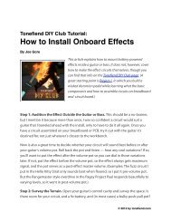
Germanium Booster Project from Tonefiend DIY ... - Seymour Duncan
Germanium Booster Project from Tonefiend DIY ... - Seymour Duncan
Germanium Booster Project from Tonefiend DIY ... - Seymour Duncan

Create successful ePaper yourself
Turn your PDF publications into a flip-book with our unique Google optimized e-Paper software.
tonefiend<br />
<strong>DIY</strong> CLUB<br />
<strong>Project</strong> #4<br />
The Fiendmaster:<br />
A Dallas Rangemaster Spinoff<br />
v03, 02.20.12<br />
©2011 by Joe Gore<br />
1<br />
Monday, February 20, 12
Introducing <strong>Project</strong> #4<br />
tonefiend<br />
<strong>DIY</strong> CLUB<br />
This is a modernized version of the Dallas<br />
Rangemaster — the overdrive circuit that put the<br />
punch in a huge percentage of British rock in the<br />
years surrounding 1970. We’re talking Clapton, Page,<br />
May, Townshend, Bolan, Ronson, Iommi — those<br />
guys.<br />
This is a relatively easy project, and a contender for<br />
a first build. Still, I recommend building <strong>Project</strong> #1<br />
first, or at least reviewing it carefully, because it<br />
introduces many parts and build techniques used<br />
here.<br />
On the other hand, if you’ve built pedals before, dive<br />
right in — the water is scalding!<br />
But please read this document through before<br />
starting, since you’ll have several options along the<br />
way, and you may want to plan and choose parts<br />
accordingly.<br />
©2011 by Joe Gore<br />
2<br />
Monday, February 20, 12
tonefiend<br />
<strong>DIY</strong> CLUB<br />
<strong>Germanium</strong> Transistors:<br />
The Upside<br />
This is our first project to use a germanium transistor.<br />
<strong>Germanium</strong> was used extensively in electronic component production the 1950s and<br />
’60s, but was abandoned in favor of silicon components, which boasted superior<br />
performance, consistency, and value. Today no one cares about rare and finicky<br />
germanium components except certain audio geeks — especially the ones who play<br />
guitars.<br />
It’s difficult to describe the unique qualities of germanium transistors, though the words<br />
“smoother and spongier” seem relevant. They also have a distinctive harmonic profile.<br />
Their overtones shimmer sweetly. Feedback is rich and musical. They are unbelievably<br />
dynamic, yielding excellent and endlessly varied tones throughout the range of the<br />
guitar’s volume knob. Mmm.<br />
Not all vintage fuzz pedals use germanium: Mosrite Fuzzrites, Jordan Bosstones, Foxx<br />
Tone Machines, and Electro-Harmonix Big Muffs are just a few examples of great vintage<br />
fuzzes that used silicon transistors. But the Maestro Fuzz-Tone, the Dallas Rangemaster,<br />
the original Tone Benders, and early Fuzz Faces all used germanium.<br />
©2011 by Joe Gore<br />
3<br />
Monday, February 20, 12
tonefiend<br />
<strong>DIY</strong> CLUB<br />
<strong>Germanium</strong> Transistors:<br />
The Downside<br />
<strong>Germanium</strong> components are usually available only <strong>from</strong> specialized distributors, who<br />
inevitably sell them for many times the cost of their silicon equivalents. (You can find a<br />
list of reliable vendors on the project page at tonefiend.com.)<br />
There’s much variation in quality <strong>from</strong> germanium transistor to germanium transistor.<br />
They’re noisy.<br />
Their tone changes with the air temperature.<br />
The vast majority of surviving germanium transistors are of the PNP variety, which means<br />
they’re engineered for positive-ground circuits, which were common in the ’60s, but nearly<br />
non-existent today. You can’t use a pedal with PNP transistors with a conventional negativeground<br />
power supply unless you jigger with the schematic — which is exactly what we do<br />
here.<br />
You can find NPN, i.e., negative-ground, germanium transistors, but they’re rarer and more<br />
expensive, and you generally have fewer models to choose <strong>from</strong>. If a) you dig the germanium<br />
sound, and b) might want to build more germanium-powered pedals in the future, I suggest<br />
getting into the PNP habit.<br />
©2011 by Joe Gore<br />
4<br />
Monday, February 20, 12
tonefiend<br />
<strong>DIY</strong> CLUB<br />
Working with PNP Transistors<br />
Unlike the NPN transistors we’ve used in previous<br />
projects, PNP-type transistors are designed to<br />
work in positive ground circuits. That creates two<br />
issues:<br />
• You can’t power a positive-ground effect with a<br />
contemporary negative-ground power supply<br />
(though you can use a 9-volt battery).<br />
• Even with a compatible power supply, you swap<br />
PNPs for NPNs (and vice-versa) without altering<br />
the schematic in other ways.<br />
NPN and PNP transistors have separate<br />
schematic symbols.<br />
©2011 by Joe Gore<br />
5<br />
Monday, February 20, 12
tonefiend<br />
<strong>DIY</strong> CLUB<br />
The Original Schematic<br />
Here’s something pretty close to<br />
the original Rangemaster<br />
schematic.<br />
If you want to build a relatively<br />
faithful replica, work <strong>from</strong> this<br />
schematic, omit the DC adapter,<br />
and power it via battery only.<br />
You can try this with any PNP<br />
germanium transistor. But the<br />
relatively common AC-128 will<br />
sound great here.<br />
©2011 by Joe Gore<br />
6<br />
Monday, February 20, 12
tonefiend<br />
<strong>DIY</strong> CLUB<br />
An NPN Version<br />
Here’s a modified version you<br />
can build if you have an NPNtype<br />
germanium transistor.<br />
This works fine with a<br />
conventional negative-ground<br />
power supply.<br />
Note that the orientation of<br />
the 25u electrolytic cap is<br />
reversed relative to the PNP<br />
version.<br />
©2011 by Joe Gore<br />
7<br />
Monday, February 20, 12
Our <strong>Project</strong> Schematic<br />
(basic version)<br />
tonefiend<br />
<strong>DIY</strong> CLUB<br />
Here’s the version we’ll work with in the<br />
following pages.<br />
To deploy a PNP transistor with a negativeground<br />
power supply, we’ve reversed all the<br />
positive and negative connections in the<br />
circuit. The schematic is pretty much “upside<br />
down” relative to the original.<br />
Other changes:<br />
• I’ve swapped the 25u for a more common<br />
22u, which has negligible sonic impact.<br />
• The A50K pot provides a wider variety of<br />
sounds (including all the original ones).<br />
• I prefer a 3.9K value for R3, but by all<br />
means, try the original 4.7K if you like.<br />
©2011 by Joe Gore<br />
8<br />
Monday, February 20, 12
tonefiend<br />
<strong>DIY</strong> CLUB<br />
The Transistor Pinout<br />
Here’s the pinout for the AC128<br />
transistor I used here. It’s the most<br />
common pinout for PNP germanium<br />
transistors.<br />
If it doesn’t work, try swapping the<br />
collector and emitter wires. If that<br />
doesn’t work, find the pinout for your<br />
transistor online — just Google the<br />
part name plus “pinout.” And make sure<br />
you’re not using an NPN-type<br />
transistor.<br />
E<br />
C<br />
B<br />
©2011 by Joe Gore<br />
9<br />
Monday, February 20, 12
Let’s Get Started!<br />
tonefiend<br />
<strong>DIY</strong> CLUB<br />
Connect the power, ground, and audio in/out wires to your<br />
breadboard (as detailed in <strong>Project</strong> #1).<br />
Plug the transistor’s three wires into three different busses, with the<br />
base (here, the middle wire) oriented toward the input.<br />
©2011 by Joe Gore<br />
10<br />
Monday, February 20, 12
tonefiend<br />
<strong>DIY</strong> CLUB<br />
Connect the Transistor’s Base<br />
Connect the transistor’s base to the power bus using a 68K resistor.<br />
Connect the base to ground using a 470K resistor. (In other words,<br />
you’ll have three wires on the same bus.)<br />
©2011 by Joe Gore<br />
11<br />
Monday, February 20, 12
Connect the Collector<br />
tonefiend<br />
<strong>DIY</strong> CLUB<br />
Connect the transistor collector to the power bus using a 3.9K<br />
resistor. Connect the same two points with a 22u electrolytic capacitor.<br />
(Again, you’ll now have three wires on the same bus.) As usual, the<br />
longer leg of the electrolytic cap connects to the power bus.<br />
©2011 by Joe Gore<br />
12<br />
Monday, February 20, 12
tonefiend<br />
<strong>DIY</strong> CLUB<br />
Wire Up Your Pots<br />
3 1<br />
2<br />
Solder three short wires to the lugs of an A50K pot. (You can also use<br />
an A10K, A20K, or A25K, but the A50K affords the widest range of<br />
tones.) Remember that, when viewed <strong>from</strong> the back like this, the pot’s<br />
lugs are numbered as above.<br />
While you’re at it, wire up a B100K pot in the same way. (or use the<br />
alternate wiring shown on page 30). We’ll use this pot later.<br />
©2011 by Joe Gore<br />
13<br />
Monday, February 20, 12
tonefiend<br />
<strong>DIY</strong> CLUB<br />
Connect the Emitter to Ground<br />
Connect lug 3 of the A50K pot to the transistor’s emitter. Connect<br />
lug 1 to ground. Place the wire <strong>from</strong> lug 2 into an empty bus.<br />
©2011 by Joe Gore<br />
14<br />
Monday, February 20, 12
tonefiend<br />
<strong>DIY</strong> CLUB<br />
Connect the Input to the Base<br />
Use a 472 capacitor (also called a .0047uF or a 4.7n) to connect your<br />
input wire to the collector base. The base will now share a bus with<br />
three other wires.<br />
©2011 by Joe Gore<br />
15<br />
Monday, February 20, 12
Connect to the Output<br />
tonefiend<br />
<strong>DIY</strong> CLUB<br />
Connect one leg of a 103 capacitor (also know as a .010uF and a 10n)<br />
to the A50K pot’s lug 2 wire. Connect the other leg of the cap to your<br />
output. (I used an orange jumper wire for this connection.)<br />
©2011 by Joe Gore<br />
16<br />
Monday, February 20, 12
tonefiend<br />
<strong>DIY</strong> CLUB<br />
About that Input Cap . . .<br />
Turn up the A50K pot. You should now hear the pedal in action. The<br />
tone will be a bit trebly, with some of the resonant quality of a fixed<br />
wah pedal. Right now you’re pretty close to the tone of an original<br />
Rangemaster.<br />
If the gain knob works opposite <strong>from</strong> how you want it, just reverse<br />
the wires <strong>from</strong> lugs 1 and 3. (In fact, you can do this anytime you want<br />
to reverse the action of a pot.)<br />
The effect isn’t so much boosting treble as filtering out bass, and<br />
boosting what’s left.<br />
The 472 capacitor (C1) is the filtering element. If you substitute a<br />
smaller-value cap, the tone gets even brighter and tinnier. If you use a<br />
larger value, less bass is removed. The tone not only gets bassier, but<br />
also louder and more distorted, because there’s more overall signal to<br />
drive the transistor.<br />
Let’s try it out.<br />
©2011 by Joe Gore<br />
17<br />
Monday, February 20, 12
tonefiend<br />
<strong>DIY</strong> CLUB<br />
Substitute a Larger Input Cap<br />
Replace the 472 input cap with the larger 104. The effect should<br />
become a much more loud, deep, and distorted. (Don’t be fooled by<br />
the physical cap size — the small blue cap in the pic above is actually<br />
of larger value than the fat gray one in the previous pics.)<br />
©2011 by Joe Gore<br />
18<br />
Monday, February 20, 12
tonefiend<br />
<strong>DIY</strong> CLUB<br />
Congrats! You’re a Musicologist!<br />
You’ve just discovered an<br />
important link in the history of<br />
rock guitar. The emergence of<br />
heavy, power-rock guitar has a<br />
lot to do with Rangemasters<br />
modded with larger input caps<br />
for deeper, more distorted<br />
tones.<br />
Metal starts here.<br />
©2011 by Joe Gore<br />
19<br />
Monday, February 20, 12
tonefiend<br />
<strong>DIY</strong> CLUB<br />
Input Cap Options<br />
You can try different input caps here. The most common values between the 472<br />
and 104 are (in ascending order), 682, 103, 223, 473, and 683. Maybe you’ll find<br />
one that’s perfect for you. (You could also go larger than 104 with a 224 or 474,<br />
but in my experience, that extra bass just makes everything sloppy.)<br />
Or why not make it adjustable? You could switch between two favorite values<br />
with a SPDT switch, or many values using a rotary switch.<br />
Better yet: let’s add another pot to fade between the thin, trebly 472 and the<br />
beefy 104.<br />
©2011 by Joe Gore<br />
20<br />
Monday, February 20, 12
Add a Second Input Cap<br />
tonefiend<br />
<strong>DIY</strong> CLUB<br />
Put the 472 cap back as at was on page 16. Place one leg of the 104<br />
cap into the same bus as the transistor base and the rightmost leg of<br />
the 472. (Yes, you’ll now have five wires in the same bus, and you may<br />
have to reorganize them.) Place the leftmost leg of the 104 in an<br />
empty bus near the input.<br />
©2011 by Joe Gore<br />
21<br />
Monday, February 20, 12
tonefiend<br />
<strong>DIY</strong> CLUB<br />
Add a Tone Pot<br />
Place the wires <strong>from</strong> lugs 2 and 3 of the B100K pot you prepared on<br />
page 13 in the same bus as your input wire. Place the wire <strong>from</strong> lug 1<br />
on the same bus as the leftmost leg of the 104 cap.<br />
Now the distortion tone should thin out as you advance the pot. If<br />
you’d like this control to work the other way around, just swap the<br />
wires <strong>from</strong> lugs 1 and 3. Your final pedal will sound like this.<br />
©2011 by Joe Gore<br />
22<br />
Monday, February 20, 12
Our Final Schematic<br />
tonefiend<br />
<strong>DIY</strong> CLUB<br />
Circuit protection<br />
Noise reduction<br />
LED protection<br />
Prevents switch pops<br />
Before we move on to perfboard, check out this expanded schematic.<br />
It includes the input cap control we just added, plus the usual extras<br />
that don’t effect the tone, but which reduce noise and protect the<br />
circuit.<br />
©2011 by Joe Gore<br />
23<br />
Monday, February 20, 12
tonefiend<br />
<strong>DIY</strong> CLUB<br />
Start Perfboarding!<br />
Prepare a piece of perfboard about this size. Strip several inches <strong>from</strong><br />
a pair of wires and solder them loosely in place for your positive and<br />
negative busses.<br />
©2011 by Joe Gore<br />
24<br />
Monday, February 20, 12
tonefiend<br />
<strong>DIY</strong> CLUB<br />
To Socket or Not to Socket?<br />
Here I’ve used a piece of SIP socket to house the transistor. The advantage: You can<br />
audition different transistors after the circuit is built, and you don’t have to solder the<br />
relatively fragile and valuable germanium transistor. It’s a major pain unsoldering<br />
anything <strong>from</strong> perfboard if you install it incorectly!<br />
On the other hand, it’s easier to solder the long wire legs of the transistor than the<br />
small nubs on the reverse side of the socket material. Your call.<br />
Either way, connect one leg of R1 to the positive bus, one leg of R2 to the negative<br />
bus, and one leg of each to the middle pin of the socket or transistor base.<br />
©2011 by Joe Gore<br />
25<br />
Monday, February 20, 12
tonefiend<br />
<strong>DIY</strong> CLUB<br />
Connect the Dual Input Caps<br />
Connect the rightmost legs of C1 and C4 to the middle socket pin. Place the leftmost<br />
legs in two adjacent columns as shown.<br />
©2011 by Joe Gore<br />
26<br />
Monday, February 20, 12
A Reverse View<br />
tonefiend<br />
<strong>DIY</strong> CLUB<br />
The reverse side of the perfboard will inevitably look like a bloody mess. Just be<br />
careful not to let wires touch where they shouldn’t. It takes some soldering finesse to<br />
connect all those wires to the middle pin of the transistor socket without letting the<br />
solder spill over onto the other two socket pins. (This is the part of the project where<br />
you’ll most regret socketing instead of just soldering in the transistor.)<br />
©2011 by Joe Gore<br />
27<br />
Monday, February 20, 12
Add R3, C2, and C3<br />
tonefiend<br />
<strong>DIY</strong> CLUB<br />
Connect one leg each of R3 and and C3 to the positive bus, and the other legs to the<br />
topmost transistor socket pin.<br />
Insert C3 as shown, but don’t solder it to anything yet.<br />
©2011 by Joe Gore<br />
28<br />
Monday, February 20, 12
Add the Gain Pot<br />
tonefiend<br />
<strong>DIY</strong> CLUB<br />
Connect the wire <strong>from</strong> the A50K pot’s lug 3 to the bottom pin of the transistor<br />
socket. Connect the wire <strong>from</strong> lug 1 to ground. Connect the wire <strong>from</strong> lug 2 to the<br />
leftmost leg of C2`.<br />
©2011 by Joe Gore<br />
29<br />
Monday, February 20, 12
Optional Tone Pot Wiring<br />
tonefiend<br />
<strong>DIY</strong> CLUB<br />
There’s another way you can wire the B100K tone pot: Since both lugs 2 and 3<br />
connect to the same destination, you can make the connection right on the pot,<br />
threading a stripped length of wire through both lugs and soldering it in place. That<br />
way, you only have to place two wires on the crowded perfboard. Again, your call.<br />
©2011 by Joe Gore<br />
30<br />
Monday, February 20, 12
Adding the Tone Pot<br />
tonefiend<br />
<strong>DIY</strong> CLUB<br />
Whether you use two tone pot wires or three, connect lugs 3 and 2 to the leftmost<br />
leg of the 472 cap (C1). Attach an input wire to the same location. Connect the lug 1<br />
wire to the leftmost leg of the 104 cap (C4).<br />
©2011 by Joe Gore<br />
31<br />
Monday, February 20, 12
Add the Output Wire<br />
tonefiend<br />
<strong>DIY</strong> CLUB<br />
Connect an output wire to the rightmost leg of C2.<br />
I’ve also inserted the transistor into the socket. Trim the wires<br />
short enough to keep things neat, but not too short, in case you<br />
ever want to reuse the transistor in another project.<br />
©2011 by Joe Gore<br />
32<br />
Monday, February 20, 12
Add the Extras<br />
tonefiend<br />
<strong>DIY</strong> CLUB<br />
C3<br />
R4<br />
Connect the 1M resistor (R4) between the cluster of wires at the input<br />
and ground. Place the other 22u electrolytic cap (C5) between the<br />
positive and negative busses. Place the 1N4001 diode (which I cleverly<br />
forgot to include in this photo) alongside it, with the banded end<br />
connected to the positive bus.<br />
©2011 by Joe Gore<br />
33<br />
Monday, February 20, 12
Add the LED wiring<br />
tonefiend<br />
<strong>DIY</strong> CLUB<br />
R5<br />
Blue wire will<br />
connect to positive<br />
leg of LED<br />
Connect one end of the 4.7K resistor (R5) to the positive bus. Tuck the<br />
other end of the resistor into a nearby hole, and attach it to a new<br />
wire, which will eventually connect to the positive leg of the power<br />
indicator LED.<br />
©2011 by Joe Gore<br />
34<br />
Monday, February 20, 12
Box It Up!<br />
tonefiend<br />
<strong>DIY</strong> CLUB<br />
Install your circuit in the enclosure.<br />
<strong>Project</strong> #1 includes step-by-step boxing<br />
instructions. The procedure is exactly the<br />
same here.<br />
If the pedal stops working only when you<br />
screw down the back of the enclosure,<br />
something is probably shorting. You can<br />
apply bits of double-sided tape to trouble<br />
spots.<br />
You should now have a ridiculously greatsounding<br />
pedal.<br />
If not, post your problem to<br />
tonefiend.com’s <strong>Project</strong> #4 thread. Chances<br />
are someone can help!<br />
©2011 by Joe Gore<br />
35<br />
Monday, February 20, 12
tonefiend<br />
<strong>DIY</strong> CLUB<br />
What could possibly go wrong?<br />
tonefiend.com<br />
©2011 by Joe Gore<br />
Monday, February 20, 12