Breadboarding a Bad-Ass Distortion Circuit - Seymour Duncan
Breadboarding a Bad-Ass Distortion Circuit - Seymour Duncan
Breadboarding a Bad-Ass Distortion Circuit - Seymour Duncan

You also want an ePaper? Increase the reach of your titles
YUMPU automatically turns print PDFs into web optimized ePapers that Google loves.
tonefiend<br />
DIY CLUB<br />
Project 1, Part 1<br />
<strong>Breadboarding</strong> a <strong>Bad</strong>-<strong>Ass</strong> <strong>Distortion</strong> <strong>Circuit</strong><br />
v02, 10.07.11<br />
©2011 by Joe Gore<br />
1
tonefiend<br />
DIY CLUB<br />
What you’ll do in this project:<br />
A buttload of stuff! You’ll be introduced to the following topics:<br />
• the most common components in guitar electronics<br />
• soldering<br />
• working with a breadboard<br />
• working with a digital multimeter<br />
• decoding a schematic<br />
• assembling a circuit on the breadboard<br />
• modding the circuit to taste<br />
...and you’ll emerge with a wicked-sounding distortion effect, inspired by<br />
the Electra <strong>Distortion</strong>, which has also inspired an huge number of<br />
expensive boutique overdrive pedals. It’s simple, but it sounds killer!<br />
©2011 by Joe Gore<br />
2
What you need for this project:<br />
tonefiend<br />
DIY CLUB<br />
Tools and supplies:<br />
1. Soldering iron (preferably 30 watts or more, but not a gun-type iron)<br />
2. Lead-free solder<br />
3. A damp sponge<br />
4. A small electronics breadboard<br />
5. Hookup wire, preferably 24-gauge, stranded and pre-bonded, in several colors, including black, red, and white<br />
6. An assortment of jumper cables (you could make your own from the above wire, but the prefab kind have metal tips that<br />
don’t fray from repeated use)<br />
7. Wire stripper<br />
8. Wire cutter (most strippers have cutters, but you’ll probably want a separate flush-edged tool for tight, close cuts)<br />
9. Needle-nose pliers<br />
10. A “helping hand” vise<br />
11. An electric guitar, an amp, and two audio cables<br />
12. A digital multimeter with a continuity function. “Auto-ranging” is another plus.<br />
Electronic components:<br />
1. Four resistors. Values: 470R, 10K, 68K, 2.2M.<br />
2. Four capacitors. Values: 473 (sometimes called .047uF or 47n) 683 (AKA .068uF or 68n) and two 104 (.1uF or 100n)<br />
3. Three transistors. Values: 2N5088, 2N5089, and 2N3904.<br />
4. Two potentiometers (“pots”). Values: A100K and C10K. (You can substitute a B10K if you can’t find a C10K.)<br />
5. 9-volt battery.<br />
6. Battery snap (connector).<br />
Not all components will be used in the final project. The extras are for auditioning purposes, so you build according to<br />
your needs and taste.<br />
©2011 by Joe Gore<br />
3
tonefiend<br />
DIY CLUB<br />
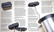
Hi, jack!<br />
inner lug = ground<br />
Meet your basic mono audio jack—and out first soldering task.<br />
On jacks of this type, the outermost lug (the one closest to the nut) carries<br />
the audio signal, while the inner one is your ground.<br />
Stereo jacks, which have a third lug sandwiched between these two, are<br />
most often used in guitar circuits as “kill switch” input jacks for stompboxes<br />
or guitars with battery-powered circuits inside, so that there’s no battery<br />
drain when nothing’s plugged in. But for breadboarding purposes, we’ll go<br />
with two mono jacks.<br />
outer lug = audio signal<br />
©2011 by Joe Gore<br />
4
tonefiend<br />
DIY CLUB<br />
It’s soldering time!<br />
I’ve referenced several “intro to soldering” tutorials at<br />
www.tonefiend.com, and I recommend studying them before<br />
proceeding. These include info about choosing the right iron, and<br />
safety precautions (i.e., don’t touch the hot iron, use lead-free<br />
solder, work in a ventilated area, and wash you hands after working<br />
with this stuff).<br />
Here’s a recap of the basics:<br />
1. Let you iron heat up for a few minutes.<br />
2. Keep a damp sponge handy, and swab the tip of your iron<br />
often to keep it clean.<br />
3. “Tin” the tip by touching a bit of solder to it before starting.<br />
4. When you work, don’t melt solder by touching it to the iron.<br />
Instead, apply the iron to the surfaces you want to bond, and then<br />
touch the solder to the hot surfaces.<br />
5. You may want to use a “helping hands” vise to hold your work.<br />
6. Eye protection recommended!<br />
7. Opt for lead-free solder.<br />
Here I exposed about 1/4-inch of bare wire using the wire stripper. I<br />
threaded it through the lug, and then pinned it in place with the tip<br />
of the iron. Finally, I touched the solder to lug, next to, but not quite<br />
touching, the iron’s tip. When the solder melts, remove the iron, and<br />
then let the solder set (it only takes a couple of seconds).<br />
As a visual aid, you may want to use black wire for the ground lug,<br />
and white for the audio lug.<br />
©2011 by Joe Gore<br />
5
tonefiend<br />
DIY CLUB<br />
Solder both jacks<br />
1. Attach the two wires to both your mono jacks. Snip off any<br />
extra wire.<br />
2. Use about eight inches of wire so you have ample working<br />
room.<br />
Inspect your connections. Good solder joints<br />
look smooth and shiny!<br />
3. Strip about 1/4 inch from the unconnected end of all four<br />
wires.<br />
©2011 by Joe Gore<br />
6
tonefiend<br />
DIY CLUB<br />
Meet the Breadboard<br />
It’s often a good idea to assemble circuits on a breadboard before attempting to solder them to a circuit board. That way, you<br />
can audition sounds before committing to them, and experiment with various options.<br />
Your breadboard may not look exactly like this, but the following comments probably apply.<br />
The outermost lines of holes are connected lengthwise across the diameter of the breadboard. They’re usually color-coded<br />
red and black, with red used for battery power and black used for ground. Any component plugged into one of these “busses”<br />
will be connected to any others plugged in to the same parallel line.<br />
The breadboard pictured here has four busses. Some have more. Only two are needed for our purposes. Also, some<br />
breadboards split the long horizontal busses into two separate regions. If your breadboard has a physical gap midway along<br />
the bus, you may need to insert a jumper cable between the two regions to connect them.<br />
©2011 by Joe Gore<br />
7
tonefiend<br />
DIY CLUB<br />
Meet the Breadboard<br />
The large area between the power and ground busses consists of many smaller, shorter busses. There are oriented<br />
perpendicular to the longer busses.<br />
All the components get laid out in this center area. Some of these will also connect to the longer power and<br />
ground busses.<br />
If you run out of holes on one of these short busses, you can use jumper cables to connect multiple columns.<br />
©2011 by Joe Gore<br />
8
tonefiend<br />
DIY CLUB<br />
Meet the Multimeter<br />
They call it a MULTImeter because it has several functions. First, we’ll check the voltage of our 9V battery by<br />
setting the meter to its DC power function (it’ll probably say “DCV”). Touch the red tip to the battery’s positive<br />
(male) terminal and the black to the negative (female) terminal. If the battery is fresh, it’ll probably read close to<br />
9.5 volts.<br />
©2011 by Joe Gore<br />
9
tonefiend<br />
DIY CLUB<br />
Connect the Battery<br />
Attach your battery snap, and connect the read wire to one of the red busses, and the black to one of the black. (The colors<br />
are just a visual aid—these busses are electronically identical.)<br />
I could have connected the black wire to the black bus right next to the red one, but I used the one at the opposite side of<br />
the breadboard. This is because electronic schematics traditionally show power connections at toward the top of the diagram<br />
and ground connections toward the bottom. Mirroring that arrangement can make it easier to transpose a circuit from a<br />
schematic to a breadboard, as we’ll be doing shortly.<br />
©2011 by Joe Gore<br />
10
tonefiend<br />
DIY CLUB<br />
Let’s Add Audio<br />
Now let’s connect the audio wires. Plug the two ground connections into the ground bus alongside the<br />
negative battery wire. Plug one of the white wires into the upper left-most column, and the other into the<br />
lower left-most column. They are not yet connected.<br />
Plug in both your audio cables. Plug your guitar into the jack connected to the upper-left bus. Plug your amp<br />
into the jack connected to the lower bus.<br />
It’s a good idea to tape stray cables to your work surface. This is going to get messy.<br />
©2011 by Joe Gore<br />
11
Connect the Input and Output<br />
tonefiend<br />
DIY CLUB<br />
To hear the guitar through this circuit, you must<br />
connect the input and output. Connect one end of a<br />
short jumper cable to the input bus, and one to the<br />
output bus. (If you don’t have prefab jumper cables,<br />
you can make you own by stripping the ends from a<br />
short piece of wire. But the prefab ones have metal<br />
pins, so they can be used over and over without<br />
fraying the ends. Trust me, you’ll appreciate this<br />
soon, if you don’t already.)<br />
Turn on your amp. Do you hear your normal sound?<br />
Congrats! You’ve done a bunch of work, and<br />
accomplished nothing! (Yet.)<br />
Don’t hear anything? Verify that your solder<br />
connections are solid. Check that the battery snap is<br />
firmly in place. Triple-check that all wires are in the<br />
correct holes. Make sure your audio cables are<br />
good. (FYI, the battery isn’t doing anything yet. You<br />
could disconnect it at this point and still hear your<br />
guitar.)<br />
And use your new troubleshooting tool: the<br />
multimeter!<br />
©2011 by Joe Gore<br />
12
tonefiend<br />
DIY CLUB<br />
Troubleshooting with the Multimeter<br />
Set your multimeter to its “continuity” function. This<br />
is simply a beeper that sound whenever you touch<br />
the test leads to two properly connected point in a<br />
circuit.<br />
If you hear your guitar now as you should, try<br />
touching the leads to the “hot” lugs of the two jacks<br />
(the ones with white wire).<br />
If you hear guitar and a beep, you’re awesome.<br />
If you hear guitar but no beep, you haven’t set your<br />
meter properly.<br />
If you hear a beep but no guitar, you have a bad<br />
cable, your amp isn’t on, or your guitar’s volume is<br />
turned down.<br />
If you hear no guitar and no beep, remove the wires<br />
and components from the breadboard and use the<br />
continuity function to test the individual pieces. For<br />
example, touch one lead to a jack lug, and the other<br />
to the end of the wire connected to it.<br />
Get used to this view.<br />
You’ll see it often.<br />
©2011 by Joe Gore<br />
13
tonefiend<br />
DIY CLUB<br />
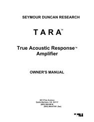
Your Pal, the Schematic<br />
A schematic is a graphic representation of a circuit.<br />
These can be incredibly complicated, but this one’s<br />
easy. You only need to learn a half-dozen symbols.<br />
(To learn more, just Google “schematic symbols.”)<br />
Typically, audio input is shown on the left, and output<br />
on the right. Power appears at the top, and ground<br />
at the bottom.<br />
Squiggly lines = resistors<br />
The circle thingie is a transistor<br />
The dashed triangle means<br />
it connects ground<br />
The numbers next to each component are the<br />
values (for example, “104,” or “68K”). The numbers<br />
in parentheses are just an ID for each component,<br />
which allows us to say things like, “If you hear too<br />
much bass, try replacing C1 with a 683 or 473.”<br />
Parallel lines = capacitors<br />
©2011 by Joe Gore<br />
14
tonefiend<br />
DIY CLUB<br />
What Does What?<br />
1. Your guitar signal enters here. C1 acts as<br />
a filter. A smaller capacitor removes more<br />
lows.<br />
2. The transistor amplifies your guitar signal<br />
—so much so that it distorts. Different<br />
transistors provide different amounts of<br />
gain. The guitar signal enters at the base (the<br />
middle pin, in our case), and emerges from<br />
the collector.<br />
3. The battery powers the transistor via its<br />
collector. R2 regulates the amount of<br />
current reaching the transistor.<br />
4. R3 regulates the amount of current<br />
flowing from the transistor’s emitter to<br />
ground. Lower values equal more gain.<br />
5. R1 adds some current from the battery to<br />
the pre-transistor input signal.<br />
6. C2 converts the DC signal to AC before it<br />
hits your guitar amp (or other stompboxes).<br />
1<br />
5<br />
3<br />
2<br />
4<br />
6<br />
Note: To get you up and running with minimum<br />
theorizing, these explanations are very simplified.<br />
Check out the recommended reading at the end of<br />
this article for more info.<br />
©2011 by Joe Gore<br />
15
tonefiend<br />
DIY CLUB<br />
Here Comes Trouble: The Transistor!<br />
Here’s where the godawful noise magic happens.<br />
In these first few projects, the transistor will work<br />
as an amplifier. In this project, it will amplify so much<br />
that it will distort. A lot.<br />
We’re going to audition three transistors in this<br />
circuit: a 2N3904, a 2N5088, and a 2N5089. All three<br />
are of a type known as the silicon BJT (bi-junction<br />
transistor). This is just one of many types.<br />
While our initial projects all use a single transistor,<br />
some circuits use many of them. In fact, the number<br />
of transistors is one of the defining properties of<br />
many boost/overdrive/distortion/fuzz circuits. (Fuzz<br />
Faces use two, Tone Benders usually use three, and<br />
Big Muffs have four).<br />
More isn’t better—just different. Many great circuits<br />
use just one transistor. Examples include the mighty<br />
Dallas-ArbiterRangemaster, the crispy-clean Z. Vex<br />
Super Hard On, and the popular Electra distortion<br />
circuit, from which this project is derived.<br />
©2011 by Joe Gore<br />
16
tonefiend<br />
DIY CLUB<br />
The ABCs of CBE<br />
Transistors of this type have three terminals: the<br />
collector, base, and emitter, often abbreviated as C,<br />
B, and E.<br />
C<br />
The collector “collects” juice from the red power<br />
bus. Your guitar signal goes to the base. And the<br />
emitter connects to the ground bus. But in most<br />
cases, there are one or more components between<br />
the C, B, and E pins and those destinations.<br />
Confused? Sadly, it gets worse.<br />
The location of the C, B, and E pins can vary from<br />
one transistor type to another, even ones that look<br />
identical! This pattern is called the “pinout.” Varying<br />
pinouts are among the biggest pains in DIY<br />
electronics.<br />
Thankfully, the three transistors used in this project<br />
share the same pinout. With the plastic part toward<br />
you, and its rounded side facing left, the pinout it C,<br />
B, E, from top to bottom.<br />
E<br />
B<br />
The above pinout applies to the<br />
three BJTs used in this project<br />
—but sadly, not all transistors.<br />
Hint: It’s easy to check a pinout online. For example,<br />
just Google “2N5088 pinout,” and you’ll find your<br />
way to a manufacturer’s spec sheet with all the<br />
necessary info.<br />
©2011 by Joe Gore<br />
17
tonefiend<br />
DIY CLUB<br />
Place the Transistor<br />
Even though the transistor’s terminals are<br />
shown top-to-bottom in the schematic, we must<br />
place it sideways—otherwise, the three<br />
connection would all be linked on the same bus.<br />
The exact position on the breadboard doesn’t<br />
matter. Anything like this will work.<br />
As positioned here, with the curved side facing<br />
up, the collector (C) is to the right, and the<br />
emitter (E) is to the left.<br />
Use the 2N3904 transistor to start. Later we’ll<br />
audition the others.<br />
©2011 by Joe Gore<br />
18
tonefiend<br />
DIY CLUB<br />
Working with Resistors<br />
Resistors are not polarized, which means it<br />
doesn’t matter which way you insert them.<br />
There are three ways to measure the value of<br />
resistors:<br />
1. Read the bag it came in. This is my favorite<br />
technique.<br />
2. Memorize the resistor color codes. This is my<br />
least favorite technique.<br />
3. Use the multimeter’s ohmmeter function. This<br />
is usually indicated by an omega symbol (Ω). Just<br />
touch the test leads to the two terminals. (If your<br />
multimeter doesn’t have auto-ranging, you may<br />
have to manually adjust the range to get a<br />
reading.)<br />
To test resistors, you must remove them from<br />
the circuit, as shown here. The values can vary by<br />
as much as 10%, so don’t sweat it if, say, your 10K<br />
resistor reads as 9.77K.<br />
©2011 by Joe Gore<br />
19
tonefiend<br />
DIY CLUB<br />
Connect the Transistor to the Battery<br />
Use the 68K resistor to connect the transistor’s collector to the 9V bus.<br />
Use the 470R resistor to connect the transistor’s emitter to ground.<br />
©2011 by Joe Gore<br />
20
tonefiend<br />
DIY CLUB<br />
Place a Resistor Between<br />
the Transistor’s Collector and Base<br />
Place the 2.2M resistor between the transistor’s collector and base.<br />
(You will now have two resistors connected to the collector.)<br />
©2011 by Joe Gore<br />
21
Working with Capacitors<br />
tonefiend<br />
DIY CLUB<br />
In some cases, the orientation of the capacitor<br />
(or “cap”) matters, but not with the caps we’re<br />
using here.<br />
The value of the cap is important, but the cap<br />
type usually isn’t. Mylar, ceramic, and box-type<br />
caps all work equally well here.<br />
Cap values are printed on the component. But<br />
sadly, there are three different ways of denoting<br />
cap values.<br />
Here are the three ways of referring to the cap<br />
values used in this project:<br />
104 = .1uF = 100n<br />
683 = .068uF = 68n<br />
473 = .047uF = 47n<br />
Google “capacitor values” for more info.<br />
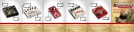
Three 104 capacitors types: mylar film, ceramic,<br />
and box (also mylar, but in a slicker package).<br />
They’ll sound identical in this circuit.<br />
©2011 by Joe Gore<br />
22
tonefiend<br />
DIY CLUB<br />
Connect the Input and Output Caps<br />
Use one of the 104 caps to link the white input wire and the transistor base (middle pin).<br />
You could probably do this without using a jumper cable, but it would get messy. Instead,<br />
just install it as shown and use a jumper wire to complete the connection.<br />
Use the other 104 cap to connect the transistor collector (rightmost pin) to output.<br />
(You will now have four items plugged into the same vertical bus.) Use another jumper<br />
cable to connect the other end of the cap to the white output wire, as shown.<br />
©2011 by Joe Gore<br />
23
Hope you had your amp turned down!<br />
You should now hear insanely loud guitar<br />
distortion.<br />
tonefiend<br />
DIY CLUB<br />
This is the circuit at maximum loudness.<br />
We’ll be shaping and controlling it in Part 2<br />
of this project.<br />
If you get anything other than heavy-duty<br />
distortion, quadruple-check all connections<br />
(especially those confusing transistor pins).<br />
Compare your work to the v01 schematic,<br />
and use the multimeter’s continuity function<br />
to verify adjacent connections.<br />
BTW, it’s extremely rare for any of these<br />
components to fail. If the circuit doesn’t<br />
work as expected, you can pretty much bet<br />
that the cause is human error. (One<br />
exception: Cheap jumper cables can be<br />
funky. Try swapping these out if necessary.)<br />
Coming next in Part 2: Shaping and Modding the <strong>Circuit</strong>!<br />
©2011 by Joe Gore
tonefiend<br />
DIY CLUB<br />
Appendix: Recommended Reading<br />
Here are three fine “electronics for beginners”books:<br />
Getting Started in Electronics by Forrest M. Mimms III<br />
Electronics for Dummies by Cathleen Shamieh and Gordon McComb<br />
Make:Electronics Book by Charles Platt<br />
But to be honest,most of you self-education is likely to take place online. I particularly<br />
recommend three stompbox-building sites as great places for beginners to learn.<br />
diystombboxes is probably the largest online builders community. Their forum is a great<br />
place to ask questions,and the FAQ section of the diystompboxes wiki is so helpful<br />
you may want to print out a hard copy,if not tattoo it on your forearms.<br />
My favorite DIY writer is Dano from Beavis Audio Research. Sadly,his site is dormant,but<br />
his many fine articles are still posted there. He’s funny and pragmatic,with a knack for zeroing in<br />
on the crucial info. I recommend everything in his Tech Section,especially<br />
this,this,this,this,this,this,this,this,and this. And be sure to archive copies,in case this<br />
resource ever vanishes.<br />
Gaussmarkov DIY Effects is more sober than the fun-loving Beavis site. But in addition to<br />
hosting many fabulous stompbox projects,Gaussmarkov boasts a fine tech section with<br />
articles dedicated to all the key components.<br />
©2011 by Joe Gore<br />
25