Defects in inorganic photorefractive materials and their investigations
Defects in inorganic photorefractive materials and their investigations
Defects in inorganic photorefractive materials and their investigations

You also want an ePaper? Increase the reach of your titles
YUMPU automatically turns print PDFs into web optimized ePapers that Google loves.
<strong>Defects</strong> <strong>in</strong> <strong>in</strong>organic <strong>photorefractive</strong> <strong>materials</strong><br />
<strong>and</strong> <strong>their</strong> <strong>in</strong>vestigations<br />
B. Briat 1 ,V.G.Grachev 2,3 ,G.I.Malovichko 3 ,O.F.Schirmer 2 ,<strong>and</strong><br />
M. Wöhlecke 2<br />
1 Laboratoire d’Optique Physique, ESPCI, 75231 Paris Cedex 05, France<br />
Briat.Bernard@wanadoo.fr<br />
2 Fachbereich Physik, Universität Osnabrück, D-49069 Osnabrück, Germany<br />
Schirmer@uos.de<br />
3 Department of Physics, Montana State University, Bozeman, MT 59717, USA<br />
Malovichko@physics.montana.edu<br />
1 Introduction<br />
The role of defects <strong>in</strong> the <strong>photorefractive</strong> effect is known <strong>in</strong> pr<strong>in</strong>ciple: <strong>their</strong><br />
photoionization <strong>in</strong> the brighter regions of a <strong>photorefractive</strong> crystal, illum<strong>in</strong>ated<br />
by an <strong>in</strong>homogeneous light pattern, causes quasifree charge carriers. These are<br />
separated from <strong>their</strong> home sites by diffusion, by the bulk photovoltaic effect<br />
or by drift <strong>in</strong> an external electric field. Eventually they are trapped at empty<br />
levels of defects <strong>in</strong> the darker regions, <strong>and</strong> a space charge field is created.<br />
Crystals with a l<strong>in</strong>ear electrooptic effect transform this <strong>in</strong>to a refractive <strong>in</strong>dex<br />
pattern. Theoretically also the rates of the ionization process, the transport<br />
<strong>and</strong> the trapp<strong>in</strong>g can be formulated quantitatively. This Chapter gives <strong>in</strong>formation<br />
how this general picture may be filled by real defects <strong>in</strong> exist<strong>in</strong>g<br />
<strong>photorefractive</strong> crystals.<br />
A few classes of <strong>in</strong>organic <strong>materials</strong> are available - lithium niobate <strong>and</strong><br />
related compounds, the ferroelectric oxide perovskites, the sillenites, some<br />
acentric semiconductors, <strong>and</strong> various other compounds - which show properties<br />
favorable for <strong>photorefractive</strong> operation, as far as the host lattice is concerned.<br />
There is a large number of possibilities to optimize <strong>their</strong> performance<br />
by <strong>in</strong>troduc<strong>in</strong>g suitable defects. In this way the follow<strong>in</strong>g features of a <strong>photorefractive</strong><br />
material can be <strong>in</strong>fluenced: magnitude <strong>and</strong> spectral dependence<br />
of the <strong>photorefractive</strong> sensitivity, speed of the charge transport, lifetime of<br />
carrier trapp<strong>in</strong>g etc.<br />
Optical absorption of a photon by a defect is the primary step trigger<strong>in</strong>g<br />
the <strong>photorefractive</strong> effect. Most often, however, the absorption b<strong>and</strong>s by themselves<br />
do not <strong>in</strong>dicate which lattice perturbation causes them; they have to be<br />
assigned first to <strong>their</strong> orig<strong>in</strong> by a method sensitive to the microscopic structure<br />
of defects. Studies of electron paramagnetic resonance (EPR), together
2 B. Briat et al.<br />
with its extensions, are unsurpassed <strong>in</strong> furnish<strong>in</strong>g such <strong>in</strong>formation, <strong>and</strong> methods<br />
have been developed to transfer this knowledge to the optical absorption<br />
phenomena. They will be outl<strong>in</strong>ed below. Detailed knowledge on defects <strong>in</strong><br />
<strong>photorefractive</strong> <strong>materials</strong> <strong>and</strong> the reliable <strong>in</strong>terpretation of <strong>their</strong> absorption<br />
b<strong>and</strong>s thus rests almost exclusively on EPR <strong>and</strong> EPR-related <strong>in</strong>vestigations.<br />
The Mössbauer effect may be cited as an exception; unfortunately it is essentially<br />
restricted to iron conta<strong>in</strong><strong>in</strong>g defects. Therefore the Chapter ma<strong>in</strong>ly<br />
rests on <strong>in</strong>vestigations by EPR <strong>and</strong> related methods.<br />
In ideal situations, studies of defects furnish knowledge of <strong>their</strong> structure,<br />
<strong>in</strong>clud<strong>in</strong>g the chemical identity, geometry <strong>and</strong> charge state, of the <strong>in</strong>corporation<br />
site <strong>in</strong> the lattice, the nature of the electronic ground <strong>and</strong> excited states<br />
<strong>and</strong> <strong>their</strong> energies, the optical <strong>and</strong> thermal excitation mechanisms, the light<strong>in</strong>duced<br />
transfer of charges to the valence <strong>and</strong> conduction b<strong>and</strong>s <strong>and</strong>, on this<br />
basis, the prediction of the <strong>photorefractive</strong> performance of a material. In some<br />
cases these aims could be achieved rather closely, generally, however, many<br />
questions rema<strong>in</strong> unanswered <strong>and</strong> offer opportunities for further research.<br />
Several chapters <strong>in</strong> the two volumes on <strong>photorefractive</strong> <strong>materials</strong> edited<br />
by Günter <strong>and</strong> Huignard <strong>in</strong> 1988 [1] conta<strong>in</strong> <strong>in</strong>formation on defects <strong>in</strong> such<br />
compounds. S<strong>in</strong>ce then new methods for defect <strong>in</strong>vestigation have been developed<br />
<strong>and</strong> the range of results obta<strong>in</strong>ed <strong>in</strong> the field has vastly exp<strong>and</strong>ed. This<br />
Chapter will give a survey of the present status of the studies. It starts with<br />
a brief general overview on the properties of defects <strong>and</strong> <strong>their</strong> classification;<br />
then an <strong>in</strong>troduction to the experimental methods employed will follow. The<br />
later sections will deal with the defect related results obta<strong>in</strong>ed for the various<br />
classes of <strong>photorefractive</strong> <strong>in</strong>organic <strong>materials</strong>. Also a short section cover<strong>in</strong>g the<br />
properties of hydrogen <strong>in</strong> oxide <strong>materials</strong> is <strong>in</strong>cluded. The brevity necessary<br />
for cover<strong>in</strong>g a large field of research <strong>in</strong> a short chapter will be compensated<br />
by giv<strong>in</strong>g an extended list of references. For a recent review on defects <strong>in</strong> <strong>in</strong>organic<br />
<strong>photorefractive</strong> <strong>materials</strong> with an emphasis on applications, an article<br />
by Buse [2] can be consulted.<br />
2 Classification <strong>and</strong> general properties of defects<br />
A defect is anyth<strong>in</strong>g which perturbs the translational symmetry of a crystal.<br />
In this Chapter the term defect will be used <strong>in</strong> a narrower sense: only po<strong>in</strong>t like<br />
perturbations will be treated, i.e. cases where an ion of the lattice is miss<strong>in</strong>g<br />
or lattice sites are replaced by nonregular ions. Also, small clusters of such<br />
po<strong>in</strong>t defects may be <strong>in</strong>cluded. If only ions are <strong>in</strong>volved which belong to the<br />
ideal crystal, the defects are <strong>in</strong>tr<strong>in</strong>sic, otherwise they are extr<strong>in</strong>sic. Examples<br />
for <strong>in</strong>tr<strong>in</strong>sic defects are vacancies or antisite defects. A Bi ion replac<strong>in</strong>g Si<br />
<strong>in</strong> the sillenite Bi 12 SiO 20 , labelled Bi Si , is an example of the latter. In this<br />
article we mostly use this type of labell<strong>in</strong>g; the chemical symbol for the ion<br />
present is appended by a subscript, mark<strong>in</strong>g the site of replacement. The<br />
letter ’V’ is used <strong>in</strong> this context as a symbol for vacancy; e.g. ’V O ’ st<strong>and</strong>s for
<strong>Defects</strong> <strong>in</strong> <strong>in</strong>organic <strong>photorefractive</strong> <strong>materials</strong> <strong>and</strong> <strong>their</strong> <strong>in</strong>vestigations 3<br />
oxygen vacancy. If the charge of the defect is to be <strong>in</strong>dicated, a correspond<strong>in</strong>g<br />
superscript is added. Sometimes the charges are referred to that of the replaced<br />
ion, then Bi x Si is used for an antisite defect, if the replac<strong>in</strong>g <strong>and</strong> the replaced ion<br />
have the same charges. If the replac<strong>in</strong>g one is negative (positive), the notation<br />
is Bi ′ Si (Bi• Si ). Also the label Bi4+<br />
Si<br />
, <strong>in</strong>dicat<strong>in</strong>g the electronic configuration of the<br />
defect ion, may be used for the neutral case <strong>and</strong> Bi 3+<br />
Si<br />
(Bi 5+<br />
Si<br />
) for the negative<br />
(positive) one. For an overview on defect notations see Ref. [3].<br />
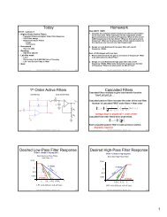
Fig. 1. Def<strong>in</strong>ition of defect levels,<br />
illustrated with the three basic<br />
models for charge transfer between<br />
defects <strong>in</strong> <strong>photorefractive</strong><br />
crystals [4]. The special cases are<br />
shown, where electrons are transferred<br />
from the valence b<strong>and</strong> to<br />
the defect levels. Electron transfer<br />
from defect levels to the conduction<br />
b<strong>and</strong> would lead to complementary<br />
schemes. Double arrows<br />
<strong>in</strong>dicate light-<strong>in</strong>duced transfer,<br />
s<strong>in</strong>gle arrows recomb<strong>in</strong>ation<br />
of a defect electron with a valence<br />
b<strong>and</strong> hole. a): one - center<br />
model: under illum<strong>in</strong>ation the total<br />
concentrations X 0 <strong>and</strong> X − are<br />
not changed. The model therefore<br />
does not lead to photochromicity.<br />
b, c): Here the shallow levels are<br />
metastably populated after optical<br />
excitation. The concentrations<br />
of the defect charge states change,<br />
lead<strong>in</strong>g to photochromicity.<br />
As a consequence of the broken translational symmetry, defects can <strong>in</strong>troduce<br />
levels <strong>in</strong> the gap between valence <strong>and</strong> conduction b<strong>and</strong>, which represent<br />
the eigenenergies of an ideal crystal. Depend<strong>in</strong>g on the position of the Fermilevel<br />
<strong>in</strong> the crystal, such defect levels may be occupied by electrons or be<br />
empty. For oxide <strong>materials</strong>, reduction <strong>and</strong> oxidation are convenient means to<br />
shift the Fermi-level. The <strong>photorefractive</strong> effect is based on the fact that the<br />
level population can also be changed by illum<strong>in</strong>ation, especially <strong>in</strong> oxide <strong>materials</strong><br />
often <strong>in</strong> a metastable manner. A level <strong>in</strong>troduced by a defect X, where<br />
the charge state ’0’ is assumed to coexist with the charge state ’-’ , is labelled<br />
X 0/− (Fig. 1), <strong>in</strong> analogy to the notation for redox-pairs <strong>in</strong> electrochemistry,<br />
see e.g. [5]. This means: if the level lies at an energy E X above the valence
4 B. Briat et al.<br />
b<strong>and</strong> edge, E X must be expended <strong>in</strong> order to excite a valence b<strong>and</strong> electron<br />
to the defect X 0 ,transform<strong>in</strong>git<strong>in</strong>toX − .<br />
Especially <strong>in</strong> oxide crystals, the charge carriers tend to couple strongly to<br />
the lattice. S<strong>in</strong>ce optical excitations take place under Franck-Condon conditions,<br />
i. e. with the ’lattice kept fixed’ [5, 6], <strong>in</strong> the case of strong coupl<strong>in</strong>g,<br />
thermal levels must be dist<strong>in</strong>guished from optical ones (for an example see<br />
Fig. 2): The f<strong>in</strong>al state reached by the optical transition ends <strong>in</strong> the optical<br />
level, ly<strong>in</strong>g higher than the vibrational ground state, the thermal level; for<br />
an example, see section 5. In oxide crystals energy differences between both<br />
types of levels up to about 2.3 eV [7] have been found!<br />
optical<br />
1.6 eV<br />
4+<br />
Rh<br />
3+<br />
4+<br />
3+ thermal<br />
0.95 eV<br />
Fig. 2. Discrim<strong>in</strong>ation between optical<br />
<strong>and</strong> thermal levels, exemplified for<br />
Rh 4+/3+ <strong>in</strong> BaTiO 3 (see Section 5).<br />
The elastic lattice energies, correspond<strong>in</strong>g<br />
to the electronic groundstate<br />
(upper edge of valence b<strong>and</strong>)<br />
<strong>and</strong> to the electron excited to the defect,<br />
are shown as depend<strong>in</strong>g on a<br />
configuration coord<strong>in</strong>ate Q [6]. Double<br />
arrow: transition to optical level,<br />
vertical <strong>in</strong> Q-space. Wavy arrow: vibrational<br />
transition to thermal level.<br />
Such charge transfer transitions (e.g. from a valence b<strong>and</strong> oxygen ion to<br />
a defect) or <strong>in</strong>tervalence transitions (from a defect to a conduction b<strong>and</strong> ion)<br />
usually are rather strong, because the electron moves through a considerable<br />
distance, correspond<strong>in</strong>g to a large transition moment [5]. The range of the<br />
transfer is limited by the covalent mixture between the states of the <strong>in</strong>itial<br />
<strong>and</strong> f<strong>in</strong>al ions; this is strongest between those nearest to each other. On the<br />
other h<strong>and</strong>, <strong>in</strong>ternal transitions of crystal field type occur e.g. among the d-<br />
states of one transition metal ion. For ions at crystal sites hav<strong>in</strong>g <strong>in</strong>version<br />
symmetry, such excitations thus are parity forbidden [5]. They become easily<br />
observable <strong>in</strong> situations without <strong>in</strong>version symmetry, e. g. at the tetrahedral<br />
sites of sillenite crystals. Such transitions can also be stronger, if the excited<br />
state is resonant with the conduction b<strong>and</strong>. As a general rule it can still be<br />
stated that the <strong>photorefractive</strong> effect is triggered most decisively by charge<br />
transfer or <strong>in</strong>tervalence transitions, both because they are strong <strong>and</strong> because<br />
they lead to defect photoionization.<br />
A further important consequence of lattice coupl<strong>in</strong>g is the formation of<br />
polarons. This term is related to the equivalence of correspond<strong>in</strong>g lattice sites<br />
<strong>in</strong> crystals (Fig. 3). The tunnell<strong>in</strong>g of a charge carrier between these sites competes<br />
with the lattice distortion, tend<strong>in</strong>g to break the equivalence by spon-
<strong>Defects</strong> <strong>in</strong> <strong>in</strong>organic <strong>photorefractive</strong> <strong>materials</strong> <strong>and</strong> <strong>their</strong> <strong>in</strong>vestigations 5<br />
taneously localiz<strong>in</strong>g the carrier (Fig. 3). For more details see Ref. [8]. The<br />
<strong>in</strong>terplay between tunnell<strong>in</strong>g <strong>and</strong> the lattice distortion [8] decides whether a<br />
polaron is of large size (e.g. for electrons <strong>in</strong> the conduction b<strong>and</strong> of the sillenites<br />
[9]), or of small or <strong>in</strong>termediate size (e.g. conduction electrons <strong>in</strong> BaTiO 3<br />
[10]). The features of such polarons determ<strong>in</strong>e the carrier mobility, <strong>in</strong>fluenc<strong>in</strong>g<br />
the speed of the <strong>photorefractive</strong> effect. Under favorable conditions, two<br />
polarons can comb<strong>in</strong>e <strong>in</strong>to bipolarons [8]. This occurs when the Coulomb repulsion<br />
between the carriers is overcompensated by the surplus stabilization<br />
energy caused by <strong>their</strong> jo<strong>in</strong>t lattice distortion.<br />
Fig. 3. Left: Sketch of a crystal lattice with translational symmetry with one added<br />
electron. If the tunnell<strong>in</strong>g from site to site is not too strong, an electron is shown to be<br />
self-localized at one lattice site by repell<strong>in</strong>g its neighbors, spontaneously break<strong>in</strong>g<br />
the equivalence of sites. Right: The total energy of a polaron is the sum of the<br />
lattice elastic energy, 1 2 KQ2 , <strong>and</strong> the lower<strong>in</strong>g of the electronic energy by repell<strong>in</strong>g<br />
the neighbors, −FQ. For two electrons <strong>in</strong> a bipolaron, the lower<strong>in</strong>g of the electronic<br />
energy is doubled, −2FQ, the total energy lower<strong>in</strong>g quadrupled, 4 E P . If the energy<br />
excess for two paired electrons, 4 E P ,ascomparedtotwoseparatedelectrons,2E P ,<br />
overcompensates the Coulomb repulsion, a bipolaron is stable.<br />
Also, polarons usually lead to strong optical absorptions. For small polarons,<br />
where the carrier is self-trapped at essentially one lattice ion, the<br />
correspond<strong>in</strong>g transitions occur from the <strong>in</strong>itial trapp<strong>in</strong>g site of a carrier to<br />
a f<strong>in</strong>al equivalent one. This represents a special case of a charge transfer or<br />
<strong>in</strong>tervalence transition. Therefore, also, large transition moments are <strong>in</strong>volved,<br />
lead<strong>in</strong>g to high absorption <strong>in</strong>tensities. The absorption energies are f<strong>in</strong>ite, <strong>in</strong><br />
spite of the equivalence of <strong>in</strong>itial <strong>and</strong> f<strong>in</strong>al sites, because the transitions occur<br />
under Franck-Condon conditions.<br />
Charge carriers bound to a defect can also exhibit polaron effects [7, 11].<br />
Consider, e.g. a Bi 3+ ion replac<strong>in</strong>g a Si 4+ ion <strong>in</strong> the sillenite Bi 12 SiO 20 . This<br />
is the negatively charged antisite defect Bi ′ Si , see Fig. 12 <strong>in</strong> Section 6. Photoionisation<br />
takes an electron not from Bi 3+ but from the four tetrahedrally<br />
arranged equivalent O 2− ions surround<strong>in</strong>g Bi. The created hole is self-trapped<br />
at one of these oxygen ions, form<strong>in</strong>g a bound small polaron by spontaneously
6 B. Briat et al.<br />
break<strong>in</strong>g <strong>their</strong> equivalence. Also such bound polarons lead to strong optical<br />
absorptions [7, 11], due to the long transition dipole between the <strong>in</strong>itial <strong>and</strong><br />
a neighbor<strong>in</strong>g oxygen ion <strong>in</strong> the tetrahedron. For more details, see Section 6.<br />
Some of the <strong>photorefractive</strong> crystals, such as congruently melt<strong>in</strong>g LiNbO 3<br />
(LN), Sr 1−x Ba x Nb 2 O 6 (SBN)orBa 1−x Ca x TiO 3 (BCT), are strongly disordered.<br />
This leads to considerable spatial fluctuations of the defect levels,<br />
caus<strong>in</strong>g wide l<strong>in</strong>es <strong>in</strong> all spectroscopic studies [12]. Furthermore, the mobility<br />
of quasifree charge carriers tends to be reduced <strong>in</strong> such <strong>materials</strong>.<br />
3 Methods of defect <strong>in</strong>vestigation<br />
We start by giv<strong>in</strong>g a qualitative overview of the electron paramagnetic resonance<br />
(EPR) method. The electronic ground state of a paramagnetic defect<br />
is characterized by its spatial distribution <strong>and</strong> by its sp<strong>in</strong> number. With<strong>in</strong><br />
the spatial range of <strong>their</strong> wavefunction, the unpaired electrons collect all <strong>in</strong>teractions<br />
by which they can couple with <strong>their</strong> surround<strong>in</strong>gs, among these:<br />
sp<strong>in</strong>-sp<strong>in</strong>- <strong>and</strong> sp<strong>in</strong>-orbit-coupl<strong>in</strong>g, also <strong>in</strong> comb<strong>in</strong>ation with crystal fields, <strong>and</strong><br />
hyperf<strong>in</strong>e <strong>in</strong>teraction of the electrons with the ’visited’ nuclei, represent<strong>in</strong>g local<br />
probes <strong>in</strong> the crystal. If a static external magnetic field is applied, Zeeman<br />
<strong>in</strong>teraction is also active. EPR methods probe the energy splitt<strong>in</strong>gs between<br />
the lowest states caused by these coupl<strong>in</strong>gs. The external magnetic field provides<br />
a reference direction <strong>and</strong> thus allows the symmetry of the <strong>in</strong>teractions<br />
to be identified. They are of tensorial character if the defect as a whole or<br />
the positions of the <strong>in</strong>teract<strong>in</strong>g nuclei are non-cubic. This analysis leads to<br />
the most essential <strong>in</strong>formation supplied by the method: the symmetry of the<br />
coupl<strong>in</strong>g tensors <strong>and</strong> the orientation of <strong>their</strong> pr<strong>in</strong>cipal axes with respect to the<br />
crystal lattice, strongly narrow<strong>in</strong>g down possible defect models. For a recent<br />
overview on the application of EPR <strong>and</strong> related techniques, especially optical<br />
ones, to the elucidation of defect properties see, e.g., Ref. [13].<br />
It is an advantage of the EPR method that it allows to determ<strong>in</strong>e the concentration<br />
of paramagnetic defects [14], open<strong>in</strong>g the way to the quantitative<br />
analysis of the performance of a <strong>photorefractive</strong> material on the basis of EPR<br />
studies alone. For further details see Section 5. EPR can ’count’ defect densities<br />
down to a few ppm. Only neutron activation analysis, see for example [15]<br />
is more sensitive. But there it is not possible to detect <strong>in</strong>tr<strong>in</strong>sic defects or to<br />
differentiate between the various charge states which the same defect element<br />
can assume, such as e.g. Fe 3+ <strong>and</strong> Fe 5+ , a task which can be solved by EPR.<br />
All <strong>in</strong>teractions probed by the electron(s) are usually summarized by a<br />
sp<strong>in</strong>-Hamiltonian, for example:<br />
H = µ B BgS + SDS + ∑ SA i I i + ..... (1)<br />
where only three representative terms are given for illustration. The first one<br />
describes the Zeeman <strong>in</strong>teraction, the second a crystal field <strong>in</strong>teraction <strong>and</strong>
<strong>Defects</strong> <strong>in</strong> <strong>in</strong>organic <strong>photorefractive</strong> <strong>materials</strong> <strong>and</strong> <strong>their</strong> <strong>in</strong>vestigations 7<br />
the last one the hyperf<strong>in</strong>e <strong>in</strong>teraction. Here µ B is the Bohr magneton, B the<br />
external magnetic field vector, g the tensor of the Zeeman <strong>in</strong>teraction, S the<br />
sp<strong>in</strong> operator (2S + 1 is the multiplicity of the lowest level considered), D a<br />
crystal field tensor, I i the sp<strong>in</strong> operator of nucleus i <strong>and</strong> A i the tensor of the<br />
hyperf<strong>in</strong>e <strong>in</strong>teraction. The Hamiltonian usually operates only on the (2S +1)<br />
lowest states <strong>and</strong> is thus called a sp<strong>in</strong>-Hamiltonian.<br />
Fig. 4. Basic schemes for paramagnetic resonance <strong>and</strong> related methods, demonstrated<br />
for one electron sp<strong>in</strong>, S = 1 . 2<br />
EPR: One transition occurs between the m s = ± 1 states, Zeeman - split by a static<br />
2<br />
magnetic field B. Obta<strong>in</strong>ed <strong>in</strong>formation: magnitude <strong>and</strong> angular dependence (symmetry)<br />
of splitt<strong>in</strong>g factor g <strong>and</strong> value of crystal field (for S> 1 only). In general:<br />
2<br />
sp<strong>in</strong> value S, related to defect charge state.<br />
ENDOR: If the electron <strong>in</strong>teracts with one nucleus, assumed to have nuclear sp<strong>in</strong><br />
I = 1 , the <strong>in</strong>dicated additional nuclear splitt<strong>in</strong>gs occur. The double arrow nuclear<br />
2<br />
transitions are detected by changes of the EPR signals (wavy arrows). Information:<br />
nuclear sp<strong>in</strong>(s), nuclear splitt<strong>in</strong>g factor g n <strong>and</strong> the magnitude <strong>and</strong> angular dependence<br />
of the hyperf<strong>in</strong>e <strong>in</strong>teraction.<br />
ODMR via MCD: Optical excitations with left- <strong>and</strong> right-circular polarized light<br />
orig<strong>in</strong>ate from different Zeeman-EPR sublevels, as shown. The EPR transition (wavy<br />
arrow) decreases the population difference of these sublevels. The EPR is detected<br />
by the change of the MCD signal, ∆α = α + − α −. Information: EPR parameters<br />
<strong>and</strong> the optical absorption b<strong>and</strong>s orig<strong>in</strong>at<strong>in</strong>g from the ground state Zeeman levels.<br />
The energy splitt<strong>in</strong>gs described by a Hamiltonian of this type are generally<br />
monitored by unbalanc<strong>in</strong>g a microwave bridge circuit when the supplied<br />
microwave energy matches the energy splitt<strong>in</strong>gs, i.e. when the resonance condition<br />
is fulfilled (Fig. 4). Because the population difference of the levels, ∆n,<br />
behaves as<br />
∆n = tanh(µ B gB/2kT), (2)
8 B. Briat et al.<br />
low temperatures <strong>and</strong> high magnetic fields <strong>in</strong>crease the sensitivity. Also the<br />
heat<strong>in</strong>g of crystal specimens by the resonant absorption of microwaves can<br />
be used, lead<strong>in</strong>g to thermally detected EPR [16]. Double resonance methods,<br />
to be <strong>in</strong>troduced <strong>in</strong> the follow<strong>in</strong>g, constitute further ways to detect the EPR<br />
transitions.<br />
Important <strong>in</strong>formation on the defect wavefunction is furnished by hyperf<strong>in</strong>e<br />
<strong>in</strong>teraction. If a hyperf<strong>in</strong>e splitt<strong>in</strong>g is resolved, the result<strong>in</strong>g (2I i +1) l<strong>in</strong>es<br />
allow the sp<strong>in</strong> I i of the correspond<strong>in</strong>g nucleus to be identified. This gives a<br />
strong h<strong>in</strong>t of the chemical identity of this nucleus. The tensor A i (eq. 1) partly<br />
depends on the density of the wavefunction at the local probe represented by<br />
nucleus i. If hyperf<strong>in</strong>e <strong>in</strong>teraction orig<strong>in</strong>ates from parts of the wavefunction<br />
with low probability density, the correspond<strong>in</strong>g small splitt<strong>in</strong>gs are usually not<br />
resolved. Then the electron nuclear double resonance (ENDOR) [13] technique<br />
(Fig. 4) may help: Here, us<strong>in</strong>g a special experimental scheme, the highly resolved<br />
nuclear magnetic resonances, ly<strong>in</strong>g at radio frequencies, are detected by<br />
changes of the <strong>in</strong>tensities of the correspond<strong>in</strong>g EPR signals. If applicable, this<br />
technique leads to the most detailed <strong>in</strong>formation about a defect wavefunction,<br />
e.g. its spatial distribution <strong>and</strong> the nuclei it encompasses.<br />
We consider now magnetic circular dichroism (MCD), i.e. the differential<br />
absorbance, ∆α = α + − α − , presented by a cubic or uniaxial sample for<br />
left (σ + ) <strong>and</strong> right (σ−) polarized light propagat<strong>in</strong>g along the direction of<br />
an applied magnetic field. In general [17, 18, 19] the MCD signal associated<br />
with an isolated electronic transition conta<strong>in</strong>s two ma<strong>in</strong> contributions. The<br />
diamagnetic term (S-shaped <strong>and</strong> temperature-<strong>in</strong>dependent) results from the<br />
difference <strong>in</strong> energy of the circularly polarized components. Although always<br />
present down to relatively low temperatures <strong>in</strong> the case of very sharp l<strong>in</strong>es (e.g.<br />
lanthanide ions [18]), it can be safely ignored <strong>in</strong> the case of the broad b<strong>and</strong>s at<br />
low temperature. The paramagnetic term (absorption-like shape, temperature<br />
dependent) monitors the magnetization <strong>in</strong> the groundstate. In the case of sp<strong>in</strong><br />
S = 1 2<br />
(Fig. 4) it is proportional to the difference <strong>in</strong> relative populations at<br />
equilibrium (eq. 2) between its two Zeeman sublevels. Experiments at very<br />
low temperatures (pumped helium) thus furnish the largest MCD signals The<br />
technique is very sensitive s<strong>in</strong>ce the smallest detectable absorbance is about<br />
10 −5 , i.e. roughly two orders of magnitude smaller than with a classical spectrometer.<br />
In the case of the sillenites, Fe <strong>and</strong> Cr impurities could be monitored<br />
down to the ppm level.<br />
The term ODMR has often been used <strong>in</strong> connection with the detection of<br />
EPR by various features of photolum<strong>in</strong>escence transitions [13]. S<strong>in</strong>ce a study<br />
of the <strong>photorefractive</strong> effect requires the assignment of the optical absorption<br />
b<strong>and</strong>s, we concentrate rather on the optical detection of magnetic resonance<br />
(ODMR) via the magnetic circular dichroism (MCD). The signal ∆α is measured<br />
as a function of B/T <strong>and</strong> a dip is observed (|∆n| (eq. 2) is reduced) <strong>in</strong><br />
the saturation curve, whenever the resonance conditions are fulfilled.<br />
The great advantage of the MCD-ODMR method is its ability to connect<br />
optical absorption features to <strong>their</strong> microscopic orig<strong>in</strong>s <strong>in</strong> the logically
<strong>Defects</strong> <strong>in</strong> <strong>in</strong>organic <strong>photorefractive</strong> <strong>materials</strong> <strong>and</strong> <strong>their</strong> <strong>in</strong>vestigations 9<br />
most str<strong>in</strong>gent way. It is thus ideally suited to the analysis of the optical absorption<br />
properties of defects as related to the <strong>photorefractive</strong> effect. When<br />
several broad absorption b<strong>and</strong>s are overlapp<strong>in</strong>g, as it is most often the case<br />
for defects, especially <strong>in</strong> oxides, MCD-ODMR allows such a superposition to<br />
be deconvoluted by identify<strong>in</strong>g exactly that one among the b<strong>and</strong>s, which is<br />
l<strong>in</strong>ked to a def<strong>in</strong>ite EPR-signal. An example is given at the end of Sec. 5.<br />
A necessary, but unfortunately not sufficient, precondition for the application<br />
of EPR <strong>and</strong> related methods is the paramagnetism of the defects. Such<br />
procedures therefore can be applied to only about one half of all defects,<br />
the EPR-active ones. S<strong>in</strong>ce the <strong>photorefractive</strong> effect <strong>in</strong>volves all types of defects,<br />
<strong>in</strong>dependent of whether they are EPR-active or EPR-silent, additional<br />
<strong>in</strong>formation is necessary to circumvent this problem. Actually, <strong>in</strong> the case of<br />
cubic crystals, the very absence of a MCD signal associated to a given absorption<br />
b<strong>and</strong> is a proof that the responsible defect is diamagnetic. In favorable<br />
cases (see Sec. 6), transition metal ions show <strong>in</strong>ternal transitions <strong>in</strong> the near<strong>in</strong>frared,<br />
which are characteristic of the the site symmetry <strong>and</strong> charge state of<br />
the defect. If a material conta<strong>in</strong><strong>in</strong>g the <strong>in</strong>vestigated defect is gyrotropic, such<br />
as the sillenites, then it is possible to study EPR-silent defects by <strong>their</strong> natural<br />
circular dichroism (CD) (see Section 6). The CD signals, however, do not provide<br />
any knowledge on the structure of the defects, usually derived from <strong>their</strong><br />
magnetic properties. Altogether, a comb<strong>in</strong>ation of techniques proves necessary<br />
for a reliable labell<strong>in</strong>g of defects.<br />
Light-<strong>in</strong>duced absorption changes (LIAC) <strong>and</strong> <strong>their</strong> correlation with EPRor<br />
MCD-changes have been largely exploited to label defects, both EPR-silent<br />
<strong>and</strong> EPR-active ones [20, 21, 22], <strong>and</strong> to identify between which defects charge<br />
carriers are transferred by light. This approach was <strong>in</strong>troduced recently as<br />
the basis for the quantitative prediction of the performance of <strong>photorefractive</strong><br />
<strong>materials</strong>. An example will be given <strong>in</strong> Sec. 5.<br />
Measurements of optical absorptions <strong>in</strong>duced <strong>in</strong> <strong>photorefractive</strong> crystals by<br />
specific dop<strong>in</strong>gs have sometimes been used to draw conclusions about the nature<br />
of the result<strong>in</strong>g defects. If used critically <strong>and</strong> cautiously, such results can<br />
give h<strong>in</strong>ts of the nature of the responsible defects. The absorption signals usually<br />
do not carry <strong>in</strong>formation on the charge state <strong>and</strong> the <strong>in</strong>corporation site of<br />
the defect, whether it is isolated or associated with some partner defect. Such<br />
caveats are also necessary, when <strong>in</strong>terpret<strong>in</strong>g measurements of PIXE, channel<strong>in</strong>g<br />
[23], neutron activation analysis (see for example [15]), etc., <strong>in</strong>duced by<br />
specific dop<strong>in</strong>gs.<br />
4 <strong>Defects</strong> <strong>in</strong> LiNbO 3 (LN)<br />
S<strong>in</strong>ce the discovery of the <strong>photorefractive</strong> effect, LN has played a major role<br />
<strong>in</strong> the development of this field. Correspond<strong>in</strong>gly, great efforts have gone <strong>in</strong>to<br />
the elucidation of the function of defects <strong>in</strong> this material. A considerable number<br />
among them, <strong>in</strong>tr<strong>in</strong>sic <strong>and</strong> extr<strong>in</strong>sic, could be identified by EPR or related
10 B. Briat et al.<br />
methods. In the follow<strong>in</strong>g we start by describ<strong>in</strong>g <strong>in</strong>tr<strong>in</strong>sic defects <strong>in</strong> the usually<br />
employed Li-deficient material, then we give <strong>in</strong>troductory <strong>in</strong>formation on the<br />
structure of stoichiometric LN crystals. This is followed by an overview on extr<strong>in</strong>sic<br />
defects <strong>in</strong> both types of crystals. In previous publications we have given<br />
reviews on defects <strong>in</strong> Li-deficient LN [24, 25]; see also the relevant sections <strong>in</strong><br />
Ref. [26]. For brevity we shall often cite these papers <strong>and</strong> shall concentrate<br />
here on the newer results of EPR-based studies of defects <strong>in</strong> LiNbO 3 .<br />
4.1 Intr<strong>in</strong>sic defects<br />
LiNbO 3 tends to crystallize with a Li - content below that of its stoichiometric<br />
composition, where the Li - fraction, x =[Li]/([Li] + [Nb]), is expected<br />
to equal 0.5. In the most often employed congruently melt<strong>in</strong>g composition<br />
of LN, the Li fraction <strong>in</strong> the crystal, x c , is equal to that <strong>in</strong> the melt, x m ;<br />
both are 0.484 [27]. As a consequence there are many lithium vacancies, V ′ Li ,<br />
antisite defects, <strong>in</strong> the most simple model. The<br />
composition of such a congruently melt<strong>in</strong>g crystal is therefore expressed by<br />
[Li 1−5y Nb y ] Li Nb Nb ,<strong>and</strong>x c =0.484 thus corresponds to an antisite content<br />
y ≃ 1%; i.e. about each fiftieth unit cell conta<strong>in</strong>s a Nb Li antisite defect. In the<br />
present context the study of the <strong>in</strong>tr<strong>in</strong>sic defects is necessary <strong>in</strong> order to assess<br />
<strong>their</strong> role <strong>in</strong> the <strong>photorefractive</strong> effect, but also because they facilitate the<br />
dop<strong>in</strong>g with aliovalent extr<strong>in</strong>sic defects, possibly improv<strong>in</strong>g the <strong>photorefractive</strong><br />
performance: the charge misfits of such dop<strong>in</strong>gs are easily compensated<br />
by the available reservoir of <strong>in</strong>tr<strong>in</strong>sic defects [12, 28]. The high density of<br />
<strong>in</strong>tr<strong>in</strong>sic defects <strong>in</strong> congruent LN represent strong perturbations of the crystal<br />
lattice. This causes rather wide signals <strong>in</strong> EPR studies of such samples,<br />
see e.g. Fig. 8, tend<strong>in</strong>g to conceal the wanted <strong>in</strong>formation on the structure<br />
of the defects. Consequently, the obta<strong>in</strong>able spectral resolution has <strong>in</strong>creased<br />
tremendously, Fig. 7, when stoichiometric crystals became available, essentially<br />
free of <strong>in</strong>tr<strong>in</strong>sic defects.<br />
In transmission electron micrographs of congruent LN, clusters of <strong>in</strong>tr<strong>in</strong>sic<br />
defects could be observed which were consistently <strong>in</strong>terpreted as consist<strong>in</strong>g<br />
of Nb Li ,V Li <strong>and</strong> V Nb as well as possibly Nb at the structural vacancy of<br />
LiNbO 3 ,Nb V [30]. This may <strong>in</strong>dicate that the scenario of <strong>in</strong>tr<strong>in</strong>sic defects<br />
could be more <strong>in</strong>volved than previously modelled [31, 32]; for a discussion see<br />
Ref. [24]. Among such defects only Nb Li has been identified def<strong>in</strong>itely, us<strong>in</strong>g<br />
EPR <strong>and</strong> related studies. In the groundstate of a congruent crystal, Nb Li is<br />
<strong>and</strong>, compensat<strong>in</strong>g them, Nb 4•<br />
Li<br />
present <strong>in</strong> the diamagnetic, EPR-silent charge state Nb 5+<br />
Li<br />
(4d 0 ). After twophoton-<br />
or X-irradiation [33] or reduction <strong>and</strong> subsequent illum<strong>in</strong>ation of the<br />
crystal [34] - details will be given below - the paramagnetic configuration,<br />
Nb 4+<br />
Li<br />
(4d 1 ), can be studied [35]. A model of the electronic groundstate <strong>and</strong><br />
its orientation with respect to the crystal axes is shown <strong>in</strong> Fig. 6a.<br />
The optical absorption of the Nb 4+<br />
Li<br />
defect is characterized by a wide b<strong>and</strong><br />
peaked at 1.6 eV (Fig. 5b). This assignment has been proved <strong>in</strong> the most<br />
compell<strong>in</strong>g way by MCD-ODMR studies [36]. The absorption is attributed to
<strong>Defects</strong> <strong>in</strong> <strong>in</strong>organic <strong>photorefractive</strong> <strong>materials</strong> <strong>and</strong> <strong>their</strong> <strong>in</strong>vestigations 11<br />
Fig. 5. The various optical absorption states of reduced LN. Absorption b<strong>and</strong> correlated<br />
with a: Nb 4+<br />
Nb<br />
free polarons [29]. b: polarons localized as Nb4+<br />
Li<br />
c: bipolarons<br />
bound as Nb 4+<br />
Li<br />
-Nb 4+<br />
Nb<br />
. B<strong>and</strong> c has been observed with a congruent crystal after<br />
reduction for 1 h at 900 ◦ C <strong>in</strong> the dark; b<strong>and</strong> b after illum<strong>in</strong>at<strong>in</strong>g this crystal with<br />
the unfiltered light of a xenon arc at 80 K. B<strong>and</strong> a results from reduc<strong>in</strong>g a congruent<br />
crystal, doped with 6% Mg, for 9 h at 500 ◦ C.<br />
an <strong>in</strong>tervalence transition from Nb 4+<br />
Li<br />
to Nb 5+ , i.e. from a localized level to<br />
Nb<br />
Fig. 6. Schematic models of the three Nb 4+ conta<strong>in</strong><strong>in</strong>g defects <strong>in</strong> LN. a: The groundstate<br />
orbital of Nb 4+<br />
Li<br />
. b: Groundstate orbital of Nb4+<br />
Nb<br />
. c: Two electrons with antiparallel<br />
sp<strong>in</strong>s trapped at a preformed Nb Li -Nb Nb pair. By relax<strong>in</strong>g towards each<br />
other, <strong>in</strong>dicated by the double arrows, the covalent bond between both orbitals is<br />
strengthened. In this way the electronic energy, driv<strong>in</strong>g the bipolaron formation (see<br />
Sec. 2), is lowered.
12 B. Briat et al.<br />
the conduction b<strong>and</strong>. This transfer leads to comparatively high photovoltaic<br />
currents [37, 38].<br />
As has been stated, the EPR of the Nb Li defect <strong>and</strong> its optical absorption<br />
can be observed with a reduced crystal, if it is illum<strong>in</strong>ated. The reduced<br />
state of congruent LN is characterized by an absorption b<strong>and</strong> peaked<br />
near 2.5 eV (Fig. 5c) <strong>and</strong> a diamagnetic groundstate. Optically pump<strong>in</strong>g with<br />
light-energies <strong>in</strong> the range of this b<strong>and</strong> creates the paramagnetic state Nb 4+<br />
Li<br />
<strong>and</strong> the correspond<strong>in</strong>g absorption (Fig. 5b). Because of its diamagnetism, the<br />
groundstate of the reduced crystal cannot furnish direct EPR <strong>in</strong>formation on<br />
the defect caus<strong>in</strong>g its optical absorption. On the basis of various circumstantial<br />
evidences [24] we have assigned the absorption (Fig. 5c) to a bipolaron,<br />
propos<strong>in</strong>g as a model system two electrons with antiparallel sp<strong>in</strong>s at two<br />
neighbor<strong>in</strong>g Nb ions, Nb 4+<br />
Li<br />
-Nb 4+<br />
Nb<br />
(Fig. 6c); here one Nb ion replaces Li, <strong>and</strong><br />
the other one is part of the regular lattice. On account of the high density of<br />
Nb Li <strong>in</strong> Li deficient LN - one <strong>in</strong> each fiftieth unit cell - there are many such<br />
preformed pairs of Nb Li <strong>and</strong> Nb Nb ; both Nb positions are dist<strong>in</strong>guished only<br />
by the slightly different Madelung potentials active at the respective sites.<br />
The model has to expla<strong>in</strong> that two electrons jo<strong>in</strong>tly occupy<strong>in</strong>g both Nb sites<br />
are more stable than if they were distributed over two separated <strong>and</strong> isolated<br />
Nb Li ions, because light energy has to be fed <strong>in</strong>to the system to create Nb 4+<br />
Li<br />
from the diamagnetic precursor. S<strong>in</strong>ce this diamagnetic state is present <strong>in</strong> the<br />
groundstate of a reduced crystal <strong>in</strong> spite of the Coulomb <strong>in</strong>teraction between<br />
the two Nb 4+ electrons (Fig. 6c), this repulsion must be overcompensated by<br />
<strong>their</strong> jo<strong>in</strong>t lattice distortion. Such a situation is typical for a bipolaron. It is<br />
most likely that both partners relax towards each other (double arrows <strong>in</strong> Fig.<br />
6c), thereby lower<strong>in</strong>g the electronic part of the total energy by strengthen<strong>in</strong>g<br />
the covalent bond <strong>in</strong> the pair; this is quite similar to the dynamics of a H 2<br />
molecule. The creation of isolated Nb 4+<br />
Li<br />
by illum<strong>in</strong>ation <strong>in</strong>to the 2.5 eV b<strong>and</strong><br />
has the effect that the bipolaron is optically dissociated; the electron ionized<br />
from Nb 4+<br />
Nb will be trapped rather rapidly at a further empty Nb Li defect.<br />
This dissociated state is metastable at low temperatures. Start<strong>in</strong>g near 200 K,<br />
thermal dissociation of the bipolarons beg<strong>in</strong>s, <strong>and</strong> the 2.5 eV b<strong>and</strong> decreases<br />
while the 1.6 eV absorption rises (Fig. 5b). For the enthalpies <strong>in</strong>volved <strong>in</strong> these<br />
processes see Ref. [25]. At room temperature a sizeable portion of the 2.5 eV<br />
b<strong>and</strong> still is present [24] <strong>in</strong> thermal equilibrium. At this temperature the described<br />
optical switch<strong>in</strong>g process - between b<strong>and</strong>s c <strong>and</strong> b <strong>in</strong> Fig. 5 - could<br />
thus be utilized for optically gated holographic record<strong>in</strong>g [39]: Illum<strong>in</strong>ation<br />
with energies <strong>in</strong> the range of the the 2.5 eV b<strong>and</strong> sensitizes a reduced crystal<br />
for <strong>photorefractive</strong> operation at the lower energies correspond<strong>in</strong>g to the 1.6 eV<br />
b<strong>and</strong>.<br />
It has sometimes been postulated [34, 40] that the defect responsible for<br />
the 2.5 eV b<strong>and</strong> rather is an oxygen vacancy, filled with two diamagnetically<br />
paired electrons. Among the arguments aga<strong>in</strong>st this model [25] a strong one is<br />
the observation [29] that the reduction of congruent LN, <strong>in</strong> which the presence<br />
of Nb Li is prevented by strong Mg dop<strong>in</strong>g (see below), does not lead to the
<strong>Defects</strong> <strong>in</strong> <strong>in</strong>organic <strong>photorefractive</strong> <strong>materials</strong> <strong>and</strong> <strong>their</strong> <strong>in</strong>vestigations 13<br />
2.5 eV b<strong>and</strong>. Instead a b<strong>and</strong> peaked near 1 eV (Fig. 5a) is found, hav<strong>in</strong>g all<br />
features characteristic for free Nb 4+<br />
Nb<br />
polarons [29]. If reduction would lead<br />
to V O as a stable defect <strong>in</strong> LN, this would be created also <strong>in</strong> the absence<br />
of Nb Li . In assess<strong>in</strong>g this <strong>and</strong> related arguments [25], it should be kept <strong>in</strong><br />
m<strong>in</strong>d that the defect chemistry of LN is different from that of its relatives,<br />
the oxide perovskites [32]. In such <strong>materials</strong> acceptor defects are compensated<br />
by V O [32]. In LN, however, it has been found from density measurements<br />
rather early [31], that the acceptors V ′ Li are not compensated by V•• O , but by<br />
Nb 4•<br />
Li . Here, evidently, the formation of Nb Li costs less energy than that of<br />
V O . Thus the natural <strong>in</strong>tr<strong>in</strong>sic donor <strong>in</strong> LN is Nb Li . As a further difference<br />
between LN <strong>and</strong> the ABO 3 oxide perovskites, such as BaTiO 3 , it should be<br />
remarked that the perovskites do not support the formation of B B -B A pairs,<br />
correspond<strong>in</strong>g to Nb Li -Nb Nb . Accord<strong>in</strong>gly, bipolaron type absorption b<strong>and</strong>s<br />
are not observed. Reduction <strong>in</strong> these cases leads only to almost free s<strong>in</strong>gle<br />
polarons with absorption b<strong>and</strong>s peaked near 0.7 eV.<br />
Of course, under reduc<strong>in</strong>g conditions oxygen atoms evaporate from a congruent<br />
LN crystal accord<strong>in</strong>g to the reaction<br />
1LiNbO 3 +2V ′ Li → 3 2 O 2 +Li Li +Nb 4 •<br />
Li +6e ′<br />
(on the basis of Ref. [31]). This means that three oxygen atoms per formula<br />
unit leave back six free electrons which can be captured at the numerous preexist<strong>in</strong>g<br />
Nb - Nb pairs. The cations Li + <strong>and</strong> Nb 5+ left over after the departure<br />
of the three oxygen ions recomb<strong>in</strong>e with two V Li <strong>in</strong> the crystal, creat<strong>in</strong>g one<br />
additional Nb Li defect. The k<strong>in</strong>etics by which this reaction proceeds to the<br />
crystal groundstate has not yet been studied.<br />
Also the Li vacancy V Li is an <strong>in</strong>tr<strong>in</strong>sic defect; it is expected to be four times<br />
more abundant than Nb Li , s<strong>in</strong>ce formally four monovalent V ′ Li will compensate<br />
one Nb 4•<br />
Li . The attempt to transform the diamagnetic V′ Li to the neighbor<strong>in</strong>g<br />
paramagnetic charge state V x Li , likely to be detectable by EPR, was not successful<br />
under illum<strong>in</strong>ation with light-energies near <strong>and</strong> above the fundamental<br />
absorption edge at about 3.7 eV. Holes possibly created under such illum<strong>in</strong>ation<br />
would be expected to be trapped at V ′ Li . Only two-photon [33], X-ray<br />
[33] or high-energy electron irradiation [41] have led to EPR signals typical<br />
for holes trapped near acceptor defects [33, 41, 42, 43, 44]. The available <strong>in</strong>formation,<br />
however, is not yet sufficient to decide whether a hole is situated<br />
near V Li or near a conceivable other <strong>in</strong>tr<strong>in</strong>sic acceptor defect, such as V Nb .<br />
A Li-deficiency of LN crystals, x c < 0.5, is found also if the melt composition<br />
x m is higher than the congruent composition, 0.484 – even for x m > 0.5<br />
[12, 45], if conventional growth methods are used. Often specimens grown<br />
from high x m have erroneously been called stoichiometric <strong>in</strong> the past. It came<br />
as a great surprise [46] when a procedure was identified, which could produce<br />
exactly stoichiometric specimens with x c =0.5000 ± 0.0015 [47]. Chapter 4<br />
will deal with the respective growth methods. However, even x c =0.5 does<br />
not exclude the presence of stoichiometry preserv<strong>in</strong>g <strong>in</strong>tr<strong>in</strong>sic defects, such as
14 B. Briat et al.<br />
<strong>in</strong>terchanges of Li <strong>and</strong> Nb, Nb Li +Li Nb . By prob<strong>in</strong>g the crystallographic order<br />
of stoichiometric specimens by EPR <strong>and</strong> ENDOR, us<strong>in</strong>g a low concentration<br />
of Cr 3+ ions as paramagnetic probes, it was demonstrated [12, 48] that such<br />
crystals are really ’regularly’ ordered.<br />
Extr<strong>in</strong>sic defects <strong>in</strong> congruent LN:<br />
defect references<br />
defect references<br />
Ti 3+<br />
Li<br />
[16, 49, 50]<br />
Cr 3+<br />
Li<br />
[51, 52, 53, 54] 2Cr 3+<br />
Li<br />
[55]<br />
Mn 2+<br />
Li<br />
[56, 57, 58, 59, 60]<br />
Fe 3+ Li<br />
[57, 61, 60, 62, 63, 64, 65] Fe 2+ Li<br />
[66]<br />
Co 2+<br />
Li<br />
[67, 68, 69]<br />
Ni + Li<br />
[70, 71] Ni 2+<br />
Li<br />
[72]<br />
Cu 2+<br />
Li<br />
[71] Nd 3+<br />
Li<br />
[73, 52]<br />
Gd 3+<br />
?<br />
[74, 75] Tb 4+<br />
?<br />
[76]<br />
Dy 3+<br />
?<br />
[52] Er 3+<br />
?<br />
[77, 52, 78]<br />
Yb 3+<br />
?<br />
[73, 79]<br />
⋆ For Mößbauer studies of Fe see Chapter 5 of this volume<br />
⋆⋆ <strong>in</strong>vestigated by thermally detected EPR<br />
Extr<strong>in</strong>sic defects <strong>in</strong> congruent LN, co-doped with Mg or Zn:<br />
defect references<br />
Ti 3+<br />
Nb<br />
[80]<br />
[81, 82, 83]<br />
Cr 3+<br />
Nb<br />
Fe 3+<br />
?<br />
[41, 84, 28]<br />
Extr<strong>in</strong>sic defects <strong>in</strong> stoichiometric LN:<br />
defect references<br />
Cr 3+<br />
Nb [85]<br />
Fe 3+<br />
?<br />
[64]<br />
Mn 2+<br />
Li<br />
[86]<br />
Tb 3+<br />
?<br />
[76]<br />
Nd 3+<br />
?<br />
[12]<br />
Yb 3+<br />
?<br />
[12, 87]<br />
Table 1. Extr<strong>in</strong>sic defects <strong>in</strong> LiNbO 3
<strong>Defects</strong> <strong>in</strong> <strong>in</strong>organic <strong>photorefractive</strong> <strong>materials</strong> <strong>and</strong> <strong>their</strong> <strong>in</strong>vestigations 15<br />
4.2 Extr<strong>in</strong>sic defects<br />
At first the dop<strong>in</strong>gs are treated which prevent or reduce the formation of Nb Li<br />
dur<strong>in</strong>g crystal growth from Li-deficient melts, such as Mg or Zn with concentrations<br />
<strong>in</strong> the percent range. Further <strong>in</strong>formation on such ’optical damage<br />
resistant’ dop<strong>in</strong>gs is given <strong>in</strong> Chapter 6. As has been mentioned above, the reduction<br />
of crystals of this type leads to the formation of almost free electrons,<br />
transformed to Nb 4+<br />
Nb<br />
polarons by coupl<strong>in</strong>g to the lattice. This is an <strong>in</strong>dication<br />
for the absence of Nb Li as trapp<strong>in</strong>g centers. Several additional dop<strong>in</strong>gs <strong>in</strong> such<br />
crystals were <strong>in</strong>vestigated by EPR. The correspond<strong>in</strong>g signals are characterized<br />
by <strong>their</strong> large width, result<strong>in</strong>g from the addition of the dop<strong>in</strong>g-<strong>in</strong>duced<br />
disorder to the <strong>in</strong>tr<strong>in</strong>sic one. Table 1 conta<strong>in</strong>s also <strong>in</strong>formation on the extr<strong>in</strong>sic<br />
defects <strong>in</strong>vestigated <strong>in</strong> such crystals. It was found that additional extr<strong>in</strong>sic<br />
ions tend to be <strong>in</strong>corporated at the Nb-sites of the lattice; apparently it is<br />
more favorable that the Mg ions, rather abundant <strong>in</strong> the melt, replace Li ions.<br />
Fig. 7. Comparison of EPR signals of LN:Cr <strong>and</strong> LN:Fe <strong>in</strong> congruent <strong>and</strong> stoichiometric<br />
LN. Top: ’New’ Cr 3+<br />
Nb<br />
signals (a), characterized by a weak axial crystal<br />
field typical for Nb replacement, as compared to those (b) of ’old’ Cr 3+<br />
Li<br />
with typical<br />
strong axial crystal field [88]. Bottom: In congruent LN the ’old’ Fe 3+<br />
Li<br />
(d) is observed.<br />
In stoichiometric material two additional types of Fe 3+ spectra arise (c) <strong>and</strong><br />
all l<strong>in</strong>es become more narrow [64].<br />
Here it has to be noted that it is rather difficult to determ<strong>in</strong>e from basic arguments<br />
at which site, Li or Nb, cation dop<strong>in</strong>gs will enter LN. Both sites have
16 B. Briat et al.<br />
trigonal symmetry <strong>and</strong> offer similar chemical backgrounds, oxygen octahedra,<br />
for <strong>in</strong>corporation (see Fig. 6). It is only by identify<strong>in</strong>g the next cation neighbors<br />
of a paramagnetic extr<strong>in</strong>sic ion by careful ENDOR measurements that<br />
conclusive evidence can be obta<strong>in</strong>ed. With this method e.g. the behavior of<br />
Cr 3+ has been studied <strong>in</strong> great detail [48, 85]. In Mg-doped <strong>and</strong> stoichiometric<br />
crystals it replaces Nb, <strong>and</strong> enters on Li sites <strong>in</strong> Li-deficient crystals. Fig. 7<br />
shows as examples that the EPR spectra of the extr<strong>in</strong>sic defects Cr 3+ <strong>and</strong><br />
Fe 3+ are quite different for congruent <strong>and</strong> stoichiometric crystals, <strong>in</strong>dicat<strong>in</strong>g<br />
different sites of the ions.<br />
The <strong>in</strong>terrelation of aliovalent extr<strong>in</strong>sic defects with <strong>their</strong> <strong>in</strong>tr<strong>in</strong>sic compensators<br />
is demonstrated with Fig. 8. It shows one EPR l<strong>in</strong>e of isolated Cr 3+<br />
Li<br />
as depend<strong>in</strong>g on the Li fraction x c of the host crystal [88]. It is seen that<br />
the signal becomes considerably sharper with <strong>in</strong>creas<strong>in</strong>g Li content. Due to<br />
these smaller l<strong>in</strong>ewidths many satellite l<strong>in</strong>es could be resolved with a crystal<br />
grown from a melt with x m =0.4985 (Fig. 8). For this composition the l<strong>in</strong>es<br />
result<strong>in</strong>g from Cr 3+<br />
Li<br />
associated with <strong>in</strong>tr<strong>in</strong>sic defects at various discrete closer<br />
lattice distances were identified <strong>in</strong> addition to axial spectra related to Cr 3+<br />
Li<br />
compensated by distant defects. It was possible to identify <strong>in</strong>tr<strong>in</strong>sic compensator<br />
positions up to the n<strong>in</strong>th cation shell around the central Cr 3+<br />
Li<br />
[88]. By<br />
comparison of the EPR <strong>and</strong> optical spectra it could furthermore be shown that<br />
the low symmetry short distance associations have higher oscillator strengths<br />
than the isolated Cr 3+<br />
Li .<br />
This study of Cr 3+<br />
represents a sample case for other extr<strong>in</strong>sic cation<br />
dopants, usually also lead<strong>in</strong>g to low symmetry satellite l<strong>in</strong>es <strong>in</strong> the EPR spectra<br />
such as Mn 2+ ,Fe 3+ ,Gd 3+ ,Yb 3+ ,Nd 3+ [89] <strong>and</strong> Er 3+ [77]. ENDOR<br />
<strong>in</strong>vestigations of Cr 3+<br />
Nb<br />
<strong>in</strong> stoichiometric crystals revealed that <strong>in</strong> this case<br />
protons <strong>in</strong> the nearest neighborhood are present to compensate the effective<br />
negative charge of Cr 3+<br />
Nb<br />
. They are located asymmetrically between two O2−<br />
ions of the plane perpendicular to the c-axis of the oxygen octahedron next to<br />
Fig. 8. Strong decrease of EPR<br />
l<strong>in</strong>ewidth of the ma<strong>in</strong> Cr 3+<br />
Li<br />
transition<br />
with <strong>in</strong>creas<strong>in</strong>g Li content<br />
[88]. Small satellite l<strong>in</strong>es can be<br />
seen, caused by complexes consist<strong>in</strong>g<br />
of Cr 3+<br />
Li<br />
<strong>and</strong> compensat<strong>in</strong>g <strong>in</strong>tr<strong>in</strong>sic<br />
defects.
Cr 3+<br />
Nb<br />
<strong>Defects</strong> <strong>in</strong> <strong>in</strong>organic <strong>photorefractive</strong> <strong>materials</strong> <strong>and</strong> <strong>their</strong> <strong>in</strong>vestigations 17<br />
. This f<strong>in</strong>d<strong>in</strong>g co<strong>in</strong>cides with results obta<strong>in</strong>ed by IR optical spectroscopy<br />
(see Sec. 8).<br />
The advantages of MCD-ODMR studies have been used for LN not only<br />
to l<strong>in</strong>k the EPR of the <strong>in</strong>tr<strong>in</strong>sic defect Nb 4+<br />
Li<br />
to its optical absorption [36]<br />
at 1.6 eV (Fig. 5) but also to study the optical properties of the extr<strong>in</strong>sic<br />
defects Ti 3+<br />
Li<br />
[36], Cr 3+ [90], Cu 2+ [91], Fe 3+ [91] <strong>and</strong> Mn 2+ [91]. Also Cr 3+<br />
<strong>in</strong> congruent LN:Mg was <strong>in</strong>vestigated with this technique [90].<br />
5 <strong>Defects</strong> <strong>in</strong> oxide perovskites<br />
5.1 BaTiO 3 (BT)<br />
The properties of BaTiO 3 (BT) as a <strong>photorefractive</strong> host material are well<br />
known [92]. It may suffice <strong>in</strong> the present context to rem<strong>in</strong>d that it is acentric<br />
below about 120 ◦ C, where a transition from the cubic to the ferroelectric<br />
tetragonal phase takes place, stable at room temperature <strong>and</strong> down to about<br />
8 ◦ C. Its large electrooptic coefficients [93] allow comparatively few optically<br />
transposed charge carriers to create measurable <strong>in</strong>dex changes. The features<br />
of many defects <strong>in</strong> BaTiO 3 have been identified by EPR, usually at low temperatures<br />
<strong>in</strong> the rhombohedral phase (T≤ 185K), <strong>and</strong> for some of them <strong>their</strong><br />
role <strong>in</strong> the <strong>photorefractive</strong> behavior of the material has been elucidated <strong>in</strong><br />
detail.<br />
Especially for defects <strong>in</strong> BT it is often observed that they can be recharged<br />
metastably to neighbor<strong>in</strong>g valencies under illum<strong>in</strong>ation; this allows the access<br />
to numerous EPR-active charge states with little preparatory effort. S<strong>in</strong>ce defects<br />
with changed charges have altered optical absorption characteristics, BT<br />
crystals thus usually are photochromic. On this basis a further EPR/optical<br />
method was developed which is able to assign optical absorption b<strong>and</strong>s to<br />
<strong>their</strong> microscopic orig<strong>in</strong>. An outl<strong>in</strong>e will be given below. Here we state already<br />
that it has the follow<strong>in</strong>g useful consequences: 1) The EPR-<strong>in</strong>formation,<br />
usually obta<strong>in</strong>ed at low temperatures, can be transferred to room temperature,<br />
where <strong>photorefractive</strong> devices are supposed to operate. 2) Also EPRsilent<br />
defects can be identified. 3) The question can be answered between<br />
which defects charge carriers are transferred under illum<strong>in</strong>ation. 4) The <strong>photorefractive</strong><br />
performance of a material can be predicted quantitatively rely<strong>in</strong>g<br />
only on EPR-based defect studies. We <strong>in</strong>troduce this EPR/optical method at<br />
the open<strong>in</strong>g of this Section because several results presented later will depend<br />
on it.<br />
The development of the method was started <strong>in</strong> order to unravel why Rh -<br />
dop<strong>in</strong>g of BT sensitizes the material for operation <strong>in</strong> the <strong>in</strong>frared. S<strong>in</strong>ce then<br />
the procedure has been applied to several further problems connected with<br />
the role of defects <strong>in</strong> the <strong>photorefractive</strong> effect [94, 95, 96, 97]. The useful<br />
<strong>in</strong>fluence of Rh on the <strong>photorefractive</strong> properties of BT has been discovered<br />
<strong>in</strong> 1993 by Ross et al. [98] <strong>and</strong> was <strong>in</strong>tensely studied <strong>in</strong> the follow<strong>in</strong>g years
18 B. Briat et al.<br />
[99, 100]. EPR/optical <strong>in</strong>vestigations on this system [21, 101] showed that a<br />
ma<strong>in</strong> part among the occurr<strong>in</strong>g photo-<strong>in</strong>duced charge transfers <strong>in</strong>volves the<br />
three defects Rh 3+ ,Rh 4+ <strong>and</strong> Rh 5+ , fulfill<strong>in</strong>g the ’3-valence model’ (Fig. 1)<br />
[102]. On this basis <strong>and</strong> rely<strong>in</strong>g on experimentally determ<strong>in</strong>ed values of the<br />
effective trap density N eff , Huot et al. [103], <strong>and</strong> Corner et al. [104] analyzed<br />
the charge transfer properties of the system quantitatively. However, because<br />
the available experimental <strong>in</strong>formation was not sufficient to determ<strong>in</strong>e all relevant<br />
parameters, a simplified theoretical basis was employed. Later, us<strong>in</strong>g<br />
the EPR/optical method, a complete solution of the problem was possible<br />
[105, 106].<br />
The procedure starts with <strong>in</strong>vestigat<strong>in</strong>g the wavelength dependence of the<br />
photochromic coloration of a BT:Rh crystal [98], <strong>in</strong>duced by a series of ris<strong>in</strong>g<br />
pump light energies. The result is plotted over the field of the pump light,<br />
E pump , <strong>and</strong> probe light, E probe , energies (Fig. 9c). Here <strong>and</strong> <strong>in</strong> the follow<strong>in</strong>g<br />
only a rather brief sketch of the method is given. For further details see Refs.<br />
[105, 106]. The ma<strong>in</strong> features <strong>in</strong> Fig. 9c are a strong light <strong>in</strong>duced transparency<br />
at E probe =1.9 eV <strong>and</strong> pronounced absorption <strong>in</strong>creases at 1.6 eV <strong>and</strong> 3.0 eV.<br />
Simultaneous measurements of the EPR of Rh 4+ , the only EPR-active Rh<br />
charge state <strong>in</strong> ’as grown’ BT:Rh - observable at T ≤ 20 K, show that the<br />
<strong>in</strong>tensity of this EPR signal has an identical dependence on E pump as that of<br />
the transparency along E probe =1.9 eV. This assigns the b<strong>and</strong> at 1.9 eV to<br />
Rh 4+ . Further EPR studies [107] <strong>in</strong>dicate that the Rh 4+ <strong>in</strong>tensity is decreased<br />
by the transfer of a valence b<strong>and</strong> electron to Rh 4+ . In this way the EPR-silent<br />
charge state Rh 3+ is created. The b<strong>and</strong> at 3.0 eV is attributed to Rh 3+ ,ly<strong>in</strong>g<br />
higher than Rh 4+ because of its lower charge. The hole created <strong>in</strong> the valence<br />
b<strong>and</strong> by the electron transfer to Rh 4+ is expected to be captured by another<br />
Rh 4+ ,caus<strong>in</strong>gRh 5+ , which is also EPR-silent. Because of its higher charge,<br />
less energy is needed to excite a valence b<strong>and</strong> electron to Rh 5+ . Therefore the<br />
other strong feature <strong>in</strong> Fig. 9c, at 1.6 eV, is assigned to Rh 5+ . In a similar way<br />
the further structures <strong>in</strong> Fig. 9c are attributed to various charge states of Fe;<br />
this element is usually present <strong>in</strong> BT as an un<strong>in</strong>tended background impurity.<br />
These assignments fulfill systematic topological constra<strong>in</strong>ts typical for plots<br />
of the type of Fig. 9c [108].<br />
Summariz<strong>in</strong>g this part: By comb<strong>in</strong>ed EPR/optical absorption studies,<br />
based on the photochromic behavior of BT, the optical absorption b<strong>and</strong>s <strong>in</strong>dicated<br />
by vertical dashed l<strong>in</strong>es <strong>in</strong> Fig. 9c, have been identified. Among these<br />
only the defects Rh 4+ ,Fe 5+ <strong>and</strong> Fe 3+ are EPR-active. The position of the<br />
Fe 3+ b<strong>and</strong>, covered by the fundamental absorption, has been <strong>in</strong>ferred from<br />
its peak energy <strong>in</strong> KTaO 3 , Fig. 10. The other optical b<strong>and</strong>s, belong<strong>in</strong>g to the<br />
EPR-silent defects Rh 3+ ,Rh 5+ <strong>and</strong> Fe 4+ , are assigned by consistency arguments<br />
of the type as forwarded for Rh 3+ <strong>and</strong> Rh 5+ . This identification of the<br />
optical absorption b<strong>and</strong>s allows that they can be used as ’f<strong>in</strong>gerpr<strong>in</strong>ts’ of the<br />
correspond<strong>in</strong>g defects. They can be employed likewise at room temperature;<br />
EPR-measurements, on the other h<strong>and</strong>, usually require low temperatures. As<br />
shown, also absorption b<strong>and</strong>s correspond<strong>in</strong>g to EPR-silent defects could be
<strong>Defects</strong> <strong>in</strong> <strong>in</strong>organic <strong>photorefractive</strong> <strong>materials</strong> <strong>and</strong> <strong>their</strong> <strong>in</strong>vestigations 19<br />
identified. The shapes of the absorption b<strong>and</strong>s are derived from a deconvolution<br />
of the photochromic absorption <strong>in</strong> the plot of Fig. 9c <strong>in</strong>to five Gaussian<br />
b<strong>and</strong>s [106] (Fig. 9d). This is possible for all values of E pump with a maximal<br />
deviation between experiment <strong>and</strong> model of 10 −3 cm −1 .<br />
Fig. 9. a: Schematic representation of the four levels <strong>in</strong> BT:Rh, def<strong>in</strong>ed by the<br />
three charge states of Rh <strong>and</strong> by three ones of the background contam<strong>in</strong>ation Fe.<br />
The chosen energies are not to scale. The levels exchange holes with the valence<br />
b<strong>and</strong> by optical excitation (double arrows), thermal excitation (wavy arrows) <strong>and</strong><br />
recomb<strong>in</strong>ation (s<strong>in</strong>gle arrows). The correspond<strong>in</strong>g rates are <strong>in</strong>dicated beside the arrows.<br />
Here the parameters have the follow<strong>in</strong>g mean<strong>in</strong>gs: S, absorption cross-sections;<br />
q, quantum efficiencies for ionization after absorption; β, thermal transition rates;<br />
γ, recomb<strong>in</strong>ation parameters.<br />
b: Discrim<strong>in</strong>ation between optical level (end of optical excitation <strong>in</strong> sketched configuration<br />
diagram) <strong>and</strong> thermal level, both for the special case of Rh 3+/4+ level. For<br />
simplicity this dist<strong>in</strong>ction is not <strong>in</strong>cluded <strong>in</strong> Fig. 9a.<br />
c: Dependence of the absorption changes (grey scale) <strong>in</strong>duced by pump light (vertical<br />
energy scale). The probe light energy is given as abscissa. Monitor<strong>in</strong>g pump<br />
light-<strong>in</strong>duced EPR changes allows to assign the absorption features to specific defects,<br />
<strong>in</strong>dicated by vertical dashed l<strong>in</strong>es.<br />
d: The deconvolution of the absorption changes <strong>in</strong> c, compared with the defect densities<br />
derived from EPR, leads to the shown absorption cross-sections.
20 B. Briat et al.<br />
In addition, the charge transfer processes caus<strong>in</strong>g the photochromic changes<br />
have been clarified. They are summarized by the scheme <strong>in</strong> Fig. 9a: two ’3-<br />
valence systems’, conta<strong>in</strong><strong>in</strong>g three charge states of Rh <strong>and</strong> of Fe, resp., are<br />
coupled to each other via the valence b<strong>and</strong>, with which both systems can exchange<br />
holes. This figure also symbolizes the optical <strong>and</strong> thermal processes,<br />
by which valence b<strong>and</strong> electrons are excited to the levels, <strong>and</strong> <strong>their</strong> recomb<strong>in</strong>ation<br />
with holes <strong>in</strong> the valence b<strong>and</strong>. The parameters attached to the arrows,<br />
express<strong>in</strong>g the rates by which these processes occur, are expla<strong>in</strong>ed <strong>in</strong> the figure<br />
caption. The <strong>in</strong>dicated scheme can be cast <strong>in</strong>to rate equations [106] for the<br />
populations of the various occurr<strong>in</strong>g charge states, similarly to those given by<br />
Kukhtarev et al. [109] for the one-center model.<br />
After the qualitative step, <strong>in</strong>dicat<strong>in</strong>g the defects <strong>in</strong>volved <strong>and</strong> the charge<br />
transfer ways connect<strong>in</strong>g them, as summarized before, it is desirable to obta<strong>in</strong><br />
also quantitative <strong>in</strong>formation on the <strong>photorefractive</strong> performance of such a system.<br />
This means first: What are the values of the parameters <strong>in</strong> Fig. 9a? And,<br />
what is the size of the space charge fields E SC which can be reached with such<br />
a system? If the photoionized charges are transported only by diffusion, <strong>their</strong><br />
dependence on the grat<strong>in</strong>g wavevector k is given by: E SC ∝ k/(1+k 2 /ko) 2 with<br />
ko 2 ∝ N eff [109], the effective trap density, with known parameters of proportionality.<br />
E SC thus is fixed, once N eff has been determ<strong>in</strong>ed. For a ’3 - valence’<br />
system based on Rh, as an example, N eff depends on the defect densities <strong>in</strong><br />
the follow<strong>in</strong>g way [103]: Neff Rh = Rh tot − Rh 4+ (I) − (1/Rh tot )(Rh 3+ − Rh 5+ ) 2<br />
[105]. Here Rh 4+ (I) is the concentration of Rh 4+ under illum<strong>in</strong>ation with <strong>in</strong>tensity<br />
I; the other specified densities are those <strong>in</strong> the equilibrated dark state.<br />
An analogous relation holds for the Fe ’3-valence’ subsystem, both lead<strong>in</strong>g to<br />
N eff = Neff Rh + N eff Fe . In order to determ<strong>in</strong>e E SC, the densities of the identified<br />
defects must be known quantitatively (see [105, 106]). For the EPR-active<br />
charge states the concentrations are easily determ<strong>in</strong>ed from the <strong>in</strong>tensity of<br />
the correspond<strong>in</strong>g EPR signals. Indirectly, this is also possible for the EPRsilent<br />
charge states [105, 106]. This <strong>in</strong>formation can be transformed <strong>in</strong>to the<br />
absorption cross-sections S(E) (Fig. 9d) of the defects tak<strong>in</strong>g part <strong>in</strong> the<br />
transfers. These quantities allow to obta<strong>in</strong> the density N of a defect at room<br />
temperature, when only its absorption b<strong>and</strong> can be detected, s<strong>in</strong>ce the absorption<br />
function α(E) is given by: α(E) =NS(E). On this basis the defect<br />
densities <strong>in</strong> BT crystals conta<strong>in</strong><strong>in</strong>g various Rh dop<strong>in</strong>gs have been determ<strong>in</strong>ed<br />
(Table 2); <strong>in</strong> all cases the effective trap density, N eff , a measure of the space<br />
charge fields, could be well predicted (see Table 2). By <strong>in</strong>vestigat<strong>in</strong>g the timedependence<br />
of the absorption changes under chang<strong>in</strong>g illum<strong>in</strong>ation, we were<br />
furthermore able to obta<strong>in</strong> all the parameters occurr<strong>in</strong>g <strong>in</strong> Fig. 9a, necessary<br />
to describe the k<strong>in</strong>etic behavior of the system.<br />
The advantage of the approach essentially consists <strong>in</strong> the fact that the<br />
densities of the six defects appear<strong>in</strong>g <strong>in</strong> Fig. 9a can be determ<strong>in</strong>ed; previously<br />
[103, 104] the evaluations had to rely on only one number represent<strong>in</strong>g a concentration,<br />
the experimentally determ<strong>in</strong>ed trap density, N eff . In the present<br />
method this is not an <strong>in</strong>put parameter but can be predicted from the analy-
<strong>Defects</strong> <strong>in</strong> <strong>in</strong>organic <strong>photorefractive</strong> <strong>materials</strong> <strong>and</strong> <strong>their</strong> <strong>in</strong>vestigations 21<br />
A) Parameters valid for all BT:Rh systems<br />
(see also the absorption cross-sections shown <strong>in</strong> Fig. 9d)<br />
Rh<br />
Fe<br />
q 4 0.02 ± 0.01 0.15 ± 0.10<br />
q 5 1 1<br />
γ 3 (10 −13 cm 3 s −1 ) 1.7 ± 0.8 1.1 ± 0.7<br />
γ 4 (10 −11 cm 3 s −1 ) 2.7 ± 1.2 3.3 ± 2.5<br />
β 4 (10 −3 s −1 ) 14.5 ± 5.5 2.8 ± 2.1<br />
β 5 (10 −1 s −1 ) 15.0 ± 7.0 1.2 ± 0.9<br />
B) Parameters valid for a specific crystal<br />
(example: BT:Rh grown from 1000 ppm Rh <strong>in</strong> the melt)<br />
Defect densities (ppm):<br />
Rh 3+ Rh 4+ Rh 5+ Fe 3+ Fe 4+ Fe 5+<br />
17.5 4.5 1.5 10 < 1.0 < 1.0<br />
Comparison of predicted <strong>and</strong> experimentally determ<strong>in</strong>ed N eff :<br />
N eff (predicted) (1.7 ± 1.2) · 10 17 cm −3<br />
N eff (measured) (1.7 ± 0.3) · 10 17 cm −3<br />
Table 2. Numerical values of the parameters of the BT:Rh system<br />
sis (Tab. 2). The earlier studies [103] furthermore took only one Fe - level<br />
(Fe 3+/4+ ) <strong>in</strong>to account <strong>and</strong> did not <strong>in</strong>clude the quantum efficiency q as a free<br />
parameter.<br />
Results obta<strong>in</strong>ed with the described method, beyond those discussed so<br />
far, have been <strong>in</strong>cluded <strong>in</strong> an overview, Table 3, of those defects <strong>in</strong> BaTiO 3 ,<br />
for which EPR <strong>and</strong> related studies led to def<strong>in</strong>ite microscopic models. Those<br />
EPR-silent defect charge states identified only by the EPR/optical method<br />
are underl<strong>in</strong>ed.<br />
Discuss<strong>in</strong>g the entries <strong>in</strong> Table 3, we start by mak<strong>in</strong>g some remarks on<br />
the <strong>in</strong>tr<strong>in</strong>sic defects. By EPR the oxygen vacancy, V O , is identified only, if<br />
it is associated with an extr<strong>in</strong>sic defect, as <strong>in</strong> the case Fe 3+ -V O <strong>and</strong> further<br />
examples <strong>in</strong> Table 3. The isolated V O has so far not been detected. For a<br />
discussion of this unsolved problem, see Ref. [126]. After strong chemical reduction<br />
of BaTiO 3 , assumed to create V O , only almost free Ti 3+ conduction<br />
b<strong>and</strong> polarons, slightly bound to various unidentified lattice perturbations<br />
[127] are found. Such Ti 3+ carriers, also of various association types, likewise<br />
can result from optical excitation from deep defects or by b<strong>and</strong>gap illum<strong>in</strong>ation<br />
[127]. The appearance of signals of this k<strong>in</strong>d is the experimental proof for<br />
light-<strong>in</strong>duced electronic processes. Similarly, optical hole transfers are monitored<br />
by the occurrence of the O − defects listed <strong>in</strong> Table 3, observable at low
22 B. Briat et al.<br />
Extr<strong>in</strong>sic defects:<br />
Cr 2+ [96], Cr 3+ [110], Cr 5+ [111, 112],<br />
Mn 2+ [113], Mn 4+ [114],<br />
Fe 2+ [115], Fe 3+ [116, 112], Fe 4+ [108], Fe 5+ [117, 108], Fe 3+ -V O [117], Fe 4+ -V O<br />
[112],<br />
Co 2+ [118], Co 3+ -V O [112], Co 4+ -V O [112],<br />
Ni + Ba [119],<br />
Mo 5+ [120],<br />
Rh 2+ [112], Rh 3+ [108], Rh 4+ ,Rh 5+ [108]<br />
Ir 4+ [112],<br />
Nd 3+ [121],<br />
Gd 3+ [122],<br />
Er 3+ [25],<br />
Ce 3+ [123],<br />
Na + Ba -O− [124], K + Ba -O− [124], Al 3+ -O − [112]<br />
Intr<strong>in</strong>sic defects:<br />
Ti 3+ (bound to various unidentified defects [125] or free as a conduction b<strong>and</strong><br />
polaron [10]), Ti 3+ -Nb 5+ [112]<br />
Table 3. <strong>Defects</strong> identified <strong>in</strong> BaTiO 3. The underl<strong>in</strong>ed charge states are EPR-silent.<br />
Their presence was proved <strong>in</strong>directly by comb<strong>in</strong>ed EPR/optical absorption studies.<br />
Especially <strong>in</strong> these cases the related optical absorption b<strong>and</strong>s <strong>and</strong> the charge transfer<br />
processes, <strong>in</strong> which these defects are <strong>in</strong>volved, have been determ<strong>in</strong>ed.<br />
temperatures. By dop<strong>in</strong>g with the shallow alkali acceptors, such as Na Ba ,<strong>and</strong><br />
additional oxidation [107], the Fermi-level can be lowered.<br />
Table 3 represents a large toolbox of defects whose possible <strong>in</strong>fluence on<br />
the <strong>photorefractive</strong> performance can be assessed on a microscopic basis. In<br />
this context the dop<strong>in</strong>gs Co <strong>and</strong> Ce , <strong>in</strong> addition to Rh, have received high<br />
attention. With Co-doped BaTiO 3 , hav<strong>in</strong>g a wide absorption b<strong>and</strong> at 2.25 eV,<br />
larger two- beam coupl<strong>in</strong>g ga<strong>in</strong>s were observed, us<strong>in</strong>g 515 nm light, than with<br />
Fe, Cr, or Mn dop<strong>in</strong>g [128]. The presence of Co 3+ -V O <strong>and</strong> of Co 2+ was<br />
identified <strong>in</strong> the crystals used <strong>in</strong> this <strong>in</strong>vestigation. The Ce 3+/4+ level lies near<br />
midgap <strong>and</strong> holes trapped there thus have a rather long lifetime [123, 129].<br />
Together with codoped Rh, <strong>in</strong>troduc<strong>in</strong>g a Rh 3+/4+ level more shallow than<br />
Ce 3+/4+ , the material offers potential for nonvolatile holographic storage by<br />
us<strong>in</strong>g gated two-wave illum<strong>in</strong>ation [123].<br />
5.2 Ba 1−x Ca x TiO 3 (BCT)<br />
The major drawback of BaTiO 3 for its application as a <strong>photorefractive</strong> material<br />
is the fact, that its phase transition from the tetragonal to the orthorhombic<br />
phase near 8 ◦ C tends to deteriorate the optical quality of the crystals.<br />
The replacement of part of Ba by Ca forms the isostructural Ba 1−x Ca x TiO 3
<strong>Defects</strong> <strong>in</strong> <strong>in</strong>organic <strong>photorefractive</strong> <strong>materials</strong> <strong>and</strong> <strong>their</strong> <strong>in</strong>vestigations 23<br />
(BCT), with the congruently melt<strong>in</strong>g composition at x =0.23 [130]. BCT is<br />
tetragonal between 100 ◦ C <strong>and</strong> at least 50 K [131] <strong>and</strong> thus avoids the phase<br />
transition problem imped<strong>in</strong>g the use of BT. The <strong>photorefractive</strong> properties of<br />
BCT as a host material are similarly favorable as those of BT [132]. The EPR<br />
detection of defects <strong>in</strong> BCT meets with difficulties: Because of the irregular<br />
lattice positions caused by the statistical replacement of Ba 2+ (161 pm) by<br />
the much smaller Ca 2+ (134 pm), the local crystal fields at the defect sites<br />
are rather non-uniform, lead<strong>in</strong>g to superpositions of rather diverse signals.<br />
The result<strong>in</strong>g wide <strong>and</strong> odd-shaped EPR patterns are hard to evaluate with<br />
respect to the underly<strong>in</strong>g defect models. Furthermore, because of so far unknown<br />
reasons, the presence of Ca causes strong microwave losses. In spite of<br />
these difficulties, it has been possible to identify several defects <strong>in</strong> BCT:Rh<br />
by EPR [133]. Such crystals usually have sizeable background concentrations<br />
of iron. In all of the <strong>in</strong>vestigated BCT:Rh samples Fe 3+ , isolated as well as <strong>in</strong><br />
various low symmetry associations, was identified.<br />
Besides BCT:Fe [134, 135], the system BCT:Rh has so far received the<br />
most attention <strong>in</strong> <strong>photorefractive</strong> studies, because also <strong>in</strong> BCT dop<strong>in</strong>g with<br />
Rh <strong>in</strong>creases the <strong>in</strong>frared sensitivity. Initial <strong>in</strong>vestigations of BCT:Rh are described<br />
by Veenhuis et al. [136] <strong>and</strong> by Bernhardt et al. [137, 138]. Because<br />
of the similarity of BCT:Rh to BT:Rh, also the optical absorptions b<strong>and</strong>s<br />
<strong>in</strong> both cases are quite similar. Based on the EPR <strong>in</strong>formation on defects <strong>in</strong><br />
BT:Rh [139] it thus was possible to elucidate all <strong>photorefractive</strong>ly relevant<br />
light-<strong>in</strong>duced charge transfer processes <strong>in</strong> BCT:Rh qualitatively [138] as well<br />
as quantitatively [106] <strong>in</strong> the same way as described above for BT:Rh. On<br />
the basis of the determ<strong>in</strong>ed absorption cross-sections, the defect densities <strong>and</strong><br />
the charge transfer parameters, aga<strong>in</strong> the <strong>photorefractive</strong> performance of the<br />
system is predicted. Bernhardt et al. [138] discovered that rather high pump<br />
light <strong>in</strong>tensities - about hundred times higher than <strong>in</strong> BT:Rh - are necessary<br />
that the photoconductivity of the material outweighs the dark conductivity.<br />
Under this condition the space charge fields are saturated at <strong>their</strong> maxima.<br />
The authors attributed this fact to the higher relative background Fe content<br />
<strong>in</strong> BCT:Rh. Meyer et al. [106], however, could show that the Fe content <strong>in</strong> the<br />
samples is not as high as assumed by Bernhardt et al. [138]. It is proposed that<br />
the high dark conductivity of BCT might <strong>in</strong>stead be caused by shallow hole<br />
traps <strong>in</strong>duced by disorder [106]. With reduced BCT:Fe it was shown [135],<br />
us<strong>in</strong>g comb<strong>in</strong>ed EPR/optical studies, that Fe 2+ has a wide absorption b<strong>and</strong><br />
peaked at 1.9 eV.<br />
5.3 KNbO 3 (KN)<br />
Chapter 7 deals with the favorable <strong>photorefractive</strong> properties of this material<br />
<strong>in</strong> detail. In KNbO 3 , orthorhombic below ∼ 200 ◦ C, the defects Mn 2+ ,Fe 3+ ,<br />
Fe 3+ -V O ,Co 2+ ,Co 2+ -V O ,Ir 4+ ,Ti 4+ -O − could be identified with<br />
EPR [25]. An extended EPR- <strong>and</strong> comb<strong>in</strong>ed EPR/optical absorption study<br />
of KNbO 3 :Fe is <strong>in</strong>cluded <strong>in</strong> Ref. [86]. This dop<strong>in</strong>g is known to improve the
24 B. Briat et al.<br />
<strong>photorefractive</strong> properties of KNbO 3 [140]. Besides isolated Fe 3+<br />
Nb<br />
<strong>and</strong> Fe3+<br />
Nb<br />
-V O several low symmetry associations of Fe 3+<br />
Nb<br />
with unknown partners are<br />
reported. As grown, oxidized <strong>and</strong> reduced samples were <strong>in</strong>vestigated. Light<strong>in</strong>duced<br />
changes of EPR <strong>and</strong> optical absorption were observed <strong>in</strong> some cases,<br />
but only <strong>in</strong> one case with the same defect. Def<strong>in</strong>ite relations between Fe-defects<br />
<strong>and</strong> the <strong>photorefractive</strong> behavior of the crystals could not be established. Nor<br />
was it possible to decide experimentally whether Fe 2+ <strong>in</strong> KNbO 3 absorbs at<br />
2.55 eV [140]. With EPR/optical absorption it was established that the optical<br />
absorption of Fe 2+ has its peak at 2.1 eV <strong>in</strong> BT [115], at 1.9 eV <strong>in</strong> BCT [141]<br />
<strong>and</strong> at 1.5 eV <strong>in</strong> KTaO 3 [142] (Fig. 10).<br />
1400<br />
1000<br />
wavelength (nm)<br />
700 500<br />
400<br />
cubic Fe 3+<br />
tagged MCD /E(arb.units)<br />
3+<br />
Fe - VO<br />
rhombic Fe 3+<br />
3+<br />
Fe - OI<br />
4+<br />
Fe - OI<br />
cubic Fe 2+<br />
2+<br />
Fe - VO<br />
1 1.5 2 2.5 3 3.5<br />
photon energy E (eV)<br />
Fig. 10. MCD spectra of various<br />
Fe-conta<strong>in</strong><strong>in</strong>g defects <strong>in</strong> KaTO 3:Fe<br />
[143] assigned to the <strong>in</strong>dicated<br />
species by ODMR.<br />
In view of the obstacles to obta<strong>in</strong> detailed EPR <strong>in</strong>formation about defects<br />
<strong>in</strong> KNbO 3 , it was decided to <strong>in</strong>vestigate the similar KTaO 3 :Fe as a model<br />
system. Such crystals are cubic at all temperatures <strong>and</strong> thus facilitate the<br />
<strong>in</strong>vestigation by ODMR-MCD. At least eleven different Fe conta<strong>in</strong><strong>in</strong>g defects,<br />
most of them low symmetry associations, were found [143]. Fig. 10 shows<br />
a selection among them, characterized by <strong>their</strong> MCD spectra. Usually such<br />
b<strong>and</strong>s are overlapp<strong>in</strong>g <strong>in</strong> the same crystal; with the ODMR technique it is<br />
possible to select those b<strong>and</strong>s orig<strong>in</strong>at<strong>in</strong>g from a def<strong>in</strong>ite defect. S<strong>in</strong>ce the<br />
frequency ranges of the MCD structures are identical to those of the related<br />
absorption b<strong>and</strong>s, this plot shows at what energies to expect absorption b<strong>and</strong>s<br />
of the given defect configurations <strong>and</strong> charge states, also <strong>in</strong> the similar KNbO 3 .
<strong>Defects</strong> <strong>in</strong> <strong>in</strong>organic <strong>photorefractive</strong> <strong>materials</strong> <strong>and</strong> <strong>their</strong> <strong>in</strong>vestigations 25<br />
Analogous MCD-ODMR studies have been performed with KTaO 3 :Ni [142].<br />
Three low symmetry defects <strong>in</strong> various charge states were found.<br />
6 <strong>Defects</strong> <strong>in</strong> the sillenites Bi 12 MO 20<br />
(BMO, M = Si, Ge, Ti)<br />
In <strong>their</strong> review article, Arizmendi et al. [144] drew attention to the lack of<br />
knowledge concern<strong>in</strong>g the nature <strong>and</strong> role of defects <strong>in</strong> these <strong>materials</strong>. The<br />
situation has been clarified to a large extent, new spectroscopic evidence be<strong>in</strong>g<br />
the ma<strong>in</strong> object of this Section.<br />
6.1 Intr<strong>in</strong>sic defects <strong>in</strong> undoped crystals<br />
Fig. 11. Upper part (arbitrary<br />
ord<strong>in</strong>ate scale):<br />
Bleached state absorption<br />
of BGO at 80 K (dashed l<strong>in</strong>e)<br />
<strong>and</strong> additional absorption<br />
(10.7 cm −1 at maximum)<br />
<strong>in</strong>duced by an illum<strong>in</strong>ation<br />
with blue light (solid grey<br />
l<strong>in</strong>e). Lower parts: CD <strong>and</strong><br />
MCD spectra (1.4 K) <strong>in</strong> the<br />
bleached state (dotted l<strong>in</strong>es)<br />
<strong>and</strong><strong>in</strong>thecoloredstate(solid<br />
l<strong>in</strong>es).<br />
The most precise <strong>in</strong>formation has been obta<strong>in</strong>ed by comb<strong>in</strong>ed optical<br />
absorption, MCD <strong>and</strong> ODMR studies, performed with thermally bleached<br />
(e.g., 1/2 hour at 500 ◦ C) as well as optically colored crystals <strong>in</strong> Paris<br />
[145, 146, 147, 148, 149, 150] <strong>and</strong> <strong>in</strong> Osnabrück [149, 151]. Several important<br />
conclusions are summarized <strong>in</strong> Ref. [152] <strong>and</strong> <strong>in</strong> a forthcom<strong>in</strong>g article<br />
[153]. As illustrated <strong>in</strong> the central part of Fig. 11 for BGO as an example,<br />
an undoped <strong>and</strong> thermally bleached BMO sample does not exhibit any MCD<br />
signal <strong>in</strong> the near-IR to UV spectral range. This means that the ’shoulder’ observed<br />
near 3 eV <strong>in</strong> the correspond<strong>in</strong>g absorption spectrum (top of Fig. 11) is<br />
necessarily correlated with a diamagnetic defect. The ’shoulder’ has obviously<br />
a counterpart <strong>in</strong> the natural circular dichroism spectrum (CD, ’0’ <strong>in</strong> Fig. 11)<br />
with a m<strong>in</strong>imum at the same energy. Illum<strong>in</strong>at<strong>in</strong>g the bleached BMO crystal<br />
with light energies ly<strong>in</strong>g with<strong>in</strong> the range of this CD b<strong>and</strong>, causes a slight decrease<br />
of its amplitude. Simultaneously <strong>in</strong>tense additional absorption (b<strong>and</strong>s
26 B. Briat et al.<br />
’1 - 3’) <strong>in</strong> the visible region <strong>and</strong> at least two components (’4,5’) <strong>in</strong> the near<br />
IR are created. Qualitatively similar results concern<strong>in</strong>g this photochromic behavior<br />
<strong>in</strong> BGO <strong>and</strong> BSO were reported by another group [154, 155]. Strong<br />
MCD signals are associated with b<strong>and</strong>s ’1 - 5’, demonstrat<strong>in</strong>g the paramagnetic<br />
character of the related defect(s), <strong>in</strong> contrast to the situation observed<br />
<strong>in</strong> the bleached state.<br />
O<br />
O 2 O 2<br />
Bi 3+<br />
O 2<br />
Fig. 12. Model of the Bi 4+<br />
M<br />
antisite defect. ODMR measurements show that the<br />
hole is delocalized to an O 2− neighbor of Bi 3+ . There it is stabilized by lattice<br />
distortion, caused by the decreased attraction between O − <strong>and</strong> Bi 3+ . Because of<br />
the <strong>in</strong>itial equivalence of the tetrahedrally arranged oxygen ions, the system can be<br />
called a bound small hole polaron. The process of optical absorption is <strong>in</strong>dicated<br />
by the dashed l<strong>in</strong>e: the hole is transferred under Franck-Condon conditions from its<br />
<strong>in</strong>itial O − site to a neighbor<strong>in</strong>g O 2− -ion. Because of the equivalence of the three<br />
f<strong>in</strong>al O 2− -ions, a tunnel<strong>in</strong>g of the excited hole among them is expected, lead<strong>in</strong>g to<br />
two optical absorption b<strong>and</strong>s of nearly equal <strong>in</strong>tensities <strong>and</strong> widths [11]. The dashed<br />
hole transition can alternatively be viewed as a transition of an electron from the<br />
O 2− -ions, be<strong>in</strong>g part of the valence b<strong>and</strong>, to O − . This expla<strong>in</strong>s the transitions 2 <strong>and</strong><br />
3 <strong>in</strong> Fig. 13.<br />
The ODMR [151, 149], performed with the MCD signals ’1 - 3’, could be<br />
attributed to one unpaired sp<strong>in</strong> (S =1/2) with a strong hyperf<strong>in</strong>e coupl<strong>in</strong>g<br />
to the nuclear sp<strong>in</strong> (9/2) of the 100% abundant 209 Bi. All evidence led to<br />
the assignment of the MCD signals to an antisite defect [156] Bi 4+ or - <strong>in</strong><br />
M<br />
more detail - Bi 3+<br />
M<br />
’dressed’ by a hole, delocalized on one of the four tetrahedral<br />
oxygen neighbors. Although the observed symmetry of the defect was<br />
essentially isotropic, trigonal distortion was not excluded [157]. As concluded<br />
from the ODMR-MCD studies, all b<strong>and</strong>s ’1 - 3’ <strong>in</strong> Fig. 6 have the same Bi 4+<br />
M<br />
<strong>in</strong>itial state. B<strong>and</strong>s ’4 <strong>and</strong> 5’, <strong>in</strong> contrast, have to be assigned to different paramagnetic<br />
species [146] show<strong>in</strong>g a very broad ODMR signal for microwaves at<br />
35 GHz [153]. The magnetic <strong>and</strong> optical properties of Al 4+<br />
Si<br />
[150] <strong>and</strong> Ga 4+<br />
Si<br />
[153] were also established for the first time by ODMR.<br />
The transitions lead<strong>in</strong>g to the observed optical properties of all these defects<br />
are shown <strong>in</strong> Fig. 13. In the bleached state only the charge state Bi 3+<br />
M<br />
is<br />
present. The CD b<strong>and</strong> (’0’) associated with the absorption shoulder reflects<br />
the spectral dependence of the photoionization of an electron from Bi 3+<br />
M<br />
to<br />
the conduction b<strong>and</strong>; its onset around 2.4 eV at 77 K or lower <strong>and</strong> around
<strong>Defects</strong> <strong>in</strong> <strong>in</strong>organic <strong>photorefractive</strong> <strong>materials</strong> <strong>and</strong> <strong>their</strong> <strong>in</strong>vestigations 27<br />
Fig. 13. Spectroscopic model<br />
for sillenite crystals. The notation<br />
0-4 for the various absorption<br />
processes is the same as that used<br />
<strong>in</strong> figure 11.<br />
2.2 eV at room temperature <strong>in</strong>dicates the thermal energy of the Bi 3+/4+<br />
M<br />
level<br />
with respect to the conduction b<strong>and</strong>. The ionized electron is then trapped at<br />
one of the donor states D + , which are all empty before, <strong>and</strong> the paramagnetic<br />
D 0 is formed. Photoabsorption <strong>and</strong> photo-MCD experiments have shown that<br />
the b<strong>and</strong>s <strong>in</strong> the visible region can be partly bleached at low temperature by<br />
a further illum<strong>in</strong>ation either at 1.5 eV (800 nm) or, more effectively, at 2.2 eV<br />
(560 nm). In the first <strong>in</strong>stance, the electron ionized from the D 0/+ level is<br />
trapped at the Bi 3+/4+<br />
M<br />
level. In the second process, electrons are excited<br />
from the valence b<strong>and</strong> to the Bi 3+/4+<br />
M<br />
level.<br />
B<strong>and</strong> ’1’ <strong>in</strong> the MCD <strong>and</strong> absorption spectra (colored state) is assigned<br />
[153] to the ionization of an electron from the Bi 4+/5+<br />
M<br />
level to the conduction<br />
b<strong>and</strong>, i.e. to the second ionization of the antisite defect. This is supported<br />
by the follow<strong>in</strong>g observations: 1) as shown by ODMR, the <strong>in</strong>itial state of the<br />
transition is the Bi 4+<br />
M<br />
state; 2) the b<strong>and</strong> does not occur under strong acceptor<br />
(e.g. Al) dop<strong>in</strong>g. This removes all Bi 4+<br />
M<br />
charge states. S<strong>in</strong>ce the Al3+/4+<br />
Si<br />
level<br />
was shown earlier, us<strong>in</strong>g thermal bleach<strong>in</strong>g studies [150], to lie at most 0.5 eV<br />
above the valence b<strong>and</strong>, one has to conclude that the Al 3+/4+<br />
Si<br />
level lies below<br />
the Bi 4+/5+<br />
M<br />
level, as shown <strong>in</strong> Fig. 13. The position of the former at about E C<br />
- 2.7 eV at 4.2 K is taken from the onset of b<strong>and</strong> ’1’. F<strong>in</strong>ally, the broad MCD<br />
<strong>and</strong> optical absorption features ’4’ <strong>and</strong> ’5’ were tentatively assigned [146] to<br />
oxygen vacancies.<br />
Fig. 11 shows that b<strong>and</strong>s ’2’ <strong>and</strong> ’3’ dom<strong>in</strong>ate the optical absorption <strong>in</strong><br />
the colored state. As shown above, they are caused by electron excitation<br />
from the valence b<strong>and</strong> to Bi 4+<br />
M<br />
or, alternatively, to the excitation of the Bi4+<br />
M<br />
hole to the valence b<strong>and</strong>. A hole at one of the tetrahedral oxygen ions next<br />
to Bi 3+<br />
M<br />
represents a small hole polaron bound <strong>in</strong> tetrahedral symmetry [11].<br />
By the self-localization at one oxygen site the symmetry is lowered to trigonal.<br />
It is a natural consequence [11, 158] of such a system that its optical<br />
absorption consists of two strong, equally wide b<strong>and</strong>s of nearly identical <strong>in</strong>tensities,<br />
separated by some tenths of an eV. One of the two excited states is
28 B. Briat et al.<br />
orbitally degenerate, sp<strong>in</strong>-orbit coupl<strong>in</strong>g caus<strong>in</strong>g the occurrence of two oppositely<br />
signed MCD contributions for b<strong>and</strong> ’2’. B<strong>and</strong>s ’2’ <strong>and</strong> ’3’ are thus likely<br />
to be attributed to optical excitations of a small hole polaron bound to the<br />
antisite defect Bi 3+<br />
M .AlsotheAl3+ M<br />
defect, similarly hav<strong>in</strong>g the structure Al4+<br />
M<br />
-O − , has optical features support<strong>in</strong>g the assignment to optical excitation of<br />
a hole polaron next to Al 3+<br />
M [150].<br />
Newer neutron [159] <strong>and</strong> X-ray diffraction [160] studies of the crystal structure<br />
of the sillenites <strong>in</strong>dicate that the large Bi 3+<br />
M<br />
ion, consist<strong>in</strong>g of a xenon core<br />
<strong>and</strong> a (6s 2 ) lone electron pair, can hardly fit <strong>in</strong>to the space of a tetrahedrally<br />
coord<strong>in</strong>ated M 4+ ion. There is evidence that Bi 3+<br />
M<br />
is <strong>in</strong> fact neighbored by an<br />
oxygen vacancy, V O , accommodat<strong>in</strong>g the 6s 2 lone pair. Also <strong>in</strong> this situation<br />
optical absorption <strong>and</strong> MCD spectra of the type <strong>in</strong>dicated above are expected.<br />
The trigonal symmetry is now <strong>in</strong>duced by the vacancy, the hole captured near<br />
the antisite defect replac<strong>in</strong>g one of the 6s 2 electrons s<strong>in</strong>ce these are the least<br />
tightly bound.<br />
6.2 Additional observations<br />
In the case of BTO, it was found experimentally that a complete dark erasure<br />
of light-<strong>in</strong>duced absorption requires months at room temperature [161]. Quite<br />
consistently, the MCD spectra of as-received BMO samples <strong>in</strong>variably demonstrate<br />
that Bi 4+<br />
M<br />
is present [147, 148]) to an amount vary<strong>in</strong>g from sample to<br />
sample. So usually one operates with specimens far from equilibrium, unless<br />
they are carefully thermally bleached. There are several additional observations<br />
which are based on this fact.<br />
From thermal bleach<strong>in</strong>g studies [162] it was concluded that three relatively<br />
shallow electron traps (0.65 - 0.97 eV) play a major role <strong>in</strong> the case<br />
of BGO. These are certa<strong>in</strong>ly correlated with the absorption <strong>and</strong> MCD b<strong>and</strong>s<br />
observed <strong>in</strong> the low energy region of Fig. 11. Studies of the absorption k<strong>in</strong>etics<br />
with changes of temperature [163] or illum<strong>in</strong>ation [161] <strong>in</strong>dicate that two<br />
step processes among the donor levels occur. Also, the time dependence of the<br />
relaxation of <strong>photorefractive</strong> grat<strong>in</strong>gs depends on the charge density stored <strong>in</strong><br />
the shallow levels [164, 165].<br />
The wavelength dependence of the photoionization processes can be estimated<br />
grossly from a deconvolution of the CD, absorption <strong>and</strong> MCD spectra.<br />
Quite clearly, however, the strength of the b<strong>and</strong>s (the concentration of defects)<br />
depends upon the thermal <strong>and</strong> optical history of the sample. Only electron<br />
excitations are possible for bleached crystals, start<strong>in</strong>g from Bi 3+<br />
M<br />
(Fig. 12. After<br />
an illum<strong>in</strong>ation with a wavelength near or below 514.5 nm, Bi 4+<br />
M<br />
<strong>and</strong> D0<br />
defects are created. Electron <strong>and</strong> hole transitions can then occur simultaneously<br />
at certa<strong>in</strong> wavelengths. Furthermore, electron excitations from occupied<br />
shallow levels become possible <strong>in</strong> the near IR. Complementary grat<strong>in</strong>gs were<br />
observed <strong>in</strong> BSO at 785 nm [166], a spectral region where b<strong>and</strong>s 3 <strong>and</strong> 4<br />
(Fig. 11) overlap at room temperature.
<strong>Defects</strong> <strong>in</strong> <strong>in</strong>organic <strong>photorefractive</strong> <strong>materials</strong> <strong>and</strong> <strong>their</strong> <strong>in</strong>vestigations 29<br />
Photorefractivity <strong>in</strong> the sillenites was usually studied with green or blue<br />
light, but there is a need to improve <strong>their</strong> properties <strong>in</strong> the red <strong>and</strong> near-IR<br />
<strong>in</strong> order benefit from laser diodes <strong>in</strong> this spectral region. The spectroscopic<br />
results reported above suggest that the shallow defects lead<strong>in</strong>g to b<strong>and</strong>s ’4’<br />
<strong>and</strong> ’5’ <strong>in</strong> Fig. 6 can be used for that purpose. Their electron population<br />
can be raised substantially via a prelim<strong>in</strong>ary blue homogeneous illum<strong>in</strong>ation.<br />
For example, an enhancement of the beam coupl<strong>in</strong>g at 1.06 µm was observed<br />
[167] <strong>in</strong> undoped BTO by preexposure to visible light. Consistently with the<br />
possible assignment of b<strong>and</strong>s ’4’ <strong>and</strong> ’5’ to oxygen vacancies, crystals grown<br />
under argon show an unusual <strong>photorefractive</strong> sensitivity <strong>and</strong> a remarkable<br />
operation speed <strong>in</strong> this spectral region [168]; the photoconductivity <strong>in</strong> red<br />
light is two orders of magnitude higher than <strong>in</strong> crystals grown <strong>in</strong> the presence<br />
of oxygen [169].<br />
6.3 Extr<strong>in</strong>sic defects<br />
In pr<strong>in</strong>ciple, the <strong>in</strong>troduction of extr<strong>in</strong>sic defects offers more choices for tailor<strong>in</strong>g<br />
the <strong>photorefractive</strong> properties of the sillenites. A few encourag<strong>in</strong>g results<br />
were obta<strong>in</strong>ed by dop<strong>in</strong>g with transition metal ions. Cr improves the diffraction<br />
efficiency <strong>and</strong> <strong>in</strong>creases the response speed of BSO at 633 nm [170].<br />
Holographic grat<strong>in</strong>gs were recently recorded <strong>in</strong> the near IR <strong>in</strong> <strong>in</strong> rutheniumdoped<br />
BTO [171] <strong>and</strong> BSO [172] samples. In the case of Bi 12 Ti 0.76 V 0.24 O 20 ,<br />
homogeneous illum<strong>in</strong>ation <strong>and</strong> the application of an external electric field after<br />
writ<strong>in</strong>g enhance the diffraction efficiency by a factor of almost 40 [173] at<br />
514 nm. The mechanisms underly<strong>in</strong>g these experimental observations are far<br />
from be<strong>in</strong>g understood.<br />
In spite of <strong>in</strong>tensive research with absorption <strong>and</strong> CD spectroscopies [174],<br />
most progress with respect to the def<strong>in</strong>ite assignment of absorption b<strong>and</strong>s<br />
has been reached by MCD <strong>and</strong> ODMR studies [175]. Many defects have been<br />
identified <strong>in</strong> this way <strong>and</strong> <strong>their</strong> optical excitations were greatly clarified: Cr 4+<br />
M<br />
<strong>and</strong> Cr 5+<br />
M<br />
[146], Mn5+<br />
M<br />
<strong>and</strong> Mn4+<br />
M<br />
[146, 176, 177], Cu2+<br />
M<br />
[146] <strong>and</strong> Cu2+<br />
Bi<br />
[178,<br />
175], Fe 3+<br />
M<br />
[145, 146], V4+<br />
M<br />
[177], Co2+<br />
M<br />
<strong>and</strong> Ni2+<br />
M<br />
[146], <strong>and</strong> Run+<br />
Bi<br />
(n =3− 5)<br />
[172, 179]. Until now, V M was thought to be always <strong>in</strong> the 5+ diamagnetic<br />
state s<strong>in</strong>ce no EPR signal could be found by conventional means [180].<br />
As has been demonstrated above with the <strong>in</strong>tr<strong>in</strong>sic defects, most detailed<br />
<strong>in</strong>formation is obta<strong>in</strong>ed when experiments are carried out <strong>in</strong> the bleached <strong>and</strong><br />
colored states, but also <strong>in</strong> the near-IR (likely to be connected with <strong>in</strong>ternal<br />
transitions) as well as <strong>in</strong> the visible (charge transfer or <strong>in</strong>tervalence transitions).<br />
Fig. 14 illustrates such <strong>in</strong>formation related to Cr-dop<strong>in</strong>g [146, 175]. In<br />
the <strong>in</strong>itial state, MCD-active Bi 4+<br />
M<br />
is absent <strong>and</strong> the broad features observed <strong>in</strong><br />
the visible are thus associated with chromium. Very characteristic MCD (<strong>and</strong><br />
CD) sharp features are detected for Cr 4+<br />
Ge (3 A 2 → 1 E transition) <strong>and</strong> Cr 5+<br />
Ge<br />
( 2 E → 2 T 2 ) <strong>in</strong> the near-IR. The coexistence of both charge states <strong>in</strong>dicates<br />
that the Fermi-level is p<strong>in</strong>ned at the Cr 4+/5+<br />
Ge<br />
level <strong>in</strong> thermal equilibrium.<br />
Illum<strong>in</strong>ation with E
30 B. Briat et al.<br />
Fig. 14. Light-<strong>in</strong>duced MCD (or MCD+CD) changes for BGO:Cr <strong>in</strong> the visible<br />
(right) <strong>and</strong> near-IR (left). The specimen had the follow<strong>in</strong>g history:<br />
(a) after bleach<strong>in</strong>g;<br />
(b) after illum<strong>in</strong>ation at 2.2 eV, correspond<strong>in</strong>g to process 1;<br />
(c) after illum<strong>in</strong>ation at 2.7 eV, correspond<strong>in</strong>g to process 2. The sharp l<strong>in</strong>e S1 <strong>in</strong> the<br />
IR-part monitors the concentration of Cr 4+ , the l<strong>in</strong>e S2 that of Cr 5+ .<br />
. The photoionized hole is trapped at Bi3+<br />
Ge ,caus<strong>in</strong>gBi4+ Ge<br />
. Blue light with<br />
E ≥ 2.4 eV leads to the alternative process 2. The onset of the first broad<br />
MCD b<strong>and</strong> observed <strong>in</strong> the bleached state therefore provides an upper limit<br />
for the energy of the Cr 4+/5+<br />
M<br />
level at approximately 2.0 − 2.3 eVabovethe<br />
valence b<strong>and</strong> edge. The Mn 4+/5+<br />
M<br />
level is located <strong>in</strong> the same energy range<br />
[146, 175]. The case of Fe-dop<strong>in</strong>g is of special <strong>in</strong>terest because Fe (as well as<br />
Cr) is always present as a background impurity. The MCD spectrum of Fe 3+<br />
M<br />
is peaked at 3.22 eV [25, 145] with a threshold around 2.7 eV. It is not yet<br />
established firmly whether this ion acts as a donor, with Fe 4+ as the f<strong>in</strong>al<br />
state, or as an acceptor (Fe 2+ f<strong>in</strong>al state). As usual the Fermi-level position<br />
can be raised [174] by anneal<strong>in</strong>g under reduc<strong>in</strong>g conditions or by co-dop<strong>in</strong>g<br />
with donors (e.g., phosphorous). F<strong>in</strong>ally, high resolution FTIR spectroscopy<br />
proved very useful to monitor the amount of various elements (P 5+ ,V 5+ ,<br />
Mn 5+ ,S 6+ ,OH − ) <strong>in</strong> BMO samples [181].<br />
Cr 5+<br />
Ge<br />
7 <strong>Defects</strong> <strong>in</strong> other <strong>photorefractive</strong> <strong>materials</strong><br />
7.1 Sn 2 P 2 S 6 (SPS)<br />
Chapter 9 deals with the various aspects related to the development of the<br />
material for efficient <strong>photorefractive</strong> operation <strong>in</strong> the <strong>in</strong>frared. Here we conf<strong>in</strong>e<br />
ourselves to the <strong>in</strong>formation ga<strong>in</strong>ed so far with respect to the light-<strong>in</strong>duced<br />
charge transfer phenomena as studied by EPR <strong>and</strong> comb<strong>in</strong>ed EPR/optical<br />
absorption studies.
<strong>Defects</strong> <strong>in</strong> <strong>in</strong>organic <strong>photorefractive</strong> <strong>materials</strong> <strong>and</strong> <strong>their</strong> <strong>in</strong>vestigations 31<br />
Optical excitation across the b<strong>and</strong>gap (∼ 2.3 eVatroomtemperature,<br />
∼ 2.5 eV at 4.2 K) creates several paramagnetic defects <strong>in</strong> all specimens, <strong>in</strong>dependent<br />
of <strong>their</strong> dop<strong>in</strong>g. It is known [182] that such illum<strong>in</strong>ation leads to<br />
persistent conductivity; i.e. the electrons <strong>and</strong> holes created <strong>in</strong> this way are<br />
connected with such large lattice relaxations that the consequent vibrational<br />
overlaps between excited <strong>and</strong> ground state are strongly h<strong>in</strong>dered from recomb<strong>in</strong>ation.<br />
The extreme metastability of the optically excited state allows to<br />
study the hole <strong>and</strong> electron systems <strong>in</strong>dependently. All the identified paramagnetic<br />
defects are of hole type. The complicated monocl<strong>in</strong>ic crystal structure of<br />
SPS, where all ionic sites do not have any po<strong>in</strong>t symmetry except the identity,<br />
renders the def<strong>in</strong>ite assignment of the EPR signals rather difficult. The follow<strong>in</strong>g<br />
defect types have been identified at 10 K [95, 183]: 1) Two species with<br />
properties compatible with two slightly different Sn 3+ (5s 1 ) ions, Sn 3+<br />
1 <strong>and</strong><br />
; they are likely to be caused by hole self-trapp<strong>in</strong>g at the two crystallographically<br />
<strong>in</strong>equivalent Sn 2+ ions <strong>in</strong> the lattice. 2) S − ions probably result<strong>in</strong>g<br />
from hole self-trapp<strong>in</strong>g at the many different S 2− sites <strong>in</strong> the crystal. 3) Fe 3+ ,<br />
attributed to hole trapp<strong>in</strong>g at Fe 2+ background impurities at a low symmetry<br />
crystal site characteristic for SPS.<br />
So far one can only speculate why the excited electrons <strong>in</strong> or near the<br />
conduction b<strong>and</strong> are EPR-silent. S<strong>in</strong>ce the conduction b<strong>and</strong> has ma<strong>in</strong>ly Sn +<br />
character (5p 1 , sp<strong>in</strong> S =1/2), concluded from a rigid lattice b<strong>and</strong> calculation<br />
[184], an electron <strong>in</strong> such a state should lead to an EPR signal. S<strong>in</strong>ce the<br />
Sn ions are rather loosely bound <strong>in</strong> wide cages formed by the surround<strong>in</strong>g<br />
P 2 S 6 units, a conduction b<strong>and</strong> charge carrier can lower its energy by large<br />
lattice relaxation, i.e. it will form a polaron. Possibly each two of them pair<br />
diamagnetically to EPR-silent bipolarons. S<strong>in</strong>ce the mobility of bipolarons is<br />
much lower than that of s<strong>in</strong>gle polarons, this would add to the metastability<br />
of the excited state <strong>and</strong> the slow component [185] of the <strong>photorefractive</strong> effect.<br />
The excitation across the b<strong>and</strong>gap causes wide optical absorption b<strong>and</strong>s<br />
rang<strong>in</strong>g from ∼ 1 eV (or lower) up to the fundamental absorption with a maximum<br />
for most samples near 1.9 eV. These features are at least partly related<br />
to the above hole trapp<strong>in</strong>g defects. This is demonstrated <strong>in</strong> [185] with comb<strong>in</strong>ed<br />
EPR/optical absorption <strong>in</strong>vestigations of the light-<strong>in</strong>duced hole states.<br />
Sn 3+<br />
2<br />
7.2 Pb 5 Ge 3 O 11<br />
This material is known s<strong>in</strong>ce 1990 [186] as promis<strong>in</strong>g for <strong>photorefractive</strong> applications.<br />
Lead germanate crystals are ferroelectric with T c = 178 ◦ C <strong>and</strong> have<br />
trigonal symmetry. Two compet<strong>in</strong>g <strong>photorefractive</strong> grat<strong>in</strong>gs are found [187],<br />
a fast one with a build-up time of about 1 s <strong>and</strong> a slow one respond<strong>in</strong>g with<strong>in</strong><br />
m<strong>in</strong>utes to hours. There are <strong>in</strong>dications that the responsible defects are of<br />
<strong>in</strong>tr<strong>in</strong>sic type.<br />
Under b<strong>and</strong>gap (∼ 3.2 eV) illum<strong>in</strong>ation electrons <strong>and</strong> holes are formed<br />
[188]. As established from the analysis of the EPR data, the latter are trapped<br />
at one of the six <strong>in</strong>equivalent <strong>in</strong>tr<strong>in</strong>sic Pb 2+ sites of the lattice, form<strong>in</strong>g Pb 3+ ,
32 B. Briat et al.<br />
or – rather Pb 2+ +O − , i.e. the trapped hole has highest density at one of the<br />
O 2− neighbors. Furthermore, a Cu 2+ background defect is identified <strong>in</strong> all <strong>in</strong>vestigated<br />
crystals, which however cannot be recharged by illum<strong>in</strong>ation. The<br />
hole trapp<strong>in</strong>g at Pb 2+ is metastable below ∼ 120 K <strong>and</strong> leads to a wide <strong>and</strong><br />
strong optical absorption, at 2 K start<strong>in</strong>g at 2 eV <strong>and</strong> monotonically <strong>in</strong>creas<strong>in</strong>g<br />
towards the fundamental absorption. As shown by comb<strong>in</strong>ed optical absorption<br />
<strong>and</strong> ODMR-MCD measurements, this coloration is caused by a transition<br />
connected with Pb 2+ -O − . The thermal decay time of this metastable defect<br />
is of the same order as that of the fast <strong>photorefractive</strong> grat<strong>in</strong>g.<br />
The concentration of the Pb trapped holes has been measured to be of the<br />
order of several 10 16 cm −3 , much less than the available Pb 2+ lattice sites.<br />
Therefore the obta<strong>in</strong>able hole concentration is limited by the concentration of<br />
the compensat<strong>in</strong>g donors. All electrons not trapped at these donors recomb<strong>in</strong>e<br />
immediately with the holes, putt<strong>in</strong>g an upper limit to those surviv<strong>in</strong>g. All<br />
attempts have failed so far to identify these donors. If the material could be<br />
doped with a higher concentration of them, once the donors are known, a<br />
sensitive material with a high density of <strong>photorefractive</strong>ly active hole centers<br />
would be available.<br />
7.3 Sr 1−x Ba x Nb 2 O 6 (SBN)<br />
The material crystallizes <strong>in</strong> the tetragonal tungsten bronze structure, melt<strong>in</strong>g<br />
congruently for x =0.61. Only five of the six lattice sites favorable for<br />
<strong>in</strong>corporation of Sr <strong>and</strong> Ba are occupied <strong>in</strong> ideal crystals; the statistical distribution<br />
of the correspond<strong>in</strong>g empty cation sites causes strongly fluctuat<strong>in</strong>g<br />
crystal fields, e.g. at the <strong>in</strong>corporation sites of EPR-active defect ions. Thus<br />
only Ce 3+ (4f 1 ), where the paramagnetic f-electrons are shielded by the outer<br />
electrons from the <strong>in</strong>fluences of the crystal surround<strong>in</strong>gs, was identified by<br />
EPR [189]. This dop<strong>in</strong>g is rather efficient <strong>in</strong> sensitiz<strong>in</strong>g the <strong>photorefractive</strong> effect<br />
for light <strong>in</strong> the energy range 2 to 3 eV [190, 191]. The EPR data <strong>in</strong>dicate<br />
that Ce 3+ enters the crystal at only one of the two crystallographically different<br />
alkal<strong>in</strong>e earth sites - one is 12-fold the other one 15-fold coord<strong>in</strong>ated by<br />
oxygen ions. Whatever its lattice site, EPR shows that Ce 3+ moves off-center,<br />
destroy<strong>in</strong>g all symmetry. This is more likely at the spacious 15-fold coord<strong>in</strong>ated<br />
site than at the other one. Under optical illum<strong>in</strong>ation, e.g. with 488<br />
nm light, the Ce 3+ EPR signal decreases. This is consistent with the lower<strong>in</strong>g<br />
of the Ce 3+ 4f - 5d optical absorption b<strong>and</strong> under such irradiation, peaked<br />
near 2.5 eV [190]. Simultaneously a wide absorption b<strong>and</strong> rises [192], with<br />
maximum near 0.8 eV, which is typical for optical absorption by Nb 4+ (4d 1 )<br />
conduction b<strong>and</strong> polarons. They are created by electrons photoionized from<br />
Ce 3+ . EPR of the paramagnetic Nb 4+ could not be identified. Probably the<br />
EPR signals are too wide to be detected; this is expected to result from the<br />
spatially fluctuat<strong>in</strong>g crystal fields at the Nb sites, where the Nb 4d electrons<br />
are not shielded from <strong>their</strong> surround<strong>in</strong>g distorted octahedra of oxygen ions.<br />
Also crystals doped with Cr were studied with EPR. Only rather fa<strong>in</strong>t <strong>and</strong>
<strong>Defects</strong> <strong>in</strong> <strong>in</strong>organic <strong>photorefractive</strong> <strong>materials</strong> <strong>and</strong> <strong>their</strong> <strong>in</strong>vestigations 33<br />
wide signals typical for Cr 3+ were observed. The resonances could serve only<br />
to identify the presence of Cr 3+ , probably <strong>in</strong>corporated at Nb sites. A further<br />
analysis was not possible.<br />
7.4 Terbium gallium garnet doped with cerium (Tb 3 Ga 5 O 12 :Ce)<br />
In this centric material a novel <strong>photorefractive</strong> effect was identified [193],<br />
which results from photochromic absorption, lead<strong>in</strong>g to Kramers-Kronig conjugated<br />
<strong>in</strong>dex changes. To detect EPR-signals from paramagnetic defects embedded<br />
<strong>in</strong> a bulk paramagnetic sample is an unusual situation for pla<strong>in</strong> EPRmeasurements.<br />
Here the strong paramagnetism of the host lattice tends to<br />
drive the microwave bridge circuit employed <strong>in</strong> such an experiment out of<br />
balance <strong>and</strong> prevents the registration of the defect resonances. However, us<strong>in</strong>g<br />
MCD-ODMR, the resonances of the dopant could be detected on <strong>their</strong><br />
optical b<strong>and</strong>s, ly<strong>in</strong>g at optical frequencies different from those of the host<br />
lattice [194]. In this way the electronic structure <strong>and</strong> the optical absorption<br />
properties of Ce 3+ <strong>and</strong> its <strong>in</strong>teractions with the host lattice were clarified <strong>in</strong><br />
spite of the paramagnetic background, <strong>and</strong> it was proved that the <strong>photorefractive</strong><br />
activity of the material arises from this defect.<br />
7.5 Bi 4 Ge 3 O 12 (eulytite structure)<br />
Bismuth germanate is a well-established sc<strong>in</strong>tillator used <strong>in</strong> high-energy photon<br />
<strong>and</strong> particle detectors. It is also one of the few crystals <strong>in</strong> which <strong>photorefractive</strong><br />
grat<strong>in</strong>gs could be recorded <strong>in</strong> the near-UV (330-350 nm) [195].<br />
Photorefractive <strong>and</strong> photochromic effects have been <strong>in</strong>vestigated <strong>in</strong> crystals<br />
doped with Cr [196, 197], Mn <strong>and</strong> Fe [198, 199] <strong>and</strong> Co [200].<br />
The cubic structure of Bi 4 Ge 3 O 12 is very close to that of Bi 12 GeO 20 , with<br />
distorted tetrahedra (S 4 site symmetry at Ge 4+ ) <strong>and</strong> octahedra (C 3 at Bi 3+ )<br />
<strong>in</strong> the former crystal [201]. From extensive EPR work <strong>in</strong> Madrid [201], the<br />
dom<strong>in</strong>ant defects <strong>in</strong> crystals doped with 3d ions were found to be Fe 3+<br />
Ge ,Cr4+ Ge ,<br />
Co 2+<br />
Bi ,<strong>and</strong>Mn2+ Bi .<br />
MCD was used <strong>in</strong> Paris to monitor the photochromic behavior of the<br />
<strong>in</strong>ternal transitions of Cr 4+<br />
Ge<br />
[197], Co2+<br />
Bi<br />
<strong>and</strong> Mn 2+<br />
Bi<br />
(unpublished). Near b<strong>and</strong><br />
gap (∼ 4.1 eVatroomtemperature,∼ 4.5 eV at 4.2 K) illum<strong>in</strong>ation at room<br />
temperature reduces <strong>their</strong> <strong>in</strong>tensity (only 5% <strong>in</strong> the case of Cr) <strong>and</strong> creates<br />
new paramagnetic defects (Co <strong>and</strong> Mn). At this time, the electron or hole<br />
trapp<strong>in</strong>g character of these dopants is not clearly established. Comparison<br />
of absorption <strong>and</strong> MCD spectra of Fe- <strong>and</strong> Cr-doped crystals [202] lead to<br />
the conclusion that diamagnetic defects are also present. ODMR experiments<br />
were carried out only for V-doped Bi 4 Ge 3 O 12 [22]. It was shown that UV<br />
illum<strong>in</strong>ation creates paramagnetic V 4+<br />
Ge<br />
(absent <strong>in</strong> the bleached state) at the<br />
expense of diamagnetic V 5+<br />
Ge<br />
, <strong>and</strong> an energy level scheme was proposed. Cr<br />
<strong>and</strong> Fe impurities could be detected at the ppm level.
34 B. Briat et al.<br />
7.6 Bismuth tellurite Bi 2 TeO 5 (CaF 2 -based lattice)<br />
At high write beam <strong>in</strong>tensities, this relatively new material is announced to<br />
be competitive for data storage with the known best <strong>materials</strong> (LiNbO 3 :Fe or<br />
BaTiO 3 ), with the advantage of the self-fix<strong>in</strong>g of volume holograms [203, 204,<br />
205].<br />
Bi 2 TeO 5 crystallizes <strong>in</strong> an orthorhombic structure with a large number<br />
(∼ 17%) of structural oxygen vacancies to compensate for the negative charge<br />
of the Bi 3+ ions with respect to Te 4+ . It is an <strong>in</strong>terest<strong>in</strong>g host for dopants<br />
s<strong>in</strong>ce it has three different cation sites with different co-ord<strong>in</strong>ation spheres,<br />
Bi(1) with 8, Bi(2,3) with 7, <strong>and</strong> Te with 5 oxygens; a good <strong>in</strong>corporation was<br />
observed for Cr, V, Mo, substitut<strong>in</strong>g for Te, <strong>and</strong> rare earth ions substitut<strong>in</strong>g<br />
for Bi [206]. The exposure of Bi 2 TeO 5 :Cr crystals to white light <strong>in</strong>duces photochromism.<br />
The partial transformation of Cr 6+ <strong>in</strong>to Cr 5+ was <strong>in</strong>ferred from<br />
photoabsorption experiments [207] but no EPR result has yet been reported.<br />
8 Hydrogen<br />
Just as the defects treated before, hydrogen is a tool to tailor the <strong>photorefractive</strong><br />
properties of a material as well as to <strong>in</strong>vestigate its properties. This<br />
element is present <strong>in</strong> all compounds conta<strong>in</strong><strong>in</strong>g oxygen as a constituent, with<br />
concentrations rang<strong>in</strong>g from a few ppm up to several percent, after special<br />
treatments depend<strong>in</strong>g on the crystal. The presence of hydrogen is not always<br />
an advantage, for example <strong>in</strong> fibers. Therefore procedures have been <strong>in</strong>vented<br />
to reduce hydrogen, <strong>in</strong> particular for LiNbO 3 [208, 209]. Usually hydrogen is<br />
bonded to an oxygen ion <strong>and</strong> performs a vibration, referred to as OH-stretch<br />
mode, with an energy of about 3200-3700 cm −1 . Detailed spectroscopic data<br />
have been compiled <strong>and</strong> reported recently [210]. Besides basic studies of the<br />
spectroscopic properties of the OH-stretch mode, it served very often as a<br />
tool to <strong>in</strong>vestigate properties of the host. Because of its easy observation by<br />
absorption spectroscopy a qualitative <strong>and</strong> <strong>in</strong> favorable cases even a quantitative<br />
measure of the hydrogen content is possible. Aga<strong>in</strong> LiNbO 3 served as an<br />
example. It is found that the OH absorption is polarized perpendicularly to<br />
the c-axis of LN <strong>in</strong> accordance with the microscopic model of proton <strong>in</strong>corporation<br />
established by ENDOR, see Section 4. An absorption strength per ion<br />
of about 9 × 10 −18 cm was found (for details of the def<strong>in</strong>ition see [211, 212]).<br />
By monitor<strong>in</strong>g the change of the hydrogen isotope concentrations <strong>in</strong> thermal<br />
processes the diffusivity of these isotopes can be determ<strong>in</strong>ed. In the last two<br />
decades strong efforts have been devoted to study the diffusion of hydrogen<br />
isotopes <strong>in</strong> <strong>in</strong>sulat<strong>in</strong>g <strong>materials</strong>, especially <strong>in</strong> oxides, see [213] <strong>and</strong> references<br />
there<strong>in</strong>.<br />
Protons can be <strong>in</strong>volved <strong>in</strong> thermal fix<strong>in</strong>g of holograms (LN, KTN, BSO),<br />
however Buse et al. concluded from spatially resolved optical data especially<br />
for LiNbO 3 that <strong>their</strong> presence is not m<strong>and</strong>atory [214]. Strongly related to
<strong>Defects</strong> <strong>in</strong> <strong>in</strong>organic <strong>photorefractive</strong> <strong>materials</strong> <strong>and</strong> <strong>their</strong> <strong>in</strong>vestigations 35<br />
hologram fix<strong>in</strong>g is the production of very-narrow-b<strong>and</strong>width <strong>in</strong>terference filters<br />
by hydrogen dop<strong>in</strong>g. This subject has been reviewed by Cabrera et al.<br />
[215].<br />
Some changes of physical properties are reflected <strong>in</strong> the position or shape<br />
of the OH absorption spectra. An example for such strong <strong>in</strong>fluence is given<br />
<strong>in</strong> Chapter 6 of this book, were the stretch mode was used to monitor changes<br />
<strong>in</strong>duced <strong>in</strong> LiNbO 3 crystals doped with damage-resistent impurities like Mg,<br />
Zn, In or Sc.<br />
9 Summary<br />
We have spread out the rich field of defects <strong>in</strong> most of the <strong>in</strong>organic <strong>photorefractive</strong><br />
<strong>materials</strong> <strong>in</strong>vestigated at present. The aim is to contribute to the<br />
improvement of <strong>their</strong> performance <strong>in</strong> <strong>their</strong> various application. Emphasis was<br />
therefore first on the elucidation of the identity of the defects <strong>and</strong> <strong>their</strong> microscopic<br />
defect structures. Studies by EPR <strong>and</strong> related methods, such as ODMR<br />
<strong>and</strong> ENDOR, are unsurpassed for this goal. Second, <strong>in</strong> order to connect these<br />
data to the <strong>photorefractive</strong> effect, close l<strong>in</strong>ks to the optical defect phenomena<br />
have been established where possible. Here a strong tool is ODMR via the<br />
MCD of a defect. Furthermore it is seen that the analysis of the changes of<br />
optical absorption, EPR <strong>and</strong> MCD <strong>in</strong> photochromic <strong>materials</strong> under vary<strong>in</strong>g<br />
pumplight illum<strong>in</strong>ations can furnish a systematic approach to the identification<br />
of defects <strong>and</strong> the paths of light-<strong>in</strong>duced charge transfers between them.<br />
Also a quantitative assessment of the <strong>photorefractive</strong> performance of a material<br />
can be derived from this method. It applies to all defects, <strong>in</strong>dependent of<br />
whether they are identified by EPR or not. While the results presented <strong>in</strong> this<br />
Chapter are more of a basic nature, it is anticipated that they will establish<br />
a foundation on which the further Chapters <strong>in</strong> the book, focuss<strong>in</strong>g on the<br />
details of the <strong>photorefractive</strong> effect <strong>in</strong> most of the <strong>materials</strong> treated here, can<br />
be l<strong>in</strong>ked to the microscopic orig<strong>in</strong>s of the phenomena.<br />
References<br />
1. Topics <strong>in</strong> applied physics, vol. 61 <strong>and</strong> 62. In P. Günter <strong>and</strong> J. P. Huignard,<br />
editor, Photorefractive Materials I <strong>and</strong> II. Spr<strong>in</strong>ger, 1988.<br />
2. K. Buse. Appl. Phys., B 64:391, 1997.<br />
3. W. Hayes <strong>and</strong> A. M. Stoneham. <strong>Defects</strong> <strong>and</strong> defect processes <strong>in</strong> nonmetallic<br />
solids. Wiley, 1985.<br />
4. K. Buse. Appl. Phys. B, 64:273, 1997.<br />
5. P. W. Atk<strong>in</strong>s. Physical Chemistry. Oxford University Press, 1986, p. 275.<br />
6. W. B. Fowler. Electronic states <strong>and</strong> optical transitions of color centers. In W. B.<br />
Fowler, editor, Physics of Color Centers, page 53. Academic Press, 1968.<br />
7. O. F. Schirmer. Z. Physik, B 24:235, 1976.<br />
8. D. Em<strong>in</strong>. Phys. Rev., B 48:13691, 1993.
36 B. Briat et al.<br />
9. I. Biaggio, R. W. Hellwarth, <strong>and</strong> J. P. Partanen. Phys. Rev. Lett., 78:891, 1997.<br />
10. S. Lenjer, O. F. Schirmer, H. Hesse, <strong>and</strong> T. W. Kool. Phys. Rev., B 66:165106,<br />
2002.<br />
11. O. F. Schirmer <strong>and</strong> R. Schnadt. Sol. State Commun., 18:1345, 1976.<br />
12. G. I. Malovichko, V. G. Grachev, <strong>and</strong> O. F. Schirmer. Appl. Phys., B 68:785,<br />
1999.<br />
13. J. M. Spaeth <strong>and</strong> V. Overhof. Po<strong>in</strong>t defects <strong>in</strong> semiconductors <strong>and</strong> <strong>in</strong>sulators.<br />
Spr<strong>in</strong>ger, 2003.<br />
14. J. A. Weil, J. R. Bolton, <strong>and</strong> J. E. Wertz. Electron Paramagnetic Resonance.<br />
Wiley, 1994.<br />
15. Th.Woike,G.Weckwerth,H.Palme,<strong>and</strong>R.Pankrath.Solid State Commun.,<br />
102:743, 1997.<br />
16. S. Juppe <strong>and</strong> O. F. Schirmer. Phys. Lett., A 117:150, 1986.<br />
17. P. J. Stephens. Adv. Chem. Phys., 25:197, 1976.<br />
18. J. Badoz, M. Billardon, A. C. Boccara, <strong>and</strong> B. Briat. Symposium of the Faraday<br />
Society, 3:27, 1970.<br />
19. S. B. Piepho <strong>and</strong> P. N. Schatz. Group Theory <strong>in</strong> Spectroscopy, with Application<br />
to Magnetic Circular Dichroism. Wiley, New York, 1983.<br />
20. O. F. Schirmer, W. Berl<strong>in</strong>ger, <strong>and</strong> K. A. Müller. Sol. State Commun., 16:1289,<br />
1975.<br />
21. H. Kröse, E. Possenriede, R. Scharfschwerdt, T. Varnhorst, O. F. Schirmer,<br />
H. Hesse, <strong>and</strong> C. Kuper. Opt. Materials, 4:153, 1995.<br />
22. B. Briat, A. Watterich, F. Ramaz, L. Kovács, B. Forget, <strong>and</strong> N. Romanov.<br />
Opt. Materials, 20:253, 2002.<br />
23. A. Kl<strong>in</strong>g, J. C. Soares, <strong>and</strong> M. F. da Silva. In F. Agulló-López, editor, Insulat<strong>in</strong>g<br />
Materials for Optoelectronics, page 175. Word Scientific, 1995.<br />
24. O. F. Schirmer, O. Thiemann, <strong>and</strong> M. Wöhlecke. J. Phys. Chem. Solids, 52:185,<br />
1991.<br />
25. O. F. Schirmer, H. J. Reyher, <strong>and</strong> M. Wöhlecke. In F. Agulló-López, editor,<br />
<strong>in</strong> Insulat<strong>in</strong>g Materials for Optoelectronics, page 63. World Scientific, 1995.<br />
26. A. Räuber. In E. Kaldis, editor, Current Topics <strong>in</strong> Material Sciences, page<br />
481. 1978.<br />
27. P.F.Bordui,R.G.Norwood,C.D.Bird,<strong>and</strong>G.D.Calvert.J. Crystal Growth,<br />
113:61, 1991.<br />
28. V. Grachev, G. Malovichko, <strong>and</strong> E. Kokanyan. Ferroelectrics, 258:423, 2001.<br />
29. B. Faust, H. Müller, <strong>and</strong> O. F. Schirmer. Ferroelectrics, 153:297, 1994.<br />
30. C. Leroux, G. Nihoul, G. Malovichko, V. Grachev, <strong>and</strong> C. Boulesteix. J. Phys.<br />
Chem. Solids, 59:311, 1998.<br />
31. P. Lerner, C. Legras, <strong>and</strong> J. P. Dumas. J. Cryst. Growth, 3:2331, 1968.<br />
32. D. M. Smyth. Prog. Solid St. Chem., 15:145, 1984.<br />
33. O. F. Schirmer <strong>and</strong> D. von der L<strong>in</strong>de. Appl. Phys. Lett., 33:335, 1978.<br />
34. K. L. Sweeney <strong>and</strong> L. E. Halliburton. Appl. Phys. Lett., 43:336, 1983.<br />
35. H. Müller <strong>and</strong> O. F. Schirmer. Ferroelectrics, 125:319, 1992.<br />
36. H. J.Reyher, R. Schulz, <strong>and</strong> O. Thiemann. Phys. Rev., B 50:3609, 1994.<br />
37. O. F. Schirmer, S. Juppe, <strong>and</strong> J. Koppitz. Cryst. Latt. Def. <strong>and</strong> Amorph. Mat.,<br />
16:353, 1987.<br />
38. F. Jermann <strong>and</strong> J. Otten. J. Opt. Soc. Am., B 10:2085, 1993.<br />
39. L. Hessel<strong>in</strong>k, S. S. Orlov, A. Liu, A. Akella, D. L<strong>and</strong>e, <strong>and</strong> R. R. Neurgaonkar.<br />
Science, 282:1089, 1998.
<strong>Defects</strong> <strong>in</strong> <strong>in</strong>organic <strong>photorefractive</strong> <strong>materials</strong> <strong>and</strong> <strong>their</strong> <strong>in</strong>vestigations 37<br />
40. L. Arizmendi <strong>and</strong> F. Agulló-López. MRS Bullet<strong>in</strong>, March 1994, p. 33.<br />
41. K. L. Sweeney, L. E. Halliburton, D. A. Bryan, R. R. Rice, R. Gerson, <strong>and</strong><br />
H. E. Tomaschke. J. Appl. Phys., 57:1036, 1985.<br />
42. G. Corradi, K. Polgár, I. M. Zaritskii, L. G. Rakit<strong>in</strong>a, <strong>and</strong> N. I. Deryug<strong>in</strong>a.<br />
Sov. Phys. Stat. Sol., 31:1540, 1989.<br />
43. I. M. Zaritskii, L. G. Rakit<strong>in</strong>a, G. Corradi, K. Polgár, <strong>and</strong> A. A. Bugai. J.<br />
Phys.: Condens. Matter, 3:8457, 1991.<br />
44. I. M. Zaritskii, L. G. Rakit<strong>in</strong>a, <strong>and</strong> K. Polgár. Sov. Phys. Sol. State, 37:1037,<br />
1995.<br />
45. U. Schlarb, M. Wöhlecke, B. Gather, A. Reichert, K. Betzler, T. Volk, <strong>and</strong><br />
N. Rub<strong>in</strong><strong>in</strong>a. Optical Materials, 4:791, 1995.<br />
46. G. I. Malovichko, V. G. Grachev, L. P. Yurchenko, V. Y. Proshko, E. P.<br />
Kokanyan, <strong>and</strong> V. T. Gabrielyan. phys. stat. sol., (a) 133:K29, 1992.<br />
47. G. I. Malovichko, V. G. Grachev, E. P. Kokanyan, O. F. Schirmer, K. Betzler,<br />
B. Gather, F. Jermann, S. Klauer, U. Schlarb, <strong>and</strong> M. Wöhlecke. Appl. Phys.<br />
A, 56:103, 1993.<br />
48. G. I. Malovichko, V. G. Grachev, A. Hofstaetter, E. P. Kokanyan, A. Scharmann,<strong>and</strong>O.F.Schirmer.Phys.<br />
Rev., B 65:224116, 2002.<br />
49. K. K. Zil<strong>in</strong>g, V. A. Nadolnii, <strong>and</strong> V. V. Shashk<strong>in</strong>. Sov. Reports of the AS of<br />
USSR, Inorganic <strong>materials</strong>, 16:701, 1980.<br />
50. L. G. Rakit<strong>in</strong>a, I. M. Zaritskii, G. Corradi, <strong>and</strong> K. Polgár. Sov. Phys. Sol.<br />
State, 32:654, 1990.<br />
51. G. Burns, D. F. O’Kane, <strong>and</strong> K. S. Title. Phys. Rev., 167:314, 1968.<br />
52. N. F. Evlanova, L. S. Kornienko, L. N. Rashkovich, <strong>and</strong> A. O. Rybaltovskii.<br />
Sov. JETP, 53:1920, 1967.<br />
53. D. J. Rexford, Y. M. Kim, <strong>and</strong> H. S. Story. J. Chem. Phys., 52:860, 1970.<br />
54. G. I. Malovichko, V. G. Grachev, <strong>and</strong> S. N. Luk<strong>in</strong>. Sov. Phys. Solid State,<br />
28:553, 1986.<br />
55. V. G. Grachev, G. I. Malovichko, <strong>and</strong> V. V. Troitskii. Sov. Phys. Solid State,<br />
29:349, 1987.<br />
56. J. C. Danner, U. Ranon, <strong>and</strong> D. N. Stamires. Chem. Phys. Letters, 2:605, 1968.<br />
57. J. B. Herr<strong>in</strong>gton, B. Dischler, <strong>and</strong> J. Schneider. Sol. State Commun., 10:509,<br />
1972.<br />
58. D. G. Rexford <strong>and</strong> Y. M. Kim. J.Chem. Phys., 57:3094, 1972.<br />
59. G. Corradi, H. Söthe, J. M. Spaeth, <strong>and</strong> K. Polgár. J. Phys.:Condens. Matter,<br />
2:6603, 1990.<br />
60. G. I. Malovichko <strong>and</strong> V. G. Grachev. Sov. Phys. Sol. State, 27:1678, 1985.<br />
61. H. H. Towner, Y. M. Kim, <strong>and</strong> H. S. Story. J. Chem. Phys., 56:3676, 1972.<br />
62. W. Keune, S. K. Date, U. Gonser, <strong>and</strong> H. Bunzel. Ferroelectrics, 13:443, 1976.<br />
63. V. G. Grachev <strong>and</strong> G. I. Malovichko. Sov. Phys. Sol. State, 27:443, 1985.<br />
64. G. I. Malovichko, V. G. Grachev, O. F. Schirmer, <strong>and</strong> B. Faust. J. Phys.:<br />
Condens. Matter, 5:3971, 1993.<br />
65. H. Söthe <strong>and</strong> J.-M. Spaeth. J. Phys.: Condens. Matter, 4:9901, 1992.<br />
66. S. Juppe <strong>and</strong> O. F. Schirmer. Sol. State Commun., 76:299, 1990.<br />
67. H. J. Donnerberg <strong>and</strong> O. F. Schirmer. Sol. State Commun., 63:299, 1987.<br />
68. A. A. Mirsakhanian <strong>and</strong> A. K. Petrosyan. Sov. Phys. Sol. State, 28:1593, 1986.<br />
69. Y. N. Choi, I. W. Park, S. S. Kim, S. S. Park, <strong>and</strong> S. H. Choh. J. Phys.:<br />
Condens. Matter, 11:4723, 1999.<br />
70. J. Rosa, K. Polak, <strong>and</strong> J. Kubatova. phys. stat. sol.(b), 111:K85, 1982.
38 B. Briat et al.<br />
71. G. Corradi, K. Polgár, A. A. Bugai, I. M. Zaritskii, V. G. Grachev, <strong>and</strong> N. J.<br />
Deryug<strong>in</strong>a. Sov. Phys. Sol. State, 28:412, 1986.<br />
72. A. A. Mirsakhanyan. Sov. Phys. Solid State, 23:2452, 1981.<br />
73. G. Burns, D. F. O’Kane, <strong>and</strong> R. S. Title. Phys. Rev., 147:314, 1967.<br />
74. B. Dischler, J.R. Herr<strong>in</strong>gton, <strong>and</strong> A. Räuber. Solid State Commun., 12:737,<br />
1973.<br />
75. P. F. McDonald, C. P. Tam, <strong>and</strong> Y. W. Mok. J. Chem. Phys., 56:1007, 1972.<br />
76. M. Lee, I. Gyoo Kim, S. Takegawa, Y. Furukawa, Y. Uchida, K. Kitamura, <strong>and</strong><br />
H. Hatano. J. Appl. Phys., 89:5311, 2001.<br />
77. T. Nolte, T. Pawlik, <strong>and</strong> J.-M. Spaeth. Sol. State Commun., 104:535, 1997.<br />
78. D. Bravo, A. Mart<strong>in</strong>, <strong>and</strong> F. J. López. Sol. State Commun., 112:541, 1999.<br />
79. C. Bonardi, R. A. Carvalho, H. C. Basso, M. C. Terrile, G. K. Cruz, L. E.<br />
Bausa, <strong>and</strong> J. G. Sole. J. Chem. Phys., 111:6042, 1999.<br />
80. G. Corradi, I. M. Zaritskii, A. Hofstaetter, K. Polgár, <strong>and</strong> L. G. Rakit<strong>in</strong>a.<br />
Phys. Rev., B 58:8329, 1998.<br />
81. J. Diazcaro, J. García-Solé, D. Bravo, T. P. J. Han, F. Jaque, <strong>and</strong> B. Henderson.<br />
Ferroelectrics Letter Section, 23:27, 1997.<br />
82. G. Corradi, H. Söthe, J.-M. Spaeth, <strong>and</strong> K. J. Phys.:Condens. Matter, 3:1901,<br />
1991.<br />
83. G. Corradi, H. Söthe, J.-M. Spaeth, <strong>and</strong> K. Polgár. Ferroelectrics, 125:295,<br />
1992.<br />
84. T.H.Yeom,S.H.Lee,S.H.Choh,<strong>and</strong>D.Choi.J. Korean Phys. Soc., 32:S647,<br />
1998.<br />
85. V. G. Grachev <strong>and</strong> G. I. Malovichko. Phys. Rev., B 62:7779, 2000.<br />
86. G. Malovichko. OSA TOPS, 27:59, 1999.<br />
87. G. I. Malovichko, V. G. Grachev, E. Kokanyan, <strong>and</strong> O. F. Schirmer. Ferroelectrics,<br />
239:357, 2000.<br />
88. G. I. Malovichko, V. G. Grachev, E. P. Kokanyan, <strong>and</strong> O. F. Schirmer. Phys.<br />
Rev., B 59:9113, 1999.<br />
89. G. I. Malovichko, V. G. Grachev, E. P. Kokanyan, <strong>and</strong> O. F. Schirmer. Ferroelectrics,<br />
239:357, 2000.<br />
90. O. Thiemann. PhD thesis, University of Osnabrück, 1993.<br />
91. M. Pape. PhD thesis, University of Osnabrück, 2004.<br />
92. M. B. Kle<strong>in</strong>. Topics <strong>in</strong> applied physics, vol. 61. In P. Günter <strong>and</strong> J. P. Huignard,<br />
editor, Photorefractive Materials I, page 195. Spr<strong>in</strong>ger, 1988.<br />
93. M. Zgonik, K. Nakagawa, <strong>and</strong> P. Günter. J. Opt. Soc. Am., B 12:1416, 1995.<br />
94. O. F. Schirmer, M. Meyer, A. Rüdiger, <strong>and</strong> C. Veber. Opt. Materials, 18:1,<br />
2001.<br />
95. S. Rüdiger, O. F. Schirmer, S. Odoulov, A. Shumelyuk, <strong>and</strong> A. Grabar. Opt.<br />
Materials, 18:123, 2001.<br />
96. O. F. Schirmer. Rad. Eff. Def. <strong>in</strong> Solids, 149:1, 1999.<br />
97. H. Kröse, R. Scharfschwerdt, A. Mazur, <strong>and</strong> O. F. Schirmer. Appl. Phys. B,<br />
67:79, 1998.<br />
98. G. W. Ross, P. Hribek, R. W. Eason, M. H. Garrett, <strong>and</strong> D. Rytz. Opt.<br />
Commun., 101:60, 1993.<br />
99. B.A.Wechsler,M.B.Kle<strong>in</strong>,C.C.Nelson,<strong>and</strong>R.N.Schwartz. Opt. Lett.,<br />
20:1850, 1994.<br />
100. M. Kaczmarek <strong>and</strong> R. W. Eason. Opt. Letters, 20:1850, 1995.<br />
101. H. Kröse, R. Scharfschwerdt, O. F. Schirmer, <strong>and</strong> H. Hesse. Appl. Phys., B61:1,<br />
1995.
<strong>Defects</strong> <strong>in</strong> <strong>in</strong>organic <strong>photorefractive</strong> <strong>materials</strong> <strong>and</strong> <strong>their</strong> <strong>in</strong>vestigations 39<br />
102. K. Buse <strong>and</strong> E. Krätzig. Appl. Phys., B61:2, 1995.<br />
103. N. Huot, J. M. C. Jonathan, <strong>and</strong> G. Roosen. Appl. Phys., B 65:489, 1997.<br />
104. L. Corner, R. Ramos-Garcia, A. Petris, <strong>and</strong> M. J. Damzen. Opt. Commun.,<br />
143:165, 1997.<br />
105. C. Veber, M. Meyer, O. F. Schirmer, <strong>and</strong> M. Kaczmarek. J. Phys.: Condens.<br />
Matter, 15:415, 2003.<br />
106. M. Meyer, O. F.Schirmer, <strong>and</strong> R. Pankrath. Appl. Phys. B, <strong>in</strong> pr<strong>in</strong>t, 2004.<br />
107. R. Scharfschwerdt, O. F. Schirmer, H. Hesse, <strong>and</strong> D. Rytz. Appl. Phys. B,<br />
68:807, 1999.<br />
108. O. F. Schirmer, M. Meyer, A. Rüdiger, <strong>and</strong> C. Veber. Opt. Materials, 18:1,<br />
2001.<br />
109. N. V. Kukhtarev, V. B. Markov, S. G. Odoulov, M. S. Sosk<strong>in</strong>, <strong>and</strong> V. l. V<strong>in</strong>etskii.<br />
Ferroelectrics, 22:949, 1979.<br />
110. K. A. Müller, W. Berl<strong>in</strong>ger, <strong>and</strong> J. Albers. Phys. Rev., B32:5837, 1987.<br />
111. E. Possenriede, O. F. Schirmer, J. Albers, <strong>and</strong> G. Godefroy. Ferroelectrics,<br />
107:313, 1990.<br />
112. E. Possenriede, P. Jacobs, <strong>and</strong> O. F. Schirmer. J. Phys.: Condens. Matter,,<br />
4:4719, 1992.<br />
113. H. Ikushima <strong>and</strong> S. Hayakawa. J. Phys. Soc. Japan, 19:1986, 1964.<br />
114. K. A. Müller, W. Berl<strong>in</strong>ger, K. W. Blazey, <strong>and</strong> J. Albers. Solid State Commun.,<br />
61:21, 1987.<br />
115. A. Mazur, O. F. Schirmer, <strong>and</strong> S. Mendricks. Appl. Phys. Lett., 70:2395, 1997.<br />
116. T. Sakudo <strong>and</strong> H. Unoki. J. Phys. Soc. Japan, 19:2109, 1964.<br />
117. E. Possenriede, O. F. Schirmer, H. J. Donnerberg, G. Godefroy, <strong>and</strong> A. Maillard.<br />
Ferroelectrics, 92:245, 1989.<br />
118. K. Zdansky, H. Arend, <strong>and</strong> F. Kubec. phys. stat. sol., 20:653, 1967.<br />
119. S. Lenjer, R. Scharfschwerdt, T. W. Kool, <strong>and</strong> O. F. Schirmer. Sol. State<br />
Commun., 116:133, 2000.<br />
120. R. N. Schwartz, B. A. Wechsler, <strong>and</strong> L. West. Appl. Phys. Lett., 67:1352, 1995.<br />
121. E. Possenriede, O. F. Schirmer, <strong>and</strong> G. Godefroy. phys. stat. sol., (b) 161:K55,<br />
1990.<br />
122. L. Rimai <strong>and</strong> G. A. de Mars. Phys. Rev., 130:145, 1963.<br />
123. R. N. Schwartz <strong>and</strong> B. A. Wechsler. Phys. Rev., B 61:8141, 2000.<br />
124. T. Varnhorst, O. F. Schirmer, H. Kröse, R. Scharfschwerdt, <strong>and</strong> Th. W. Kool.<br />
Phys. Rev., B 53:116, 1996.<br />
125. R. Scharfschwerdt, A. Mazur, O. F. Schirmer, H. Hesse, <strong>and</strong> S. Mendricks.<br />
Phys. Rev. B, 54:15284, 1996.<br />
126. S. Lenjer, O. F. Schirmer, H. Hesse, <strong>and</strong> T. W. Kool. Phys. Rev. B, 70:<strong>in</strong> pr<strong>in</strong>t,<br />
2004.<br />
127. R. Scharfschwerdt, A. Mazur, O. F. Schirmer, hH. Hesse, <strong>and</strong> S. Mendricks.<br />
Phys. Rev. B, 54239:15284, 1996.<br />
128. D. Rytz, B. A. Wechsler, M. H. Garrett, C. C. Nelson, <strong>and</strong> R. N. Schwartz. J.<br />
Opt. Soc. Am. B, 7:2245, 1990.<br />
129. H. Song, S. X. Dou, M. Chi, Y. Zhu, <strong>and</strong> P.Ye. Appl. Phys. B, 70:543, 2000.<br />
130. C. Kuper, R. Pankrath, <strong>and</strong> H. Hesse. Appl. Phys., A 65:301, 1997.<br />
131. C. Veber. unpublished, 1998.<br />
132. C. Kuper, K. Buse, U. van Stevendaal, M. Weber, T. Leidlo, H. Hesse, <strong>and</strong><br />
E. Krätzig. Ferroelectrics, 208-209:213, 1998.<br />
133. G. Malovichko, V. Grachev, R. Pankrath, <strong>and</strong> O. Schirmer. Ferroelectrics,<br />
258:169, 2002.
40 B. Briat et al.<br />
134. H. Veenhuis, T. Börger, K. Buse, C. Kuper, H. Hesse, <strong>and</strong> E. Krätzig. J. Appl.<br />
Phys., 88:1042, 2000.<br />
135. A. Mazur, C. Veber, O. F. Schirmer, C. Kuper, <strong>and</strong> H. Hesse. J. Appl. Phys.,<br />
85:6751, 1999.<br />
136. H. Veenhuis, T. Börger, K. Peithmann, M. Flaspöhler, K. Buse, R. Pankrath,<br />
H. Hesse, <strong>and</strong> E. Krätzig. Appl. Phys. B, 70:797, 2000.<br />
137. S. Bernhardt, P. Delaye, H. Veenhuis, D. Ritz, <strong>and</strong> G. Roosen. Appl. Phys. B,<br />
70:789, 2000.<br />
138. S. Bernhardt, H. Veenhuis, P. Delaye, R. Pankrath, <strong>and</strong> G. Roosen. Appl.<br />
Phys. B, 74:287, 2002.<br />
139. C. Veber, M. Meyer, O. F. Schirmer, <strong>and</strong> M. Kaczmarek. J. Phys.: Condens.<br />
Matter, 15:415, 2003.<br />
140. P. Günter <strong>and</strong> F. Micheron. Ferroelectrics, 18:27, 1978.<br />
141. A. Mazur, C. Veber, O. F. Schirmer, C. Kuper, <strong>and</strong> H. Hesse. J. Appl. Phys.,<br />
85:6751, 1999.<br />
142. N. Hausfeld. PhD thesis, University of Osnabrück, 1999.<br />
143. H. J. Reyher, N. Hausfeld, <strong>and</strong> M. Pape. J. Phys.: Condens. Matter, 12:10599,<br />
2000.<br />
144. L. Arizmendi, J. M. Cabrera, <strong>and</strong> F. Agulló-López. Intern. Jour. Optoelectronics,<br />
7:149, 1992.<br />
145. B. Briat, J.C.Fabre, <strong>and</strong> V. Topa. In O. Kanert <strong>and</strong> J.M. Spaeth, editors,<br />
<strong>Defects</strong> <strong>in</strong> Insulat<strong>in</strong>g Materials, page 1160. World Scientific, 1993.<br />
146. B. Briat, A. Hamri, F. Ramaz, <strong>and</strong> H. Bou Rjeily. SPIE, 3178:160, 1997.<br />
147. B. Briat, C. Laulan-Boudy, <strong>and</strong> J. C. Launay. Ferroelectrics, 125:467, 1992.<br />
148. A. Hamri, M. Secu, V. Topa, <strong>and</strong> B. Briat. Optical Materials, 4:197, 1995.<br />
149. B. Briat, A. Hamri, N. V. Romanov, F. Ramaz, J. C. Launay, O. Thiemann,<br />
<strong>and</strong> H. J. Reyher. J. Phys. : Condensed Matter, 7:6951, 1995.<br />
150. B. Briat, T. V. Panchenko, H. Bou Rjeily, <strong>and</strong> A. Hamri. J. Opt. Soc. Am., B<br />
15:2147, 1998.<br />
151. H. J. Reyher, U. Hellwig, <strong>and</strong> O. Thiemann. Phys. Rev., B47:5638, 1993.<br />
152. B. Briat, A. Hamri, F. Ramaz, <strong>and</strong> H. Bou Rjeily. SPIE, 3178:160, 1997.<br />
153. B. Briat et al. <strong>in</strong> preparation.<br />
154. J. J. Mart<strong>in</strong>, I. Földvári, <strong>and</strong> C.A. Hunt. J. Appl. Phys., 77:7554, 1991.<br />
155. D. W. Hart, C. A. Hunt, D. D. Hunt, J. J. Mart<strong>in</strong>, M. T. Harris, <strong>and</strong> J. J.<br />
Lark<strong>in</strong>. J. Appl. Phys., 73:1443, 1993.<br />
156. R. Oberschmid. Phys. Stat. Sol. (a), 89:657, 1985.<br />
157. H.-J. Reyher, S. Ruschke, <strong>and</strong> F. Mersch. Rad. Eff. Def. Solids, 136:1039, 1995.<br />
158. H. P. Jeon, H. P. Gislason, <strong>and</strong> G. D. Watk<strong>in</strong>s. Phys. Rev., B 48:7872, 1993.<br />
159. S. F. Radaev, L. A. Muradyan, <strong>and</strong> V. I. Simonov. Acta Crystallographica, B<br />
47:1, 1991.<br />
160. M. Valant <strong>and</strong> D. Suvorov. Chem. Mat., 14:3471, 2002.<br />
161. O. V. Kobozev, S. M. Sh<strong>and</strong>arov, A. A. Kamshil<strong>in</strong>, <strong>and</strong> V. V. Prokofiev. J.<br />
Opt. A:Pure Appl. Opt., 1:442, 1999.<br />
162. H. Marquet, J.-G. Gies, <strong>and</strong> J. C. Merle. Europhys. Lett, 46:389, 1999.<br />
163. P. Mersch, K. Buse, W. Sauf, H. Hesse, <strong>and</strong> E. Krätzig. phys. stat. sol. (a),<br />
140:273, 1993.<br />
164. P. Tayebati <strong>and</strong> D. Mahgerefteh. J. Opt. Soc. Am., B8:1053, 1991.<br />
165. A. Attard. J. Appl. Phys., 69:44, 1991.<br />
166. M. C. Bashaw, T.-P. Ma, R. C. Barker, S. Mroczkowski, <strong>and</strong> R. R. Dube. Phys.<br />
Rev. B, 42:5641, 1990.
<strong>Defects</strong> <strong>in</strong> <strong>in</strong>organic <strong>photorefractive</strong> <strong>materials</strong> <strong>and</strong> <strong>their</strong> <strong>in</strong>vestigations 41<br />
167. S. Odoulov, K. V. Shcherb<strong>in</strong>, <strong>and</strong> A. N. Shumeljuk. J. Opt. Soc. Am., B11:1780,<br />
1994.<br />
168. E. Raita, O. Kobozev, A. A. Kamshil<strong>in</strong>, <strong>and</strong> V. V. Prokofiev. Optics Letters,<br />
25:1261, 2000.<br />
169. E. V. Mokrush<strong>in</strong>a, M. A. Bryush<strong>in</strong><strong>in</strong>, V. V. Kulikov, A. A. Petrov, <strong>and</strong> I. A.<br />
Sokolov. J. Opt. Soc. Am., 16:57, 1999.<br />
170. T. S. Yeh, W. J. L<strong>in</strong>, I. N. L<strong>in</strong>, L. J. Hu, S. P. L<strong>in</strong>, S. L. Tu, C. H. L<strong>in</strong>, <strong>and</strong><br />
S. E. Hsu. Appl. Phys. Lett., 65:1213, 1994.<br />
171. V. Mar<strong>in</strong>ova, S. H. L<strong>in</strong>, V. Sa<strong>in</strong>ov, M. Gospod<strong>in</strong>ov, <strong>and</strong> K. Y. Hsu. J. Optics<br />
A: Pure Appl. Opt., 5:S500, 2003.<br />
172. F. Ramaz, L. Rakit<strong>in</strong>a, M. Gospod<strong>in</strong>ov, <strong>and</strong> B. Briat. submitted for publication.<br />
173. E. Rickermann, S. Riehemann, K. Buse, D. Dirksen, <strong>and</strong> G. von Bally. J. Opt.<br />
Soc. Amer., B 13:2299, 1996.<br />
174. V. I. Burkov, A. V. Egorysheva, <strong>and</strong> Yu. F. Karg<strong>in</strong>. Crystallography Reports,<br />
46:312, 2001.<br />
175. A. Hamri. PhD thesis, University of Paris XI, 1996.<br />
176. F. Ramaz, A. Hamri, B. Briat, V. Topa, <strong>and</strong> G. Mitroaica. Rad. Eff. Def.<br />
Solids, 136:1009, 1995.<br />
177. B. Briat, M. T. Borowiec, H. Bou Rjeily, F. Ramaz, A. Hamri, <strong>and</strong> H. Szymczak.<br />
Rad. Eff. Def. Solids, 157:989, 2002.<br />
178. V. Chevrier, J. M. Dance, J. C. Launay, <strong>and</strong> R. Berger. J. Materials Science<br />
Letters, 15:363, 1996.<br />
179. H. Bou Rjeily, F. Ramaz, D. Petrova, M. Gospod<strong>in</strong>ov, <strong>and</strong> B. Briat. SPIE,<br />
3178:169, 1997.<br />
180. J. F. Carvalho, R. W. A. Franco, C. J. Magon, L. A. O. Nunes, <strong>and</strong> A. C.<br />
Hern<strong>and</strong>es. Optical Materials, 13:333, 1999.<br />
181. R. Capelletti, P. Beneventi, L. Kovács, <strong>and</strong> A. Ruff<strong>in</strong>i. Ber. Bunsenges. Phys.<br />
Chem., 101:1282, 1997.<br />
182. A. A. Grabar. Ferroelectrics, 192:155, 1997.<br />
183. A. Rüdiger. PhD thesis, University of Osnabrück, 2001.<br />
184. K. Küpper, B. Schneider, V. Caciuc, M. Neumann, A. V. Postnikov, <strong>and</strong><br />
A. Rüdiger. Phys. Rev., B 67:115101, 2003.<br />
185. S. Odoulov, A. N. Shumelyuk, U. Hellwig, R. A. Rupp, A. A. Grabar, <strong>and</strong> I. M.<br />
Stoika. J. Opt. Soc. Am., B 13:2352, 1996.<br />
186. W. Krolikowski, M. Cron<strong>in</strong>-Golomb, <strong>and</strong> B. S. Chen. Appl. Phys. Lett., 57:7,<br />
1990.<br />
187. X. Yue, S. Mendricks, Y. Hu, H. Hesse, <strong>and</strong> D. Kip. J. Appl. Phys., 83:3473,<br />
1998.<br />
188. M. Pape, H. J. Reyher, <strong>and</strong> N. Hausfeld. J. Phys.: Condens. Matter, 13:3767,<br />
2001.<br />
189. J. W<strong>in</strong>gbermühle, M. Meyer, O. F. Schirmer, R. Pankrath, <strong>and</strong> R. K. Kremer.<br />
J. Phys.: Condens. Matter, 12:4277, 2000.<br />
190. K. Megumi, H. Kozuga, M. Kobayashi, <strong>and</strong> Y. Furukawa. Appl. Phys. Lett.,<br />
30:631, 1977.<br />
191. R. Neurgaonkar, W. Cory, J. Oliver, W. Hall, <strong>and</strong> M. Ewbank. Opt. Eng<strong>in</strong>eer<strong>in</strong>g,<br />
26:3392, 1987.<br />
192. G. Greten, S. Hunsche, U. Knüpfer, S. Pankrath, U. Siefker, N. Wittler, <strong>and</strong><br />
S. Kapphan. Ferroelectrics, 185:289, 1996.
42 B. Briat et al.<br />
193. B. Sugg, N. Nürge, B. Faust, E. Ruza, R. Niehüser, H. J. Reyher, <strong>and</strong><br />
R. A. Rupp <strong>and</strong>. L. Ackermann. Opt. Materials, 4:343,1995.<br />
194. H. J. Reyher, B. Faust, B. Sugg, R. Rupp, <strong>and</strong> L. Ackermann. J. Phys.:<br />
Condens. Matter, 9:9065, 1997.<br />
195. G. Montemezzani, St. Pfändler, <strong>and</strong> P. Günter. J. Opt. Soc. Am., B 9:110,<br />
1992.<br />
196. E. Moya, L. Contreras, <strong>and</strong> C. Zaldo. J. Opt. Soc. Am., B 5:1737, 1988.<br />
197. E. Moya, C. Zaldo, F. J. López,B.Briat,<strong>and</strong>V.Topa.J. Phys. Chem. Solids,<br />
54:809, 1993.<br />
198. C. Zaldo, E. Moya, L. F. Magana, L. Kovács, <strong>and</strong> K. Polgár. J. Appl. Phys.,<br />
73:2114, 1993.<br />
199. L. Kovács, E. Moya, K. Polgár,F.J.López, <strong>and</strong> C. Zaldo. Appl. Phys., A<br />
52:307, 1991.<br />
200. C. Zaldo <strong>and</strong> E. Diéguez. Opt. Materials, 1:171, 1992.<br />
201. D. Bravo <strong>and</strong> F. J. López. Opt. Materials, 13:141, 1992.<br />
202. B. Briat, V. Topa, <strong>and</strong> C. Zaldo. In O. Kanert <strong>and</strong> J.M. Spaeth, editors,<br />
<strong>Defects</strong> <strong>in</strong> Insulat<strong>in</strong>g Materials, page 1157. World Scientific, 1993.<br />
203. I. Földvári, H. Liu, R. C. Powell, <strong>and</strong> Á. Péter. J. Appl. Phys., 71:5465, 1992.<br />
204. I. Földvári, C. Denz, Á. Péter, J. Petter, <strong>and</strong> F. Vis<strong>in</strong>ka. Optics Commun.,<br />
177:105, 2000.<br />
205. G. Berger, C. Denz, I. Földvári, <strong>and</strong> Á. Péter. J. Opt. A: Pure <strong>and</strong> Appl. Opt.,<br />
5:S444, 2003.<br />
206. Á. Péter, O. Szakács, I. Földvári, L. Benes, <strong>and</strong> A. Munoz F. Materials Research<br />
Bullet<strong>in</strong>, 31:1067, 1996.<br />
207. I. I. Földvári, L. A. Kappers, R. H. Bartram, <strong>and</strong> Á. Péter. Opt. Materials,<br />
10:47, 1998.<br />
208. H. Nagata, T. Sakamoto, H. Honda, J. Ichikawa, E. M. Haga, K. Shima, <strong>and</strong><br />
N. Haga. J. Mater. Res., 11:2085–2091, 1996.<br />
209. R. González, E. R. Hodgson, C. Ballesteros, <strong>and</strong> Y. Chen. Phys. Rev. Letter,<br />
67:2057–2059, 1991.<br />
210. M. Wöhlecke <strong>and</strong> L. Kovács. Critical Reviews Solid State Materials, 26:1–86,<br />
2001.<br />
211. S. Klauer, M. Wöhlecke, <strong>and</strong> S. Kapphan. Phys. Rev. B, 45:2786–2799, 1992.<br />
212. S. Kapphan <strong>and</strong> A. Breitkopf. phys. stat. solidi (a), 133:159–166, 1992.<br />
213. R. Gonzalez. Hydrogen-related effects <strong>in</strong> oxides. In G. Borstel, A. Krum<strong>in</strong>s, <strong>and</strong><br />
D. Millers, editors, <strong>Defects</strong> <strong>and</strong> Surface-<strong>in</strong>duced effects <strong>in</strong> advanced perovskites,<br />
pages 305–316, Dordrecht, 2000. NATO Science series, 3. High Technology -<br />
Vol. 77, Kluwer Acad. Publ.<br />
214. K. Buse, S. Breer, K. Peithmann, S. Kapphan, M. Gao, <strong>and</strong> E. Krätzig. Phys.<br />
Rev. B, 56:1225, 1997.<br />
215. J. M. Cabrera, J. Olivares, M. Carrascosa, J. Rams, R. Müller, <strong>and</strong> E. Diéguez.<br />
Advances <strong>in</strong> Physics, 45:349, 1996.