Brute Force Power Supply and 723 Regulator
Brute Force Power Supply and 723 Regulator
Brute Force Power Supply and 723 Regulator

You also want an ePaper? Increase the reach of your titles
YUMPU automatically turns print PDFs into web optimized ePapers that Google loves.
Laboratory Electronics II Spring 2011<br />
PHSX262<br />
<strong>Brute</strong> <strong>Force</strong> <strong>Power</strong> <strong>Supply</strong> <strong>and</strong> <strong>723</strong> <strong>Regulator</strong><br />
Purpose:<br />
Evaluate regulated <strong>and</strong> unregulated DC power supplies set to supply the same output voltage<br />
<strong>and</strong> compare their load regulation <strong>and</strong> ripple performance.<br />
Equipment Required:<br />
1 – <strong>Brute</strong> <strong>Force</strong> power supply <strong>and</strong> <strong>723</strong> <strong>Regulator</strong> board<br />
1 –Transformers (120Vrms input, 1:10 <strong>and</strong> 1:20 outputs)<br />
1 – Various load resistors, high power<br />
Digital Volt Meter <strong>and</strong> Oscilloscope<br />
Pre-Lab:<br />
1) Read all of lab first <strong>and</strong> review the lecture notes on discussing the inner workings <strong>and</strong> use<br />
of the <strong>723</strong> voltage regulator. Review the definitions of load regulation <strong>and</strong> ripple from lecture.<br />
2) Predict the two AC outputs (Both Vrms <strong>and</strong> Voltage amplitude) of the transformers from the<br />
turn ratios given above assuming a 120Vrms line voltage input.<br />
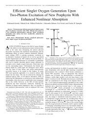
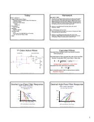
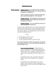
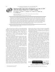
3) The signal from the transformer is rectified <strong>and</strong><br />
Vbulk<br />
<strong>Brute</strong> <strong>Force</strong> <strong>Power</strong> <strong>Supply</strong><br />
filtered by the “brute force” power supply (BFPS)<br />
board. Predict the expected peak voltage to ground<br />
of the output of the rectifier for both transformer<br />
settings. Predict the ripple of the filter output of BFPS ACin<br />
ACin<br />
for a 12 ohm load. Assume C_bulk (see figure) is a<br />
4.7mF filter capacitor <strong>and</strong> line input frequency of<br />
TP3 D1 D2 TP6<br />
60Hz. The marked TP connections are banana<br />
plugs connectors.<br />
Lab:<br />
Document your procedures (including drawing of the<br />
input, component, <strong>and</strong> probe connections) for<br />
D3 D4<br />
characterizing the I/V behavior of both a brute force<br />
<strong>and</strong> a regulated DC supply, as well as other<br />
0<br />
0<br />
parameters. You will design the two power supplies to give the same output voltages (for<br />
small loads). FOR ALL STEPS, SHOW WORK AND DOCUMENT DATA WITH TABLES<br />
AND PLOTS, as appropriate. Always keep transformer off when adjusting wires or<br />
connecting probes to the PCB.<br />
Most of the circuits are on a pre-fabricated printed circuit board (PCB) with sub-circuits that<br />
make up the regulated <strong>and</strong> unregulated circuits you will examine. There is also a 0.1<br />
current detect resistor on the PCB. See pspice layout <strong>and</strong> board layout of the PCB. The data<br />
sheet for the LM<strong>723</strong> provides information on sizing of divider resistors. It can be found in print<br />
at each station or at http://cache.national.com/ds/LM/LM<strong>723</strong>.pdf.<br />
1) Measure rms voltages of the two AC outputs of the transformers with a DVM. Do they<br />
match pre-lab predictions? Calculate the voltage peak to peak of the two AC outputs?<br />
2) Get a PCB <strong>and</strong> test the BFPS with relatively high impedance load (250 ohm variable load<br />
resistor) connected to V_bulk. Connect up circuit to transformer. Measure V_bulk with DVM<br />
<strong>and</strong> the voltage ripple with the scope for BOTH transformer settings with a 250 ohm load.<br />
Lab Exercise 5 Page 1 of 2<br />
1<br />
1<br />
1<br />
TP2<br />
C1<br />
Cbulk
Laboratory Electronics II Spring 2011<br />
PHSX262<br />
3) Use the lower (1:20) transformer voltage setting for this step. Set up the current sense<br />
resistor in series with the variable load resistance, with the current sense resistor nearer to<br />
ground. Vary load resistance from 250 ohms on down <strong>and</strong> as you do measure V_bulk <strong>and</strong><br />
voltage across sense resistor with the DVM <strong>and</strong> V_ripple (peak to peak ripple voltage) with<br />
the scope. Do not exceed more than 750mA output current (or fuse will blow). Record<br />
a representative screen capture of the ripple at around 750mA.<br />
Convert V_ripple into a percentage ripple. Record enough settings to get a smooth curve of<br />
V_bulk <strong>and</strong> percent ripple versus output current. Does percentage ripple curve match theory?<br />
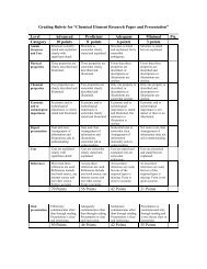
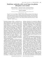
4) Connect up <strong>723</strong> power regulator.<br />
Vbulk is the input, Vcc. Choose resistors<br />
R2 <strong>and</strong> R3 that will make Vreg equal to<br />
maximum Vbulk you measured from 1:20<br />
transformer setting. From data sheet,<br />
what is the minimum Vcc needed to run<br />
the LM<strong>723</strong> regulator at this Vreg? Why?<br />
Which transformer setting will you need<br />
to use get sufficient Vcc? Set up<br />
regulator with chosen R2 <strong>and</strong> R3 <strong>and</strong><br />
proper transformer setting. Again have<br />
load include the 0.1 ohm current sense<br />
resistor <strong>and</strong> use DVM to alternate<br />
between measuring V_reg <strong>and</strong> voltage<br />
across current sense resister. Vary load<br />
resistance from 250 ohms on down. Do<br />
not exceed 700mA output current or<br />
go below 2 Vdc output voltages. Use<br />
Vz<br />
scope measure peak to peak voltage of ripples of V_reg <strong>and</strong> V_cc. Record enough settings<br />
to get a smooth curve of V_bulk <strong>and</strong> V_ripple versus output current. What would you<br />
estimate the minimum ripple rejection to be (in dB)? Is your estimate consistent with the<br />
specifications for <strong>723</strong>?<br />
5) Measure V_ref <strong>and</strong> compare with specifications sheet.<br />
6) What is V_reg <strong>and</strong> V_out for 250mA load current? Does that make sense?<br />
7) Based on the value specified for R1 (Rcl) in the schematic above, what is the expected<br />
current limit for this regulator?<br />
Conclusion:<br />
1. Compute normalized IV data for both the BFPS <strong>and</strong> the <strong>723</strong> regulated circuits, where<br />
i_norm = i_out/i_max <strong>and</strong> v_norm=v_out/v_max. Plot the normalized IV curves as y-<br />
axis on a linear graph with the actual output voltage as the horizontal axis. Label the<br />
constant current <strong>and</strong> constant voltage regions on the IV curve for the regulated supply.<br />
2. On a second graph, plot the measured percentage AC ripple as a function of output<br />
current for both supplies.<br />
3. Compare <strong>and</strong> contrast the two supplies.<br />
10<br />
9<br />
VOUT<br />
VZ<br />
Vout<br />
LM<strong>723</strong><br />
LM<strong>723</strong> <strong>Regulator</strong><br />
U1<br />
5<br />
4<br />
COMP 13<br />
6<br />
VREF<br />
ILIM 2<br />
ISENSE 3<br />
VC 11<br />
12<br />
V+<br />
7<br />
V-<br />
Vref<br />
0<br />
C2<br />
1n<br />
Vilim<br />
IN+<br />
IN-<br />
Vin-<br />
Q1<br />
TIP31<br />
Rcl<br />
Vcc<br />
1<br />
R2<br />
TBD<br />
R3<br />
TBD<br />
TP1<br />
Pass<br />
Trans<br />
R1<br />
1.5<br />
10W, 10%<br />
0<br />
Vreg<br />
1<br />
GND<br />
1<br />
TP5<br />
TP7<br />
Lab Exercise 5 Page 2 of 2