Practical Uses and Applications of Electro-Optic Modulators
Practical Uses and Applications of Electro-Optic Modulators
Practical Uses and Applications of Electro-Optic Modulators
You also want an ePaper? Increase the reach of your titles
YUMPU automatically turns print PDFs into web optimized ePapers that Google loves.
loss between the fiber pigtails <strong>and</strong> the modulator, as<br />
well as the loss in the modulator itself. Insertion loss<br />
should be in the range <strong>of</strong> 4–7 dB. Additional loss may<br />
occur, depending on the method used to couple light<br />
into the fiber pigtails.<br />
Working with Integrated-<strong>Optic</strong> <strong>Modulators</strong><br />
Note: When working with integrated-optic modulators, be aware <strong>of</strong> all<br />
manufacturer-specified safe operating levels. Exceeding the maximum<br />
electrical voltages or optical power can result in permanent<br />
damage to your modulator.<br />
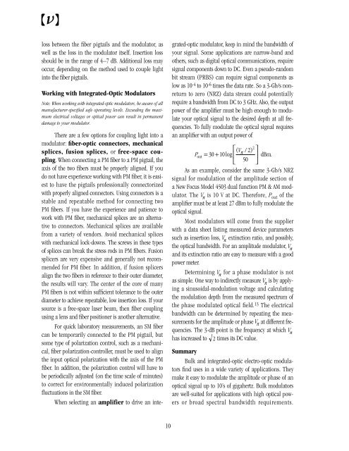
There are a few options for coupling light into a<br />
modulator: fiber-optic connectors, mechanical<br />
splices, fusion splices, or free-space coupling.<br />
When connecting a PM fiber to a PM pigtail, the<br />
axis <strong>of</strong> the two fibers must be properly aligned. If you<br />
do not have experience working with PM fiber, it is easiest<br />
to have the pigtails pr<strong>of</strong>essionally connectorized<br />
with properly aligned connectors. Using connectors is a<br />
stable <strong>and</strong> repeatable method for connecting two<br />
PM fibers. If you have the experience <strong>and</strong> patience to<br />
work with PM fiber, mechanical splices are an alternative<br />
to connectors. Mechanical splices are available<br />
from a variety <strong>of</strong> vendors. Avoid mechanical splices<br />
with mechanical lock-downs. The screws in these types<br />
<strong>of</strong> splices can break the stress rods in PM fibers. Fusion<br />
splicers are very expensive <strong>and</strong> generally not recommended<br />
for PM fiber. In addition, if fusion splicers<br />
align the two fibers in reference to their outer diameter,<br />
the results will vary. The center <strong>of</strong> the core <strong>of</strong> many<br />
PM fibers is not within sufficient tolerance to the outer<br />
diameter to achieve repeatable, low insertion loss. If your<br />
source is a free-space laser beam, then fiber coupling<br />
using a lens <strong>and</strong> fiber positioner is another alternative.<br />
For quick laboratory measurements, an SM fiber<br />
can be temporarily connected to the PM pigtail, but<br />
some type <strong>of</strong> polarization control, such as a mechanical,<br />
fiber polarization-controller, must be used to align<br />
the input optical polarization with the axis <strong>of</strong> the PM<br />
fiber. In addition, the polarization control will have to<br />
be periodically adjusted (on the time scale <strong>of</strong> minutes)<br />
to correct for environmentally induced polarization<br />
fluctuations in the SM fiber.<br />
When selecting an amplifier to drive an integrated-optic<br />
modulator, keep in mind the b<strong>and</strong>width <strong>of</strong><br />
your signal. Some applications are narrow-b<strong>and</strong> <strong>and</strong><br />
others, such as digital optical communications, require<br />
signal components down to DC. Even a pseudo-r<strong>and</strong>om<br />
bit stream (PRBS) can require signal components as<br />
low as 10 -4 to 10 -6 times the data rate. So a 3-Gb/s nonreturn<br />
to zero (NRZ) data stream could potentially<br />
require a b<strong>and</strong>width from DC to 3 GHz. Also, the output<br />
power <strong>of</strong> the amplifier must be high enough to modulate<br />
your optical signal to the desired depth at all frequencies.<br />
To fully modulate the optical signal requires<br />
an amplifier with an output power <strong>of</strong><br />
( )<br />
⎡ 2<br />
V ⎤<br />
π 2<br />
P = 30 + 10 log ⎢<br />
( / ) out<br />
⎥ dBm.<br />
⎣ 50 ⎦<br />
As an example, consider the same 3-Gb/s NRZ<br />
signal for modulation <strong>of</strong> the amplitude section <strong>of</strong><br />
a New Focus Model 4503 dual function PM & AM modulator.<br />
The V π is 10 V at DC. Therefore, P out <strong>of</strong> the<br />
amplifier must be at least 27 dBm to fully modulate the<br />
optical signal.<br />
Most modulators will come from the supplier<br />
with a data sheet listing measured device parameters<br />
such as insertion loss, V π extinction ratio, <strong>and</strong> possibly,<br />
the optical b<strong>and</strong>width. For an amplitude modulator, V π<br />
<strong>and</strong> its extinction ratio are easy to measure with a good<br />
power meter.<br />
Determining V π<br />
for a phase modulator is not<br />
as simple. One way to indirectly measure V π<br />
is by applying<br />
a sinusoidal-modulation voltage <strong>and</strong> calculating<br />
the modulation depth from the measured spectrum <strong>of</strong><br />
the phase modulated optical field. 13 The electrical<br />
b<strong>and</strong>width can be determined by repeating the measurements<br />
for the amplitude or phase V π at different frequencies.<br />
The 3-dB point is the frequency at which V π<br />
has increased to 2 times its DC value.<br />
Summary<br />
Bulk <strong>and</strong> integrated-optic electro-optic modulators<br />
find uses in a wide variety <strong>of</strong> applications. They<br />
make it easy to modulate the amplitude or phase <strong>of</strong> an<br />
optical signal up to 10’s <strong>of</strong> gigahertz. Bulk modulators<br />
are well-suited for applications with high optical powers<br />
or broad spectral b<strong>and</strong>width requirements.<br />
10


