DAP meter calibration DAP meter calibration - SEPR
DAP meter calibration DAP meter calibration - SEPR
DAP meter calibration DAP meter calibration - SEPR

You also want an ePaper? Increase the reach of your titles
YUMPU automatically turns print PDFs into web optimized ePapers that Google loves.
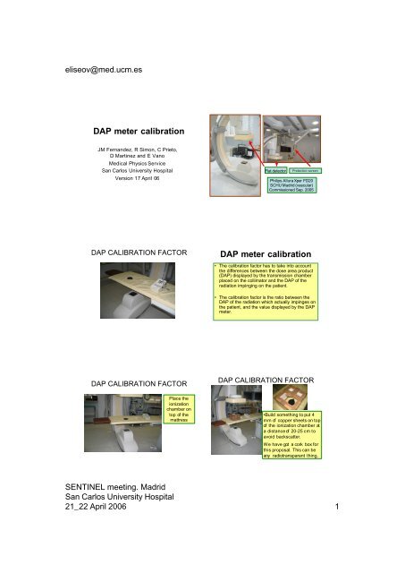
eliseov@med.ucm.es<br />
<strong>DAP</strong> <strong>meter</strong> <strong>calibration</strong><br />
JM Fernandez, R Simon, C Prieto,<br />
D Martinez and E Vano<br />
Medical Physics Service<br />
San Carlos University Hospital<br />
Version 17 April 06<br />
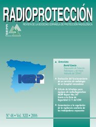
Flat detector<br />
Protection screen<br />
Philips AlluraXper FD20<br />
SCHU Madrid (vascular)<br />
Commissioned Sep. 2005<br />
<strong>DAP</strong> CALIBRATION FACTOR<br />
<strong>DAP</strong> <strong>meter</strong> <strong>calibration</strong><br />
• The <strong>calibration</strong> factor has to take into account<br />
the differences between the dose area product<br />
(<strong>DAP</strong>) displayed by the transmission chamber<br />
placed on the collimator and the <strong>DAP</strong> of the<br />
radiation impinging on the patient.<br />
• The <strong>calibration</strong> factor is the ratio between the<br />
<strong>DAP</strong> of the radiation which actually impinges on<br />
the patient, and the value displayed by the <strong>DAP</strong><br />
<strong>meter</strong>.<br />
<strong>DAP</strong> CALIBRATION FACTOR<br />
<strong>DAP</strong> CALIBRATION FACTOR<br />
Place the<br />
ionization<br />
chamber on<br />
top of the<br />
mattress<br />
•Build something toput 4<br />
mm of copper sheets on top<br />
of the ionization chamber at<br />
a distanceof 20-25 cm to<br />
avoid backscatter.<br />
We have got a cork box for<br />
this proposal. This can be<br />
any radiotransparent thing.<br />
SENTINEL meeting. Madrid<br />
San Carlos University Hospital<br />
21_22 April 2006 1
eliseov@med.ucm.es<br />
<strong>DAP</strong> CALIBRATION FACTOR<br />
<strong>DAP</strong> CALIBRATION FACTOR<br />
• Select the automatic<br />
fluoroscopy mode used more<br />
frequently in clinical practice.<br />
If the equipment has a<br />
device that automatically<br />
inserts copper filters, select<br />
the one which does not<br />
include anyone (typically<br />
high fluoroscopy mode).<br />
•Select a medium field size (i.e.<br />
23 cm) and put the chamber in<br />
the centre of the field.<br />
•Collimate the radiation field<br />
size to include the ionization<br />
chamber and avoid direct<br />
irradiation of the image<br />
intensifier or flat panel.<br />
<strong>DAP</strong> CALIBRATION FACTOR<br />
• With the help of the<br />
copper sheets and the<br />
distance focus - intensifier<br />
set the voltage to 80 kV<br />
•Maintain fluoroscopy until<br />
the system accumulates a<br />
<strong>DAP</strong> around 10 Gy cm 2<br />
•Record the accumulated<br />
dose with the reference<br />
ionisation chamber D ref<br />
and the <strong>DAP</strong> measured by<br />
the system.<br />
<strong>DAP</strong> CALIBRATION FACTOR<br />
So, we have to take notes of:<br />
• <strong>DAP</strong> i Initial Dose Area Product, from the X- Ray<br />
System before irradiation<br />
• <strong>DAP</strong> f Final Dose Area Product, from the X- Ray<br />
System after irradiation<br />
• D ref accumulated dose, from the ionization<br />
chamber<br />
<strong>DAP</strong> i = 5051 mGycm 2<br />
<strong>DAP</strong> f = 9678 mGycm 2<br />
D ref = 19.78 mGy<br />
<strong>DAP</strong> CALIBRATION FACTOR<br />
If we havethe possibility<br />
tomeasure the area with<br />
a slow film, we place it<br />
on top or in the place of<br />
the ionization chamber<br />
and irradiateit.<br />
Be careful not tochange<br />
any distance or size field<br />
<strong>DAP</strong> CALIBRATION FACTOR<br />
Calculating the area<br />
WITH THE SLOW FILM<br />
• Just calculatethe area of<br />
the impressed figure<br />
Ourarea was 185 cm2<br />
It is the easiest wayof not making a mistake<br />
SENTINEL meeting. Madrid<br />
San Carlos University Hospital<br />
21_22 April 2006 2
eliseov@med.ucm.es<br />
<strong>DAP</strong> CALIBRATION FACTOR<br />
Calculating the area<br />
FROM A PHOTO OF THE<br />
MONITOR<br />
• We havetoscalefrom a known<br />
distance<br />
i.e. this ionization chamber measures 9<br />
cmdia<strong>meter</strong>, so the area is 10 x 10.2 =<br />
102 cm 2<br />
Be careful! The field edges must appear in the<br />
monitor, if not , the area is probably bigger that the<br />
one we see.<br />
OBTAINING THE <strong>DAP</strong><br />
CALIBRATION FACTOR<br />
Now we haveall the necessary data, just replace in<br />
the formula:<br />
AD ⋅ Area<br />
f =<br />
<strong>DAP</strong> f<br />
− <strong>DAP</strong> i<br />
4.46 mGy 185 2<br />
⋅<br />
cm<br />
f<br />
=<br />
0 .78<br />
( 2361 1304<br />
2<br />
) =<br />
−<br />
mGy<br />
⋅<br />
cm<br />
INITIAL CHARACTERISATION OF<br />
THE SYSTEM<br />
INITIAL CHARACTERISATION<br />
OF THE SYSTEM<br />
•Place the ionization<br />
chamber on top of the<br />
matress<br />
•Put somePMMA to<br />
support the weight of<br />
another 20 cm on top<br />
of it without crushing<br />
the ionization chamber<br />
INITIAL CHARACTERISATION OF<br />
THE SYSTEM<br />
• Place 20 cm of<br />
PMMA on top of this.<br />
•Select the geometry<br />
to have the middle of<br />
the PMMA thickness in<br />
the isocenter.<br />
•Place the chamber in<br />
close contact with the<br />
PMMA<br />
INITIAL CHARACTERISATION OF<br />
THE SYSTEM<br />
• Maintain 5-6 cm<br />
between the PMMA and<br />
the entrance of the image<br />
intensifier or flat panel<br />
detector.<br />
• verify that the chamber<br />
is fully included in the<br />
selected field size.<br />
• Take note of ALL the<br />
relevant distances<br />
SENTINEL meeting. Madrid<br />
San Carlos University Hospital<br />
21_22 April 2006 3
70<br />
60<br />
50<br />
40<br />
30<br />
20<br />
10<br />
0<br />
3,3<br />
11,6<br />
6,1<br />
20,7<br />
11,1<br />
5,6<br />
19,6<br />
37,0<br />
9,7<br />
19,5<br />
low medium high<br />
32,2<br />
57,2<br />
16 cm PMMA 20 cm PMMA 24 cm PMMA 28 cm PMMA<br />
eliseov@med.ucm.es<br />
INITIAL CHARACTERISATION OF<br />
THE SYSTEM<br />
•FLUOROSCOPY MODES:<br />
Take note of the dose rate and radiographic<br />
technique<br />
mGy/min<br />
25<br />
20<br />
15<br />
10<br />
5<br />
0<br />
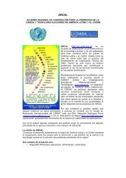
INITIAL CHARACTERISATION OF THE<br />
SYSTEM. EXAMPLES.<br />
4,3<br />
Entrance surface air kerma rate in different<br />
fluoroscopy modes and diferent field sizes.<br />
Philips Allura FD.HCSC<br />
20 cm PMMA<br />
5,1<br />
6,1<br />
7,8<br />
9,2<br />
11,1<br />
13,4<br />
16,0<br />
low medium high<br />
19,5<br />
Variation of the entrance<br />
surface air kerma with<br />
the field size in different<br />
fluoroscopy modes<br />
•ADQUISITION MODES<br />
Take note of the accumulated doseand the<br />
number of images made during the irradiation<br />
and obtain the dose per image<br />
mGy/min<br />
48 cm field 42 cm field 31 cm field<br />
Entrance surface air kerma rate in different<br />
fluoroscopy modes .<br />
Philips Allura FD. HCSC.<br />
31 cm field<br />
Variation of the<br />
entrancesurfaceair<br />
kerma with PMMA<br />
thickness in different<br />
fluoroscopy modes .<br />
INITIAL CHARACTERISATION OF<br />
THE SYSTEM. EXAMPLES.<br />
mGy/im<br />
7<br />
6<br />
5<br />
4<br />
3<br />
2<br />
1<br />
0<br />
Entrance surface air kerma per image in image<br />
adquisition for<br />
diferent field sizes.Philips Allura FD. HCSC.<br />
5,9 5,9<br />
5,0<br />
3,2<br />
2,4<br />
1,9<br />
1,0<br />
1,3<br />
0,5<br />
0,8<br />
0,2<br />
0,4<br />
16 cm PMMA 20 cm PMMA 24 cm PMMA 28 cm PMMA<br />
48 cm field 42 cm field 31 cm field<br />
Entrancesurface<br />
air kerma in<br />
different PMMA<br />
thickness andfield<br />
sizes in image<br />
adquisition<br />
Commissioned at the SCUH<br />
Madrid on September 2005<br />
MPPS (Modality Performed Procedure Step) working on<br />
18 October 2005 Philips Allura XPER – FD20<br />
MPPS (Modality Performed Procedure Step) working<br />
on 18 October 2005 Philips Allura XPER – FD20<br />
• Operation Received = N- CREATE<br />
• (0008,0060) : Modality: XA<br />
• (0010,0010) : Patient's Name: CLINICO SAN CARLOS<br />
• (0010,0020) : Patient ID : 1234<br />
• (0018,115E) : Image Area Dose Product: 82.23<br />
• (0040,0250) : Performed Procedure Step End D: 18/10/2005<br />
• (0040,0251) : Performed Procedure Step End T: 14:05:01<br />
• (0040,0300) : Total Time of Fluoroscopy: 14<br />
• (0040,0301) : Total Number of Exposures: 11<br />
• (0040,0302) : Entrance Dose: 1<br />
• (0040,0340) : Performed Series Sequence:<br />
• (0040,8302) : Entrance Dose in mGy: 75.461433<br />
SENTINEL meeting. Madrid<br />
San Carlos University Hospital<br />
21_22 April 2006 4
eliseov@med.ucm.es<br />
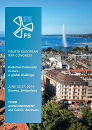
Examples of slow films (Kodak EDR2) used to audit skin<br />
dose distribution during interventional vascular procedures<br />
SENTINEL meeting. Madrid<br />
San Carlos University Hospital<br />
21_22 April 2006 5