MT Express Sample Low Resolution Issue ... - Monitoring Times
MT Express Sample Low Resolution Issue ... - Monitoring Times
MT Express Sample Low Resolution Issue ... - Monitoring Times

Create successful ePaper yourself
Turn your PDF publications into a flip-book with our unique Google optimized e-Paper software.
RADIO RESTORATIONS<br />
BRINGING OLD RADIOS BACK TO LIFE<br />
Marc Ellis<br />
marcellis@monitoringtimes.com<br />
NC-57 Electronic Restoration Completed<br />
We finished the last NC-57 work session<br />
with about half of the capacitors<br />
replaced before I ran out of time<br />
and almost out of capacitors. There’s an unusual<br />
amount of bypassing in the various circuits, which<br />
is an indication of the excellent quality that was<br />
built into this fairly low-priced radio. I think I’ve<br />
already mentioned how impressed I was by the professional<br />
construction of this set as compared to the<br />
Hallicrafters S-40 (restored earlier in this column)<br />
– which had a similar price, but which was built<br />
more like a household broadcast receiver.<br />
❖ Mica or Paper?<br />
At any rate, with a fresh supply of capacitors<br />
on the bench, I went back to work and completed<br />
the job. This took quite a bit of time because of the<br />
tight construction of the radio, but the result was<br />
very satisfying. I know I’ve told you in the past<br />
about the disappointment some folks feel when they<br />
open up a recently-purchased receiver to find that<br />
all of the original paper caps have been replaced<br />
by modern equivalents. They feel that the radio<br />
has been somehow violated and, understandably,<br />
wonder if the circuitry has been changed, either<br />
deliberately or accidentally.<br />
However, I see a radio chassis with a complete<br />
set of meticulously-installed modern capacitors as a<br />
thing of beauty. (As long as it’s a set of capacitors<br />
that I put in!) I know that there’s an excellent chance<br />
that the radio can be aligned to perform like new. It<br />
should also give good service for many years without<br />
suffering a sudden and disastrous short circuit<br />
that might ruin hard-to-replace components.<br />
As you know, most of the paper capacitors in<br />
the NC-57 were Bakelite-cased units that look like<br />
mica caps, which hardly ever need to be replaced.<br />
However, as discussed last time, the Bakelite cased<br />
paper caps are no more to be trusted than the waxcovered<br />
tubular units. They all tested leaky on my<br />
capacitor checker. So it’s important that you find<br />
and replace any such units present in your restora-<br />
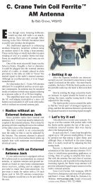
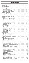
Fig. 1b. Six-dot coding pattern. See text for<br />
details.<br />
tion project.<br />
Generally, the Bakelite-cased paper caps<br />
look much larger than similarly-cased mica ones<br />
– which makes sense because their capacities are<br />
much larger. The paper caps, used as they are for<br />
bypass and coupling purposes, typically range from<br />
.01 to .1 uf. Mica units, often used in r.f. frequencydetermining<br />
circuits, might run from 10 to 500 pf<br />
(uuf).<br />
So, if in doubt about whether a capacitor is<br />
paper or mica, check its size and function in the<br />
circuit. Also check the parts list. The NC-57’s list<br />
helpfully indicates which caps are which.<br />
❖ Reading Capacitor Color<br />
codes<br />
The color codes used to identify Bakelitecased<br />
paper or mica caps can be confounding because<br />
so many versions have been used. Eventually<br />
the system was somewhat standardized by the RMA<br />
(Radio Manufacturer’s Association). Following are<br />
the more common styles.<br />
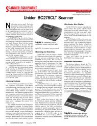
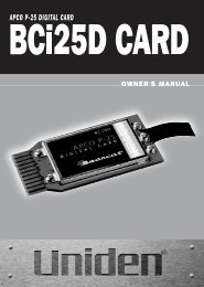
If the capacitor is the standard garden variety<br />
(500-volt; 20% tolerance) as found in most receivers,<br />
including the NC-57, then a simple row of three<br />
dots is used (Fig. 1a). Make sure you read along the<br />
row from left to right with the manufacturer’s name<br />
right side up or in the direction of the arrows.<br />
The first dot (A) is the first significant figure of<br />
the rating; the second (B) is the second significant<br />
figure; the third (C) tells how many zeros to add<br />
following the second figure to give the capacity<br />
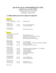
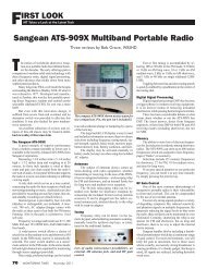
in pf (uuf). For the specific values to use for the<br />
different colors, see the table in Fig. 2. For mica<br />
capacitors, the capacity is usually left in uuf.<br />
However, the capacities of paper caps are usually<br />
so much larger that it they are converted to uf. This<br />
is simply a matter of moving the decimal point six<br />
places to the left.<br />
For example, a very common Bakelite-cased<br />
unit found in the NC-57 has a three-dot color code<br />
of brown-black-orange. Since it has just a 3-dot<br />
code, we know that it is a 500-volt, 20% tolerance<br />
unit. The first (black) and second (brown) significant<br />
figures are 1 and 0. The number of zeros after<br />
the significant figures is three (orange). So the<br />
capacity is 10000 (same as 10000.0, of course) pf<br />
(uuf) or – moving the decimal point six places to<br />
the left – .01 uf.<br />
You might sometimes see a row of five dots<br />
(less common and not illustrated). This format is<br />
used when voltage (fourth, or “D,” dot) and tolerance<br />
(fifth, or “E” dot) must be specified. See Fig.<br />
2 for the values associated with various colors of<br />
these dots. The fourth and fifth dot might be found,<br />
instead, on the rear of the capacitor or above the<br />
basic row of three.<br />
Finally, you might come across a capacitor<br />
coded with two rows of three dots (Fig. 1b). This<br />
might be (but see next paragraph) a unit with a capacity<br />
requiring three significant figures to express<br />
(let’s say 325 uuf, just to make up an example).<br />
For this unit, the top-row colors would be Orange-<br />
Red-Green. The third color (labeled “B1” in the<br />
figure) is read from column “B” in Fig. 2 (or the<br />
identical column “A.”) The number of zeros to be<br />
added (labeled “C” as before) is the last dot in the<br />
bottom row. In this case it would be brown. The<br />
first two dots in that row represent voltage (“D”)<br />
and tolerance (“E”).<br />
Just a few caveats! If you see a six-dot coding<br />
Fig. 1a. Two examples of three-dot coding. If no<br />
direction arrows are present, as at left, read the<br />
dots from left to right with the manufacturer’s<br />
name right side up.<br />
Fig. 2. Chart shows values corresponding to the various dot positions and colors.<br />
64 MONITORING TIMES January 2005