Create successful ePaper yourself
Turn your PDF publications into a flip-book with our unique Google optimized e-Paper software.
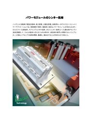
Modules – Explanations – SEMIPONT<br />
SEMIPONT ® , Bridge Rectifiers and AC<br />
controller<br />
Features<br />
• Various cases and configurations with diode and thyristor<br />
rectifiers, rectifier/brake chopper or AC controller<br />
• Compact plastic packages with screw, fast-on or PCBmountable<br />
lead terminals<br />
• High blocking voltages up to 1800 V, high surge currents:<br />
high ruggedness for hard industrial applications<br />
• High isolation voltage<br />
• Large, isolated baseplate (except some Miniature rectifier<br />
and SEMIPONT ® 5/6)<br />
• Some types of miniature rectifiers available with<br />
avalanche characteristics<br />
• Hard or soft moulded<br />
• UL recognized types available, e. g. File E 63532 for<br />
SEMIPONT ® 5/6<br />
• SEMIPONT ® 5/6: Bridge Rectifiers for PCB assembly<br />
with thermal pressure contact, base plate free for low<br />
thermal impedance, soft moulded<br />
• Integrated temperature sensor in SEMIPONT ® 6<br />
• Terminals of leadable bridges are available for wave<br />
soldering to PCB<br />
• Fast rectifier bridges including CAL-diodes<br />
For rectifier brigdes and AC controller in SEMITOP ® technology<br />
see chapter SEMITOP ® . For low power bridge rectifiers<br />
for consumer and less rugged applications see in<br />
chapter Low Power Rectifier.<br />
Principal configurations and cases<br />
Uncontrolled Bridges<br />
Case<br />
Connectors<br />
Footprint<br />
dimensions<br />
Miniature<br />
bridge rectifier,<br />
inline,<br />
wired<br />
Miniature rectifier<br />
with<br />
screw connectors<br />
Square bridge<br />
28,5x<br />
28,5mm 2 ,<br />
wired<br />
Diode<br />
bridge<br />
1 ~<br />
x<br />
x<br />
x<br />
Diode<br />
bridge<br />
3 ~<br />
Avalanche<br />
char. avail.<br />
(some types)<br />
x<br />
x<br />
Case<br />
Connectors<br />
Footprint<br />
dimensions<br />
Square<br />
bridge, fast-on<br />
connectors<br />
Rectangular<br />
bridge, PCB<br />
leadable connectors,<br />
63,5x<br />
29,5mm 2<br />
Rectangular<br />
x<br />
bridge, faston,<br />
80x29mm 2<br />
Square<br />
x x<br />
55x55mm 2<br />
bridge, screw<br />
conn.,<br />
Square<br />
x x<br />
71x71mm 2<br />
bridge, screw<br />
conn.,<br />
SEMIPONT 1,<br />
x<br />
fast- on,<br />
63x32mm 2<br />
SEMIPONT 2, x x<br />
65x48mm 2<br />
screw conn.,<br />
SEMIPONT 3, x x<br />
57x42 mm 2<br />
screw conn.,<br />
SEMIPONT 4,<br />
x<br />
screw conn.,<br />
94x54 mm 2<br />
SEMIPONT 5,<br />
x<br />
PCB leadable,<br />
81x45,6mm 2<br />
SEMIPONT 7,<br />
screw conn.,<br />
94x54mm 2<br />
x<br />
x<br />
Controllable Bridges, Bridges with Brake Chopper,<br />
AC Controller<br />
Case<br />
Connectors<br />
Footprint<br />
dimensions<br />
Square<br />
Bridge, screw<br />
conn., 71x<br />
71mm 2<br />
SEMIPONT 1,<br />
fast-on, 63x<br />
32mm 2<br />
Diode<br />
bridge<br />
1 ~<br />
controllable<br />
bridge<br />
1 ~<br />
x<br />
x<br />
Diode<br />
bridge<br />
3 ~<br />
x<br />
x<br />
controllable<br />
bridge<br />
3 ~<br />
Avalanche<br />
char. avail.<br />
(some types)<br />
3 ~ diodes<br />
with<br />
brake<br />
chopper<br />
AC<br />
controller<br />
3 ~<br />
136 Modules – Explanations – SEMIPONT 15-04-2005 © by SEMIKRON
Modules – Explanations – SEMIPONT<br />
Case<br />
Connectors<br />
Footprint<br />
dimensions<br />
SEMIPONT 2, x x<br />
65x 48mm 2<br />
screw conn.,<br />
SEMIPONT 5,<br />
x x<br />
81x 45,6mm 2<br />
PCB leadable,<br />
SEMIPONT 6,<br />
x<br />
PCB leadable,<br />
100x 44,6mm 2<br />
SEMIPONT 7,<br />
screw conn.,<br />
94x 54mm 2 x x<br />
Type Designation Systems<br />
Ambient rated miniature bridge rectifiers with pins for<br />
PCB<br />
<br />
SK B B 40 C 1000 L5B<br />
SEMIKRON component<br />
Bridge rectifier, single phase<br />
Two-pulse bridge circuit<br />
Recommended max. AC input voltage (V rms )<br />
Max. capacitive load current specified in datasheet<br />
Direct output current (freely suspended) (mA)<br />
pin out configuration<br />
Ambient rated miniature bridge rectifiers with screw<br />
terminals<br />
/ _ <br />
SK B B 250 / 220 _ 4<br />
SEMIKRON component<br />
Bridge rectifier (single phase)<br />
Two-pulse bridge circuit<br />
Recommended max. AC input voltage (V rms )<br />
Direct output voltage (R/L load) (V)<br />
Direct output current (freely suspended) (A)<br />
SKB a B... Avalanche types<br />
Case rated power input bridge rectifiers SEMIPONT ®<br />
/ _ <br />
SK DH 116 / 12 _ L100<br />
SEMIKRON component<br />
Circuit<br />
controllable<br />
bridge<br />
1 ~<br />
B: Single-phase bridge<br />
controllable<br />
bridge<br />
3 ~<br />
3 ~ diodes<br />
with<br />
brake<br />
chopper<br />
AC<br />
controller<br />
3 ~<br />
C: Single-phase bridge with freewheeling diode<br />
D: Three-phase bridge<br />
U: Three-phase AC controller W3C<br />
Functional circuit elements<br />
D: Diode bridge<br />
H: Half-controlled diode/thyristor bridge, common cathode<br />
T: Fully controlled thyristor circuit<br />
Direct output current (I D [A]), but SEMIPONT ® 5 and 6:<br />
(I D /10 [A])<br />
then last digit is SEMIPONT ® case size ("5"; or "6" )<br />
Voltage class (V DRM , V RRM / 100 [V])<br />
Special options:<br />
L: including IGBT brake or PFC chopper<br />
_xx Type current of the IGBT I C [A]<br />
Captions of the Figures<br />
Fig. 1 For ambient rated devices: Maximum rated direct<br />
output current I D against ambient temperature T a for resistive<br />
(R) and capacitive (C) loads<br />
Fig. 2 For ambient rated devices: Typical power dissipation<br />
P v against direct output current I D for resistive (R) and<br />
capacitive (C) loads<br />
Fig. 3<br />
Left: For case rated devices: Typical power dissipation P V<br />
against maximum direct current I D for resistive (R) and<br />
capacitive (C) loads<br />
Right: For case rated devices: case temperature T c<br />
against ambient temperature T a for various cooling conditions<br />
I: Freely suspended or mounted on an insulator<br />
M: Mounted on a painted metal sheet 250 x 250 x 1 mm 3<br />
P ... : Mounted on heatsink P ...<br />
P ... F: Mounted on heatsink P ... with forced air cooling.<br />
For a particular power dissipation P v on the left hand scale<br />
the corresponding case temperature T c is given by the<br />
right hand scale. Recommended current: I N = 0,8 I D<br />
Fig. 4<br />
Left: For case rated thyristor devices: Total power dissipation<br />
P VTOT of the bridge rectifier against direct output current<br />
I D for various conduction angles of the current through<br />
each thyristor (typical values)<br />
Right: For case rated thyristor devices: Case temperature<br />
T c against ambient temperature T a for various thermal<br />
resistances R th(c-a) case to ambient of the heatsinks (including<br />
contact thermal resistances R th(c-s) case to heatsink.<br />
For a particular power dissipation on the left vertical scale<br />
the corresponding case temperature is given by the right<br />
scale<br />
© by SEMIKRON 15-04-2005 Modules – Explanations – SEMIPONT 137
Modules – Explanations – SEMIPONT<br />
Fig. 5 For case rated power rectifiers: Ratio of the permissible<br />
overload current I T(OV) under fault conditions to the<br />
surge on-state current I TSM (or I FSM ) for 10 ms (50 Hz)<br />
against duration t of the overload (time t = 1 to 1000 ms).<br />
Parameter: Peak value of the reverse voltage applied between<br />
the on-state current pulses<br />
Fig. 6 Rated overload characteristic vs. time: Maximum<br />
direct output current I D for short time overload against<br />
duration of overload after operating the bridge at I N = 0,8<br />
I D for times t = 0,1 s to 10 min.<br />
Fig. 7 For avalanche diode devices: Rated reverse power<br />
dissipation. Allowable non-repetitive peak reverse power<br />
dissipation P RSM of the avalanche diode types against<br />
duration of reverse voltage surge time t = 1 µs to 0,1 s,<br />
during operation at I N = 0,8 I D or I NCL = 0,8 I DCL<br />
Fig. 8 For thyristor devices: Typical recovered charge Q rr<br />
against rate of decrease of on-state current -di F /dt at maximum<br />
virtual junction temperature. Parameter: on-state<br />
current before turn-off<br />
Fig. 9 Forward characteristics of a diode arm. Typical<br />
values<br />
Fig. 10 On-state characteristics of a thyristor arm. Typical<br />
values<br />
Fig. 11 Gate characteristic of a thyristor device: Gate<br />
voltage V G against gate current I G showing the region of<br />
possible (BMZ) and certain (BSZ) triggering for various virtual<br />
junction temperatures T vj . The current and voltage of<br />
the triggering pulse must lie in the region of certain triggering<br />
(BSZ), but the peak pulse power P G must not exceed<br />
that given for the pulse length tp used.The curve 20 V;<br />
20 Ω is the output characteristic of an adequate trigger<br />
equipment<br />
Fig. 12 Transient thermal impedance junction to case<br />
Z (th)j-c of a single thyristor (diode) against the time t elapsed<br />
after a step change in power dissipation. (For computing<br />
intermittend loads)<br />
Technical Explanations<br />
For the caption of all ratings und parameters please refer<br />
to chapters SEMIPACK ® and DISCRETE THYRISTORS<br />
AND DIODES or (for brake chopper IGBTs) the chapter<br />
SEMITRANS TM . Below are only the most important definitions<br />
for bridge rectifiers.<br />
a) Absolute maximum ratings<br />
Non-repetitive peak reverse voltage V RSM<br />
Maximum allowable peak value of single transient reverse<br />
voltages.<br />
Repetitive peak off-state and reverse voltages V DRM<br />
and V RRM<br />
Maximum allowable peak value of repetitive transient offstate<br />
and reverse voltages.<br />
Avalanche breakdown voltage V (BR)<br />
This value is given for avalanche types only (indicated in<br />
the type number by the letter "a"). At this value of reverse<br />
voltage the reverse current starts to increase rapidly.<br />
Reverse voltage peaks of short duration (< 10 µs) may<br />
exceed the avalanche voltage without causing damage,<br />
but if these peaks are of long duration or are repetitive,<br />
care must be taken that over-dissipation does not occur<br />
(see Fig.7 of those datasheets).<br />
Recommended alternating input voltage V VRMS<br />
This is the sinusoidal r.m.s. input voltage which may be<br />
used with due allowance made for voltage transients. An<br />
efficient transient suppressing network may still be required<br />
if the voltage transients are of excessive amplitude,<br />
duration or power.<br />
Maximum value of reservoir capacitor C max , and minimum<br />
value of surge limiting resistor R min with capacitive<br />
loads<br />
The values of the surge limiting resistor and the reservoir<br />
capacitor are limited by two requirements:<br />
a) when the current first is switched on, the amplitude and<br />
duration of the initial charging current should not over-load<br />
the rectifier, and<br />
b) the continuous current rating with a capacitive load I DCL<br />
should not be exceeded. This is determined by the form<br />
factor, which is dependent upon R min , C max and the load<br />
impedance. Taking account of the above conditions, the<br />
maximum value of reservoir capacitor is given by the following<br />
equation:<br />
C max = 10 7 * I D / f * V D<br />
where<br />
C max : capacitance of the reservoir capacitor in µF<br />
I D : direct output current in A<br />
V D : direct voltage across the capacitor in V<br />
f: operating frequency in Hz.<br />
The value for R min given in the datasheets includes the<br />
resistances of all components in the charging circuit of the<br />
reservoir capacitor. If a transformer is used which has an<br />
AC resistance of its windings R min , then no additional<br />
surge limiting resistor is required. In other cases the winding<br />
resistance may be deducted from R min to arrive at the<br />
value of resistance which should be used.<br />
R min = V VRMS / 1,6 * I FSM<br />
where<br />
R min : minimum value of surge limiting resistance in Ω<br />
V VRMS : open circuit alternating r.m.s. voltage in V<br />
I FSM : surge current rating of the bridge at maximum<br />
junction temperature in A<br />
138 Modules – Explanations – SEMIPONT 15-04-2005 © by SEMIKRON
Modules – Explanations – SEMIPONT<br />
Permissible overload current I (OV)<br />
The diagrams fig. 5 resp. fig. 6 (for small ambient rated<br />
devices) of the datasheet show the ratio of the highest permissible<br />
overload current I (OV) to the maximum steadystate<br />
output current I D or I DCL , resp., of the bridge rectifier<br />
freely suspended or mounted on an insulator (cooling<br />
mode "isolated"), against the duty cycle ED.<br />
Maximum direct output current I D , I DCL<br />
I D is the maximum direct output current of the complete<br />
rectifier bridge for the heatsink types and cooling conditions<br />
stated, with no margins allowed for overloads. I DCL is<br />
the I D with capacitive load. See also fig. 1 (for ambient<br />
rated devices) and fig. 3 (for case rated devices). In practical<br />
cases one should use only 80 % of these values (called<br />
the "recommended direct output current I N , I NCL "), so<br />
that short term overloads and small degradations in cooling<br />
conditions will not result in any damage.<br />
Single cycle surge forward current I FSM<br />
Maximum peak value of a single half sinewave current<br />
surge of 10 ms duration which will not cause damage.<br />
5 ms after this surge the reverse voltage may be allowed<br />
to rise to 2/3 of V RRM .<br />
i 2 t value<br />
This is the value of i 2 t, which should not be exceeded by<br />
any fuse used to protect against damage due to short circuits.<br />
The i 2 t rating of the fuse over the specified time interval<br />
should be less than the specified value of i 2 t of the rectifier.<br />
Temperatures T vj ; T stg ; T sold<br />
T vjm : maximum junction temperature, this may be exceeded<br />
only in case of a fault (I FSM )<br />
T stg : minimum and maximum storage temperature without<br />
applied voltage = max. operating temperature of the case<br />
T sold : maximum soldering temperature for the terminals<br />
during solder process. See assembly instructions.<br />
Isolation breakdown withstand voltage V isol<br />
Max. RMS or DC value between the isolated terminals and<br />
the baseplate, applied between the high potential terminals,<br />
all connected with each other, and the ground potential<br />
of the baseplate for a specified time at the final test procedure<br />
of the device. See chapter SEMIPACK, clause<br />
"Isolation".<br />
b) Characteristic values<br />
of the functional circuit elements included in the rectifier<br />
device, please refer to the relevant chapter as follows:<br />
For diode terms:<br />
V F ; V (TO) , r T ; R th(j-c) ; I RRM ; Q rr ; E off ; R th(j-s) refer to chapter<br />
Diodes<br />
For thyristor terms:<br />
V T ; V T(TO) ; r T ; R th(j-c) ; I GD ; V GT ; I GT ; I H ; I L ; (dv/dt) cr ; (di/dt) cr<br />
refer to chapter Thyristors<br />
For IGBT-terms:<br />
V CES ; V GES ; I C ; I CM ; V CEsat ; t d(on) ; t r ; t d(off) ; t f ; E on +E off ; C ies ;<br />
R th(j-c) refer to chapter SEMITRANS TM IGBT- modules<br />
Thermal resistance R th(j-a) ; R th(j-c) ; R th(c-s)<br />
R th(j-a) : thermal resistance junction to ambient air is specified<br />
for ambient rated devices for PCB mounting<br />
R th(j-c) : thermal resistance junction to case and<br />
R th(c-s) : thermal contact resistance case to heatsink are<br />
specified for case rated devices, for mounting on a heatsink.The<br />
main heat flow is through the base plate of the<br />
bridge rectifier, if the bridge rectifier is built for mounting on<br />
a heatsink. One must take careful note of the mounting<br />
instructions, see down below clause "assembly instructions".<br />
Temperature sensor R TS<br />
SEMIPONT ® 6 includes a temperature sensor as protective<br />
device, the resistance of which is specified for 25 °C<br />
and for another high temperature (100 °C).<br />
Application Notes<br />
ESD protection<br />
IGBT circuit (only in SEMIPONT ® 6) modules are sensitive<br />
to electrostatic charges. All SEMIPONT ® 6 modules are<br />
ESD protected in the shipment box with an ESD cover.<br />
During the modules handling and assembly, use conductive<br />
grounded wristlet and a conductive grounded working<br />
place.<br />
Isolation testing<br />
The isolation breakdown withstand voltage V isol between<br />
the live parts and the baseplate (resp. DBC substrate of<br />
SEMIPONT ® 5 and 6) of each SEMIKRON rectifier<br />
module is tested during the 100 % final routine test according<br />
to the datasheet specifications. For details on relevant<br />
international standards about the specifications of<br />
isolation withstand voltage V isol also for equipment (as<br />
IEC, EN; DIN, VDE, UL) see chapter SEMIPACK ® /Application<br />
notes.<br />
Selection of voltage class<br />
The table below shows the recommended selection<br />
voltage class V RRM to the nominal input line voltage V VN<br />
(examples).<br />
© by SEMIKRON 15-04-2005 Modules – Explanations – SEMIPONT 139
Modules – Explanations – SEMIPONT<br />
nom. AC-line voltage L-L recommended voltage<br />
class<br />
V VN / V<br />
V RRM , [V DRM ] / V<br />
60 200<br />
125 400<br />
250 800<br />
380 1200<br />
400 1400<br />
440 1400<br />
460 1600<br />
500 1600<br />
575 1800<br />
Transient voltage suppression<br />
Where only low-energy transients may occur, the snubber<br />
network recommended in the individual data sheets is sufficient.<br />
Alternatively, a varistor may be used in place of the<br />
RC network. For avalanche types with such transients no<br />
suppression network may be necessary. Where highenergy<br />
transients are to be expected, more efficient suppression<br />
networks should be used for both normal and<br />
avalanche types. It is recommended that the suppression<br />
network be connected across the d.c. terminals. Please<br />
note however that in the case of the controllable rectifiers<br />
the protective network must be fitted across each thyristor<br />
or the AC terminals in order that the suppression be effective<br />
when the thyristors are in the off-state. Where transients<br />
may occur on the DC side of the circuit, an additional<br />
suppression network is necessary.<br />
Over-current and short circuit protection<br />
Against damage by a short circuit appropriate semiconductor<br />
fuses should be applied between input terminals<br />
and mains.The i 2 t value of the fuses should be lower than<br />
the i 2 t value stated for the device.<br />
Thermal protection<br />
For ambient rated plastic encapsulated bridge rectifiers<br />
which are mounted by fixing bolts but which have no metal<br />
case or metal base plate, the thermal resistance R th(j-a)<br />
between the silicon chips and the ambient air is specified.<br />
It is valid for the device mounted onto an insulator, where<br />
heat dissipation via the connecting leads plays an<br />
important role. For this reason heavy leads should be<br />
used. Mounting this type of rectifiers on a metal plate<br />
results in only a very small reduction of the thermal resistance.<br />
With bridge rectifiers for PCB mounting the quoted<br />
thermal resistances R th(j-a) are valid for the rectifier seated<br />
tightly on to a PCB having tinned tracks 2 to 3 mm wide.<br />
Bridge rectifiers with long connecting wires can be spaced<br />
5 to 10 mm away from the PCB. This method of mounting<br />
will reduce the thermal resistance by 10 % or 15 % respectively<br />
due to the air cooling of the wires. Large area, tin plated<br />
PCB tracks can reduce the thermal resistance by 25 %<br />
to 30 %. In this case the rectifier must be seated directly<br />
on to the PCB. If the bridge rectifier is freely suspended by<br />
its leads from solder or screw terminals, a reduction of up<br />
to 20 % in thermal resistance can be expected. For case<br />
rated bridge rectifiers with metal base plate see also chapter<br />
SEMIPACK ® .<br />
In SEMIPONT ® 6 a temperature sensor is included. This<br />
sensor has R TS = 1000 Ω at 25 °C and 1670 Ω at 100 °C.<br />
If a specified value (for instance 100 °C) is overp assed, a<br />
signal should be formed to either set a warning or reduce<br />
power or switch the equipment off. For the value of measuring<br />
current SEMIKRON recommends 1 mA, the maximum<br />
values are 10 mA at 25 °C and 1 mA at 125 °C.<br />
Assembly instructions for ambient rated devices for<br />
PCB mounting<br />
Bridge rectifiers supplied with solder leads, resp. pins,<br />
should be soldered at iron or bath temperatures of 245 ±<br />
5 °C. The maximum allowable temperature is 255 °C f or<br />
5 s. Please take note of the interrelationship between<br />
mounting method and heat transfer given in the clause<br />
"thermal protection" further below. For more soldering<br />
details see also chapter Low Power Rectifiers.<br />
Assembly instructions for case rated devices<br />
In order to guarantee good thermal contact and to keep<br />
the thermal contact resistance values specified in the data<br />
sheets the contact area of the heatsink must be clean and<br />
free from particles. The unevenness remaining after grinding<br />
those areas must be less than 20 µm, the roughness<br />
less than 10 µm. The heatsinks used for devices with<br />
metal base plate devices must have a flat mounting surface.<br />
The metal base or the mounting surface of the case<br />
must be slightly coated with a heat conducting thermal<br />
compound paste, e.g. Wacker-Chemie P12. It is recommended<br />
to use a rubber roller, recommended thickness 30<br />
to 80 µm. A gauged manual torque spanner should be<br />
used, not an electric or compressed air tool. Flat and<br />
spring washers should always be used. Heatsinks must be<br />
mounted so, that their cooling fins are in line with the flow<br />
of cooling air. If possible mount the unit near the air inlet<br />
so that the air is not preheated. When the device is mounted<br />
on a chassis ensure that the chassis area is at least<br />
250 x 250 mm. If other items contribute to the heating of<br />
the chassis, it will need to be of greater area. In all cases<br />
check that the case temperature will never exceed that<br />
given in the rating diagram, see fig. 1, resp. fig. 3 (case<br />
rated devices). When devices are mounted on insulators,<br />
care must be taken again that the maximum allowable<br />
case temperature T c = T stgmax is not exceeded. The insulator<br />
must be able to withstand this maximum case temperature<br />
and, if this is not so, then the devices must be suspended<br />
on heat insulating distance washers.<br />
The table below shows the recommended mounting hardware<br />
for some case rated rectifier bridges, for which SEMI-<br />
KRON offers mounting hardware kits.<br />
140 Modules – Explanations – SEMIPONT 15-04-2005 © by SEMIKRON
Modules – Explanations – SEMIPONT<br />
contents SEMIPONT ® 2 SEMIPONT ® 2<br />
for 8 thyristor for 8 diode bridges<br />
bridges<br />
SEMIKRON- 33701500 32759000<br />
Ident-No.<br />
Baseplate screws 16 pcs. M5x16 16 pcs. M5x16<br />
Z4-1 DIN 7985- Z4-1 DIN 7985-<br />
8.8<br />
8.8<br />
Terminal screws 40 pcs. M5x8 Z4-<br />
1 DIN 7985-4.8<br />
Washers included on<br />
combi-screw<br />
Crincle washers included on<br />
combi-screw<br />
gate plugs 48 pcs. B2,8-1 for<br />
plug 2,8 x 0,8 mm<br />
plug f. aux. 48 pcs. 2,8 x 0,8<br />
cathode<br />
inside 5,1mm<br />
32409700<br />
insulating plug 48 pcs. 1-fold<br />
caps<br />
32769500<br />
40 pcs. M5x8 Z4-<br />
1 DIN 7985-4.8<br />
included<br />
combi-screw<br />
included<br />
combi-screw<br />
-<br />
-<br />
-<br />
on<br />
on<br />
9122-0072-40; fax +49-9122-9972-13; E-mail:<br />
kraus@dresselhaus.de homepage: www.dresselhaus.de<br />
Special assembly instructions for SEMIPONT ® 5 & 6<br />
Heat sink specification<br />
• The mounting area on the heatsink must be clean and<br />
free from grease and particles<br />
• Finger prints or discolorations on the bottom side do<br />
not affect the thermal behaviour<br />
The mechanical specifications for the heatsink are:<br />
• Flatness: 50 µm per 100 mm<br />
• Roughness R Z : 6,3 µm<br />
• Machined without overlaps<br />
contents SEMIPONT 3 SEMIPONT 4<br />
for 8 diode bridgeges<br />
for 4 diode brid-<br />
SEMIKRON- 33404200 33404300<br />
Ident-No.<br />
Baseplate screws 16 pcs. M5x16 8 pcs. M6x20 Z4-<br />
Z4-1 DIN 7984- 1 DIN 7985-8.8<br />
8.8<br />
Terminal screws 40 pcs. M5x12 20 pcs. M6x12<br />
Z4-1 DIN 7985- Z4-1 DIN 7985-<br />
4.8<br />
4.8<br />
Washers included on included on<br />
combi-screw combi-screw<br />
Crincle washers included on included on<br />
combi-screw combi-screw<br />
contents SKB 33, SKB/D 50 for 6<br />
bridges<br />
SEMIKRON-Ident-No. 33404400<br />
Baseplate screws 12 pcs. M4x8 Z4-1 DIN<br />
7985-4.8<br />
Terminal screws<br />
30 pcs. M5x10 Z4-1 DIN<br />
7985-4.8<br />
Washers<br />
included on combi-screw<br />
Crincle washers<br />
included on combi-screw<br />
gate plugs<br />
12 pcs. 13,5x4 for plug<br />
1,3mm<br />
Recommended: posidrive screws M...x... DIN 7985-...(Z4-<br />
1) (with captive crincle washers and washers) are also<br />
available from Muenchner Schraubenhandel, Dresselhaus<br />
KG., D-91126 Schwabach, Germany, Phone +49-<br />
Fig. 1 Heat sink surface specification<br />
Application of thermal grease<br />
In order to avoid air gaps at the interface between the<br />
module and the heat sink a thermal grease must be applied.<br />
The function of the grease is to flow according to the<br />
shape of the interface, allowing a metal-to-metal contact<br />
where it is possible, and filling the remaining gaps.<br />
Recommended thermal grease material is Wacker-Chemie<br />
P 12.<br />
SEMIKRON recommends to use an hard rubber roller or a<br />
screen print for an even distribution of the grease.<br />
The thickness of the applied grease layer should be:<br />
Module<br />
Thermal Grease (Wacker<br />
P12) Thickness<br />
SEMIPONT ® 5 50 - 55 µm<br />
SEMIPONT ® 6 50 - 55 µm<br />
The thickness of the applied grease can be checked by a<br />
measuring gauge (e.g. Company ELCOMETER Instruments<br />
GmbH, Himmlingstr. 18, 73434 Aalen, Tel. +49-<br />
7366-919283: Sechseck-Kamm 5 - 150 µm).<br />
Assembly on heatsink<br />
After applying the recommended thickness of thermal<br />
grease on the heatsink, tighten the screws applying first a<br />
0,5 Nm torque to each one, in order to lean the module<br />
against the heatsink, and then tighten each screw with the<br />
corresponding mounting torque:<br />
© by SEMIKRON 15-04-2005 Modules – Explanations – SEMIPONT 141
Modules – Explanations – SEMIPONT<br />
Module<br />
SEMIPONT ®<br />
5<br />
SEMIPONT ®<br />
6<br />
Mounting<br />
Torque<br />
2,5 Nm<br />
+0/-10%<br />
3 Nm<br />
+15/-15%<br />
SEMIKRON recommends:<br />
Screw<br />
• To use a torque wrench with automatic control;<br />
• To tighten the screws only once. After the mounting do<br />
not re-tighten the screws to the nominal mounting torque<br />
value. Due to relaxation of the housing and flow of<br />
thermal paste, the loosening torque is lower than the<br />
mounting torque. However the construction of the housing,<br />
the washers and the adhesion of the thermal<br />
paste still ensure sufficient thermal coupling of the<br />
module to the heatsink.<br />
• Do not exceed the mounting torque because a further<br />
increase of the maximum mounting torque will not<br />
improve the thermal contact but could only damage the<br />
module.<br />
Connections SEMIPONT ® 5 & 6 - PCB<br />
Washer<br />
DIN 912-M- DIN 6798<br />
4x20 Form A + DIN<br />
125<br />
DIN 912-M- DIN 6798<br />
4x20 Form A + DIN<br />
125<br />
The PCB has to be placed on the plastic posts present in<br />
each corner on the top of the SEMIPONT 5&6 modules<br />
(fig. 2).<br />
The module could be additionally fixed to the PCB by<br />
means of UNI EN ISO 7049 M2,9 self tapping screws.<br />
The maximum penetration depth must not exceed 6 mm.<br />
The minimum penetration depth has to be 4 mm.<br />
In order to avoid mechanical stress to the solder pins, the<br />
PCB has to be additionally supported (e.g. using spacers).<br />
• Wave soldering process<br />
• Selective soldering<br />
Independent of the soldering process used to solder<br />
SEMIPONT ® 5 & 6 modules to the PCB, SEMIKRON<br />
recommends a thorough evaluation of the solder joints to<br />
ensure an optimal connection between power module and<br />
the PCB.<br />
The time required to create a robust connection depend<br />
on several parameters:<br />
a) PCB thickness: When increasing the PCB thickness,<br />
the heat dissipation capability of the PCB itself will be the<br />
higher, and thus it will require a longer soldering time.<br />
b) Copper wire area: Pins require large copper wire to<br />
minimize resistive power losses during the current flowing.<br />
Since copper has a good heat transmission coefficient, the<br />
size of these copper wires directly affects the soldering<br />
time necessary to heat the PCB pad.<br />
c) Hand iron power: power, tip size and working temperature<br />
of the hand iron affect the soldering time. These<br />
parameters have to be adjusted in order to keep the maximum<br />
temperature within the specified limit.<br />
SEMIKRON recommends that the soldering joints should<br />
be thoroughly checked to ensure a high quality soldering<br />
joint. If necessary, different parameters should be adjusted<br />
in order to optimise the process.<br />
Hand Soldering<br />
SEMIKRON recommends to not exceed the maximum<br />
temperature of 260 °C for a soldering time of 10 se conds.<br />
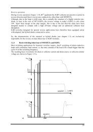
Wave Soldering Profile<br />
SEMIKRON recommends:<br />
• Do not exceed the maximum wave soldering profile of<br />
figure 3<br />
• The maximum preheating temperature has to be kept<br />
under or equal to the maximum storage temperature<br />
(125 °C)<br />
• Do not exceed the maximum preheating time of<br />
100 seconds<br />
• During the soldering phase, do not exceed the maximum<br />
soldering time of 10 seconds at the maximum<br />
temperature of 260 °C.<br />
Fig. 2 Mounting post details<br />
The suggested hole diameter for the soldering signal and<br />
power pins in the PCB is 2mm.<br />
Soldering on PCB<br />
SEMIPONT ® 5 & 6 modules could be soldered to the PCB<br />
using the most common soldering process:<br />
• Hand iron<br />
Post for PCB connections<br />
142 Modules – Explanations – SEMIPONT 15-04-2005 © by SEMIKRON
Modules – Explanations – SEMIPONT<br />
Fig. 3 Wave soldering profile<br />
© by SEMIKRON 15-04-2005 Modules – Explanations – SEMIPONT 143