Application Note - Semikron
Application Note - Semikron
Application Note - Semikron

You also want an ePaper? Increase the reach of your titles
YUMPU automatically turns print PDFs into web optimized ePapers that Google loves.
<strong>Application</strong> <strong>Note</strong> AN-11001<br />
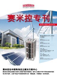
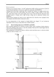
Fig. 20: 2L configurations to set up a 3L NPC module<br />
T1 D1<br />
T1 D1<br />
GAR<br />
T1<br />
D5 T2 D2<br />
GB<br />
D5 T2 D2 D5<br />
GA<br />
T2<br />
GB<br />
D6<br />
GB<br />
T3 D3 D6 T3 D3 D6<br />
GA<br />
T3<br />
GAL<br />
T4 D4<br />
T4 D4<br />
T4<br />
GB<br />
D1<br />
GA<br />
D2<br />
GA<br />
D3<br />
GA<br />
D4<br />
GA<br />
SEMIKRON 3L modules<br />
SEMIKRON provides a number of 3L modules that have<br />
been specially redesigned to minimize stray inductance.<br />
The module range starts with SEMITOP at a rated chip<br />
current of 20A to 150A followed by MiniSKiiP (75A -<br />
200A) up to SKiM modules with 200A - 600A rated<br />
current. While SEMITOP and MiniSKiiP are available for<br />
DC-link voltages of up to approx. 800V, SKiM modules<br />
allow for up to 1500V. The output power range goes as<br />
far as 250kVA (Fig. 22).<br />
As soon as even higher power is required several<br />
modules need to be connected in parallel.<br />
Fig. 22: SEMIKRON 3L module portfolio<br />
SEMITOP 3 & 4<br />
In the TNPC setup from 2L modules (Fig. 21) every<br />
commutation path is across module borders. Similar to<br />
the NPC setup stray inductances lead to high voltage<br />
overshoots which make this solution unattractive.<br />
TNPC:<br />
20 A – 150A<br />
MiniSKiiP 2 & 3<br />
75A – 200A<br />
Fig. 21: 2L configurations to set up a 3L TNPC module<br />
SKiM 4<br />
T1<br />
D1<br />
T1<br />
D1<br />
200A – 600A<br />
D2<br />
T3<br />
D2<br />
T3<br />
GA<br />
5 25 60 80 250 [kVA]<br />
GM<br />
T2<br />
D3<br />
T4<br />
D4<br />
GB<br />
GA<br />
T2<br />
GA<br />
D3<br />
T4<br />
D4<br />
GA<br />
The major benefit of the 1200V NPC module is that a<br />
maximum AC output voltage of 1000V can be realised at<br />
1500V DC-link. So it is possible to stay right within the<br />
low voltage directive (harmonised standards apply) on<br />
the one hand and reduce the converter current on the<br />
other without a change to the output power.<br />
Dedicated 3L modules<br />
As the 3L topology setup from 2L modules appears not to<br />
be the best solution a new module design has been<br />
made facing the special requirements coming with the 3L<br />
technology.<br />
At the very beginning a choice must be made concerning<br />
the module size and the related electric module power:<br />
the bigger the module shall become the more power it<br />
can provide as large chip area is available. Unfortunately<br />
larger module size also stands for higher stray<br />
inductances leading to high switching voltage overshoots<br />
thus limiting the maximum current.<br />
High power can either be realized by one large module or<br />
by many smaller modules in parallel. The latter solution<br />
requires an equally high number of driving units that<br />
need to be parallelized (with known problems: cost,<br />
space, jitter of separate drivers, compensation current<br />
when using paralleled drivers…).<br />
Driving 3L devices<br />
Normal operation sequences<br />
NPC:<br />
When all devices are switched off and the NPC converter<br />
starts operation it must be one of the inner IGBTs to be<br />
switched on first. In case of positive output voltage that is<br />
T2. After a short while (when T2 is entirely switched on)<br />
T1 may be pulsed. For the switch-off sequence the<br />
reverse order must be maintained: it must be made sure<br />
that T1 is thoroughly switched off before T2 may be<br />
turned off. That can be achieved by turning off T2 a short<br />
time (1..3µs) after the turn-off signal for T1 has occurred;<br />
this dead time is well known as interlock-time between<br />
TOP and BOT switch at SEMIKRON 2L gate drivers.<br />
© by SEMIKRON<br />
2012-09-03 – Rev04<br />
7 / 12