Application Note - Semikron
Application Note - Semikron
Application Note - Semikron

You also want an ePaper? Increase the reach of your titles
YUMPU automatically turns print PDFs into web optimized ePapers that Google loves.
<strong>Application</strong> <strong>Note</strong> AN-11001<br />
Fig. 10: Long commutation path in operating area 2<br />
Fig. 13: Operating area 3<br />
DC+<br />
VDC/2<br />
N<br />
VDC/2<br />
DC-<br />
D5<br />
D6<br />
T1<br />
T2<br />
T3<br />
T4<br />
D1<br />
D2<br />
AC<br />
D3<br />
D4<br />
IAC<br />
2.<br />
DC+<br />
VDC/2<br />
N<br />
VDC/2<br />
This commutation across the entire device is due to the<br />
fact that in operating area 2 (Fig. 11) the current is still<br />
positive (flowing from the DC-link towards the load) while<br />
the output voltage is negative.<br />
Fig. 11: Operating area 2<br />
<br />
0 .9<br />
i ( t )<br />
u ( t )<br />
0 .9<br />
V > 0<br />
I < 0<br />
D5<br />
D6<br />
T1<br />
T2<br />
T3<br />
T4<br />
D1<br />
D2<br />
AC<br />
D3<br />
D4<br />
IAC<br />
V > 0<br />
I > 0<br />
Voltage V<br />
Current I<br />
V > 0<br />
I < 0<br />
4 1<br />
3<br />
4 1<br />
0 t<br />
0<br />
)<br />
x<br />
V < 0<br />
I < 0<br />
The long commutation path for negative current (Fig. 14)<br />
goes back and forth between D6/T3 in the lower half of<br />
the module and D1/D2 in the upper half across the entire<br />
device.<br />
Fig. 14: Long commutation path in operating area 4<br />
DC+<br />
VDC/2<br />
D5<br />
T1<br />
D1<br />
4.<br />
DC+<br />
VDC/2<br />
D5<br />
T1<br />
D1<br />
V > 0<br />
I > 0<br />
VoltageV<br />
Current I<br />
U<br />
I<br />
1<br />
( x )<br />
( x )<br />
V < 0<br />
I > 0<br />
V < 0<br />
I < 0<br />
V > 0<br />
I < 0<br />
N<br />
V > 0<br />
I > 0<br />
D6<br />
T2<br />
T3<br />
D2<br />
AC<br />
D3<br />
IAC<br />
N<br />
D6<br />
T2<br />
T3<br />
D2<br />
AC<br />
D3<br />
IAC<br />
<br />
1<br />
0<br />
2 3<br />
4 1<br />
VDC/2<br />
T4<br />
D4<br />
VDC/2<br />
DC-<br />
DC-<br />
T4<br />
D4<br />
t<br />
3 <br />
The other short commutation path is active in operating<br />
area 3 (Fig. 12 & Fig. 13), in the lower half of the module.<br />
Output current and voltage are negative.<br />
Fig. 12: Short commutation path in operating area 3<br />
The long commutation in operating area 4 (Fig. 4) comes<br />
with negative output current (flowing from the AC<br />
terminal towards the DC-link) and positive voltage.<br />
Fig. 15: Operating area 4<br />
DC+<br />
VDC/2<br />
N<br />
D5<br />
T1<br />
T2<br />
T3<br />
D1<br />
D2<br />
AC<br />
D3<br />
IAC<br />
3.<br />
DC+<br />
VDC/2<br />
N<br />
D5<br />
T1<br />
T2<br />
T3<br />
D1<br />
D2<br />
AC<br />
D3<br />
IAC<br />
<br />
0 .9<br />
Voltage V<br />
Current I<br />
1<br />
i ( t )<br />
u ( t )<br />
0 .9<br />
V > 0<br />
I < 0<br />
4<br />
V > 0<br />
I > 0<br />
V < 0<br />
I > 0<br />
1 2 3<br />
x<br />
D6<br />
D6<br />
0 <br />
VDC/2<br />
DC-<br />
DC-<br />
T4<br />
D4<br />
VDC/2<br />
DC-<br />
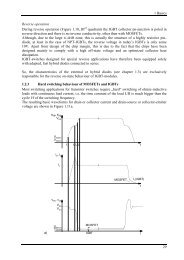
The commutation goes back and forth between T4 and<br />
D6; the current flows from the AC terminal across T3 and<br />
T4 to DC- as long as T4 is switched on. As soon as T4<br />
switches off, the current commutates to the clamping<br />
diode D6; the new conduction path is from AC vie T3 and<br />
D6 to N. T3 stays switched on all the time.<br />
T4<br />
D4<br />
TNPC:<br />
There are no “short” or “long” commutation paths in<br />
TNPC topology; all paths are of the same geometric<br />
length and inherit one outer switch (indices 1 or 4; either<br />
IGBT or diode) and two inner switches (either T2 and D3<br />
or T3 and D2). In normal operation the commutation<br />
always affects one outer and two inner switches; there is<br />
no commutation between T1/D1 and T4/D4 except when<br />
an emergency shut-down happens.<br />
In operating area 1 (Fig. 16 & Fig. 9) output voltage and<br />
current are positive, the current flows towards the AC<br />
terminal. The commutation goes back and forth between<br />
T1 and T2/D3; the current flows from DC+ via T1 to the<br />
© by SEMIKRON<br />
2012-09-03 – Rev04<br />
5 / 12