Application Note - Semikron
Application Note - Semikron
Application Note - Semikron

You also want an ePaper? Increase the reach of your titles
YUMPU automatically turns print PDFs into web optimized ePapers that Google loves.
<strong>Application</strong> <strong>Note</strong> AN-11001<br />
<br />
<br />
<br />
NPC:<br />
<br />
<br />
<br />
TNPC:<br />
<br />
<br />
reduced leading to reduced switching power<br />
losses.<br />
Subsequently operation at a working point<br />
producing the same switching frequency as in<br />
2L topology the current THD can be reduced in<br />
3L topology.<br />
In 3L applications the switching frequency can<br />
be reduced compared to 2L applications, still<br />
improving the THD and reducing the filtering<br />
effort.<br />
As the number of IGBTs has increased from 2 to<br />
4 also the number of gate drivers increases.<br />
The auxiliary power consumption grows as well<br />
as the control effort.<br />
The number of switches in the active current<br />
path in 3L NPC topology is doubled; that<br />
increases the conduction power losses.<br />
In 3L NPC applications semiconductors with a<br />
lower blocking voltage capability may be used;<br />
example: DC-link voltage of 750V can be<br />
handled with 1200V 2L or 650V 3L modules<br />
(each switch only needs to block 375V). The<br />
lower losses of the lower blocking devices<br />
compensate the additional losses due to the<br />
increased number of devices in the current path.<br />
The maximum DC-link voltages are 800V DC<br />
using 650V semiconductors, 1500V DC using<br />
1200V semiconductors and 2400V DC using<br />
1700V semiconductors.<br />
The number of switches in the active current<br />
path in 3L TNPC topology is either similar to 2L<br />
(outer switches) producing the same losses or<br />
doubled (with lower blocking voltage; inner<br />
switches) leading to higher conduction but lower<br />
switching losses.<br />
The maximum DC-link voltages are as for a 2L<br />
module: 400V DC using 650V semiconductors,<br />
800V DC using 1200V semiconductors and<br />
1200V DC using 1700V semiconductors.<br />
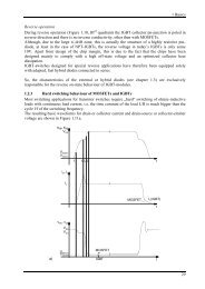
Switching pattern of a 3L converter<br />
The control of 3L applications is more sophisticated than<br />
2L. While the 2L switching pattern is pretty simple (TOP<br />
and BOT IGBTs always switch inversely) it gets more<br />
complicated at 3L as certain switches (namely T2 and<br />
T3) are switched on for quite a while depending on the<br />
value of cos (up to a half period for cos = ). The<br />
number of possible switching states increases from 4 in<br />
2L topology (TOP/BOT: 0/0, 0/1, 1/0, 1/1) to 16.<br />
At 3L NPC a distinction is drawn between allowed,<br />
potentially destructive and destructive states (Fig. 5).<br />
Fig. 5: Switching states NPC<br />
T1 0 0 0 1 0 0 1 0 1 1 0 1 1 1 0 1<br />
T2 0 1 0 1 1 0 0 0 0 0 1 1 1 0 1 1<br />
T3 0 0 1 0 1 1 0 0 0 1 0 1 0 1 1 1<br />
T4 0 0 0 0 0 1 0 1 1 0 1 0 1 1 1 1<br />
state allowed potentially destructive destructive<br />
Allowed states:<br />
<br />
<br />
<br />
All IGBTs are in off-state; the converter is<br />
switched off.<br />
Either T2 or T3 may be switched on solely.<br />
Each state where two adjacent IGBTs are<br />
switched on (T1/T2, T2/T3, T3/T4).<br />
Potentially destructive states:<br />
Either T1 or T4 is switched on solely or together.<br />
Two not adjacent IGBTs are switched on (T1/T3<br />
or T2/T4).<br />
The consequences depend on the switching pattern<br />
applied to the modules of the other phase legs.<br />
Destructive states:<br />
Three adjacent IGBTs are switched on<br />
(T1/T2/T3 → shorting upper half of DC-link;<br />
T2/T3/T4 → shorting lower half of DC-link)<br />
Three not adjacent IGBTs are switched on<br />
(T1/T2/T4 → full DC-link voltage applies to T3;<br />
T1/T3/T4 → full DC-link voltage applies to T2)<br />
Four IGBTs switched on → DC+, DC- and N<br />
shorted.<br />
At 3L TNPC the distinction is drawn only between<br />
allowed and destructive states (Fig. 6).<br />
Fig. 6: Switching states TNPC<br />
T1 0 1 0 0 0 1 0 0 1 0 1 0 1 1 1 1<br />
T2 0 0 1 0 0 1 1 0 0 1 0 1 0 1 1 1<br />
T3 0 0 0 1 0 0 1 1 1 0 0 1 1 0 1 1<br />
T4 0 0 0 0 1 0 0 1 0 1 1 1 1 1 0 1<br />
state allowed destructive<br />
Allowed states:<br />
<br />
<br />
<br />
All IGBTs are in off-state; the converter is<br />
switched off.<br />
Any one of the IGBTs may be switched on<br />
solely.<br />
Each state where two adjacent IGBTs are<br />
switched on (T1/T2, T2/T3 or T3/T4).<br />
Destructive states:<br />
<br />
Two not adjacent IGBTs are switched on<br />
(T1/T3 → shorting upper half of DC-link;<br />
T2/T4 → shorting lower half of DC-link;<br />
T1/T4 → shorting DC+ and DC-).<br />
© by SEMIKRON<br />
2012-09-03 – Rev04<br />
3 / 12