Application Note - Semikron
Application Note - Semikron
Application Note - Semikron

You also want an ePaper? Increase the reach of your titles
YUMPU automatically turns print PDFs into web optimized ePapers that Google loves.
<strong>Application</strong> <strong>Note</strong> AN-11001<br />
Fig. 1: Green box: content of a 3L NPC phase leg<br />
DC+<br />
C1<br />
T1 D1<br />
D5<br />
T2 D2<br />
N<br />
AC<br />
DC-link voltage. The inner switches (indices 2 and 3)<br />
connect AC to Neutral and must be able to block half of<br />
the DC-link voltage.<br />
In 3L TNPC topology the conduction paths are either<br />
through one higher blocking semiconductors (outer<br />
switch) or two lower blocking devices in series (inner<br />
switches).<br />
Naming the semiconductors as shown in Fig. 1 and Fig.<br />
2 inherits the advantage that the exact same switching<br />
pattern can be used for both 3L NPC and 3L TNPC<br />
topology.<br />
D6<br />
T3<br />
D3<br />
Difference 2L 3L<br />
C2<br />
DC-<br />
Four power terminals connect the module to AC and to<br />
the DC-link: DC+, DC- and N (neutral). The DC-link is<br />
split in two symmetric halves connected in series; the<br />
upper half connecting DC+ and N and the lower half<br />
connecting N and DC-.<br />
In this 3L topology every conduction path consists of two<br />
semiconductors in series and it can either handle higher<br />
DC-link voltages or the blocking voltage of the switches<br />
can be reduced in comparison to a 2L topology.<br />
T4<br />
D4<br />
The difference between 2L and 3L topology is not only<br />
the number of semiconductor devices. While the wellknown<br />
2L converter switches either DC+ or DC- to the<br />
AC terminal (Fig. 3), the 3L versions connect the AC<br />
either to DC+, DC- or N. N(eutral) is the midpoint voltage<br />
between DC+ and DC- and forms the third voltage level<br />
where the three level topology has its name from.<br />
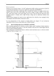
Fig. 3: Voltage and current waveforms of 2L<br />
-VDC/2<br />
VDC/2 -VDC VDC<br />
0<br />
Output voltage (line to line)<br />
Output current<br />
Fig. 2: Green box: content of a 3L TNPC phase leg<br />
Fig. 4: Voltage and current waveforms of 3L<br />
DC+<br />
C1<br />
N<br />
D2<br />
T2<br />
T1<br />
T3<br />
D3<br />
T4<br />
D1<br />
D4<br />
AC<br />
-VDC/2<br />
VDC/2 -VDC VDC<br />
0<br />
Output voltage (line to line)<br />
Output current<br />
C2<br />
The benefit of 3L TNPC is the 3L output voltage<br />
waveform while there are no restrictions to the switching<br />
scheme as in 3L NPC (especially in emergency shutdown).<br />
DC-<br />
A 3L TNPC phase leg (Fig. 2) consists of only 8<br />
semiconductors: 4 IGBTs (T1 - T4) and 4 antiparallel<br />
Free-Wheeling Diodes (FWD; D1 - D4). As a 3L NPC the<br />
TNPC is connected to the split DC-link at DC+, N and<br />
DC-. The fourth power terminal provides the AC output.<br />
In 3L TNPC topology semiconductors with different<br />
breakdown voltages are used: T1 and T4 (which are<br />
refered to as outer switches) need to withstand the full<br />
By introducing a third voltage level the waveform of the<br />
output voltage is approximated closer to the desired sine<br />
waveform (Fig. 4) and the current THD can be reduced.<br />
Thus strong requirements concerning grid quality (when<br />
feeding to the grid) can be met more easily.<br />
Comparison of 2L 3L NPC/TNPC:<br />
NPC & TNPC:<br />
<br />
For reaching the same current THD value with<br />
3L topology the switching frequency can be<br />
2 / 12 2012-09-03 – Rev04 © by SEMIKRON