Application Note - Semikron
Application Note - Semikron
Application Note - Semikron

Create successful ePaper yourself
Turn your PDF publications into a flip-book with our unique Google optimized e-Paper software.
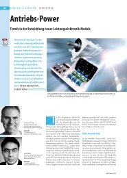
<strong>Application</strong> <strong>Note</strong><br />
AN-11001<br />
Revision:<br />
Issue Date:<br />
Prepared by:<br />
04<br />
2012-09-03<br />
Ingo Staudt<br />
Key Words: 3L, NPC, TNPC, NPC2, MNPC, Multilevel, Loss Calculation,<br />
SemiSel<br />
3L NPC & TNPC Topology<br />
General ................................................................................................................................................................. 1<br />
Difference 2L 3L ............................................................................................................................................... 2<br />
Switching pattern of a 3L converter ...................................................................................................................... 3<br />
Commutations and commutation paths ................................................................................................................ 4<br />
3L converter .......................................................................................................................................................... 6<br />
Module consideration ............................................................................................................................................ 6<br />
Setup with standard 2L modules .......................................................................................................................... 6<br />
Dedicated 3L modules .......................................................................................................................................... 7<br />
SEMIKRON 3L modules ....................................................................................................................................... 7<br />
Driving 3L devices ................................................................................................................................................ 7<br />
Normal operation sequences ................................................................................................................................ 7<br />
Emergency shut-down .......................................................................................................................................... 8<br />
Protection of 3L devices against voltage overshoots ........................................................................................... 8<br />
Snubber ................................................................................................................................................................ 8<br />
Active Clamping .................................................................................................................................................... 8<br />
3L loss calculation ................................................................................................................................................ 9<br />
SemiSel ............................................................................................................................................................... 11<br />
Symbols and Terms used ................................................................................................................................... 11<br />
References.......................................................................................................................................................... 12<br />
This application note provides information on two three level topologies: the three level NPC (3L NPC; Neutral Point<br />
Clamped) and the three level TNPC (3L TNPC; T-type Neutral Point Clamped). The reader will gain insight in elementary<br />
thoughts of how these 3L devices work; where advantages and disadvantages are. Some hints concerning the layout/setup<br />
of 3L modules are given as well. However, the information given is not exhaustive and the responsibility for a proper design<br />
remains with the user.<br />
General<br />
One benefit of using 3L NPC or 3L TNPC topology is the<br />
lower current THD; that reduces the filtering effort (less<br />
copper needed, lower losses in the filter).<br />
A major advantage of 3L NPC is the possibility to use<br />
IGBTs and diodes with breakdown voltages that are<br />
lower than the actual DC-link voltage. The lower blocking<br />
devices produce lower losses and so the efficiency can<br />
be increased. By using the same blocking voltage as in a<br />
2L applications higher DC-link voltages can be realized.<br />
Compared to a 2L phase leg module one phase leg of a<br />
3L NPC module consists of 10 instead of 4<br />
semiconductors (Fig. 1): 4 IGBTs (T1 - T4), 4 antiparallel<br />
Free-Wheeling Diodes (FWD; D1 - D4) and 2 Clamping<br />
Diodes (CD; D5 and D6).<br />
© by SEMIKRON<br />
2012-09-03 – Rev04<br />
1 / 12
<strong>Application</strong> <strong>Note</strong> AN-11001<br />
Fig. 1: Green box: content of a 3L NPC phase leg<br />
DC+<br />
C1<br />
T1 D1<br />
D5<br />
T2 D2<br />
N<br />
AC<br />
DC-link voltage. The inner switches (indices 2 and 3)<br />
connect AC to Neutral and must be able to block half of<br />
the DC-link voltage.<br />
In 3L TNPC topology the conduction paths are either<br />
through one higher blocking semiconductors (outer<br />
switch) or two lower blocking devices in series (inner<br />
switches).<br />
Naming the semiconductors as shown in Fig. 1 and Fig.<br />
2 inherits the advantage that the exact same switching<br />
pattern can be used for both 3L NPC and 3L TNPC<br />
topology.<br />
D6<br />
T3<br />
D3<br />
Difference 2L 3L<br />
C2<br />
DC-<br />
Four power terminals connect the module to AC and to<br />
the DC-link: DC+, DC- and N (neutral). The DC-link is<br />
split in two symmetric halves connected in series; the<br />
upper half connecting DC+ and N and the lower half<br />
connecting N and DC-.<br />
In this 3L topology every conduction path consists of two<br />
semiconductors in series and it can either handle higher<br />
DC-link voltages or the blocking voltage of the switches<br />
can be reduced in comparison to a 2L topology.<br />
T4<br />
D4<br />
The difference between 2L and 3L topology is not only<br />
the number of semiconductor devices. While the wellknown<br />
2L converter switches either DC+ or DC- to the<br />
AC terminal (Fig. 3), the 3L versions connect the AC<br />
either to DC+, DC- or N. N(eutral) is the midpoint voltage<br />
between DC+ and DC- and forms the third voltage level<br />
where the three level topology has its name from.<br />
Fig. 3: Voltage and current waveforms of 2L<br />
-VDC/2<br />
VDC/2 -VDC VDC<br />
0<br />
Output voltage (line to line)<br />
Output current<br />
Fig. 2: Green box: content of a 3L TNPC phase leg<br />
Fig. 4: Voltage and current waveforms of 3L<br />
DC+<br />
C1<br />
N<br />
D2<br />
T2<br />
T1<br />
T3<br />
D3<br />
T4<br />
D1<br />
D4<br />
AC<br />
-VDC/2<br />
VDC/2 -VDC VDC<br />
0<br />
Output voltage (line to line)<br />
Output current<br />
C2<br />
The benefit of 3L TNPC is the 3L output voltage<br />
waveform while there are no restrictions to the switching<br />
scheme as in 3L NPC (especially in emergency shutdown).<br />
DC-<br />
A 3L TNPC phase leg (Fig. 2) consists of only 8<br />
semiconductors: 4 IGBTs (T1 - T4) and 4 antiparallel<br />
Free-Wheeling Diodes (FWD; D1 - D4). As a 3L NPC the<br />
TNPC is connected to the split DC-link at DC+, N and<br />
DC-. The fourth power terminal provides the AC output.<br />
In 3L TNPC topology semiconductors with different<br />
breakdown voltages are used: T1 and T4 (which are<br />
refered to as outer switches) need to withstand the full<br />
By introducing a third voltage level the waveform of the<br />
output voltage is approximated closer to the desired sine<br />
waveform (Fig. 4) and the current THD can be reduced.<br />
Thus strong requirements concerning grid quality (when<br />
feeding to the grid) can be met more easily.<br />
Comparison of 2L 3L NPC/TNPC:<br />
NPC & TNPC:<br />
<br />
For reaching the same current THD value with<br />
3L topology the switching frequency can be<br />
2 / 12 2012-09-03 – Rev04 © by SEMIKRON
<strong>Application</strong> <strong>Note</strong> AN-11001<br />
<br />
<br />
<br />
NPC:<br />
<br />
<br />
<br />
TNPC:<br />
<br />
<br />
reduced leading to reduced switching power<br />
losses.<br />
Subsequently operation at a working point<br />
producing the same switching frequency as in<br />
2L topology the current THD can be reduced in<br />
3L topology.<br />
In 3L applications the switching frequency can<br />
be reduced compared to 2L applications, still<br />
improving the THD and reducing the filtering<br />
effort.<br />
As the number of IGBTs has increased from 2 to<br />
4 also the number of gate drivers increases.<br />
The auxiliary power consumption grows as well<br />
as the control effort.<br />
The number of switches in the active current<br />
path in 3L NPC topology is doubled; that<br />
increases the conduction power losses.<br />
In 3L NPC applications semiconductors with a<br />
lower blocking voltage capability may be used;<br />
example: DC-link voltage of 750V can be<br />
handled with 1200V 2L or 650V 3L modules<br />
(each switch only needs to block 375V). The<br />
lower losses of the lower blocking devices<br />
compensate the additional losses due to the<br />
increased number of devices in the current path.<br />
The maximum DC-link voltages are 800V DC<br />
using 650V semiconductors, 1500V DC using<br />
1200V semiconductors and 2400V DC using<br />
1700V semiconductors.<br />
The number of switches in the active current<br />
path in 3L TNPC topology is either similar to 2L<br />
(outer switches) producing the same losses or<br />
doubled (with lower blocking voltage; inner<br />
switches) leading to higher conduction but lower<br />
switching losses.<br />
The maximum DC-link voltages are as for a 2L<br />
module: 400V DC using 650V semiconductors,<br />
800V DC using 1200V semiconductors and<br />
1200V DC using 1700V semiconductors.<br />
Switching pattern of a 3L converter<br />
The control of 3L applications is more sophisticated than<br />
2L. While the 2L switching pattern is pretty simple (TOP<br />
and BOT IGBTs always switch inversely) it gets more<br />
complicated at 3L as certain switches (namely T2 and<br />
T3) are switched on for quite a while depending on the<br />
value of cos (up to a half period for cos = ). The<br />
number of possible switching states increases from 4 in<br />
2L topology (TOP/BOT: 0/0, 0/1, 1/0, 1/1) to 16.<br />
At 3L NPC a distinction is drawn between allowed,<br />
potentially destructive and destructive states (Fig. 5).<br />
Fig. 5: Switching states NPC<br />
T1 0 0 0 1 0 0 1 0 1 1 0 1 1 1 0 1<br />
T2 0 1 0 1 1 0 0 0 0 0 1 1 1 0 1 1<br />
T3 0 0 1 0 1 1 0 0 0 1 0 1 0 1 1 1<br />
T4 0 0 0 0 0 1 0 1 1 0 1 0 1 1 1 1<br />
state allowed potentially destructive destructive<br />
Allowed states:<br />
<br />
<br />
<br />
All IGBTs are in off-state; the converter is<br />
switched off.<br />
Either T2 or T3 may be switched on solely.<br />
Each state where two adjacent IGBTs are<br />
switched on (T1/T2, T2/T3, T3/T4).<br />
Potentially destructive states:<br />
Either T1 or T4 is switched on solely or together.<br />
Two not adjacent IGBTs are switched on (T1/T3<br />
or T2/T4).<br />
The consequences depend on the switching pattern<br />
applied to the modules of the other phase legs.<br />
Destructive states:<br />
Three adjacent IGBTs are switched on<br />
(T1/T2/T3 → shorting upper half of DC-link;<br />
T2/T3/T4 → shorting lower half of DC-link)<br />
Three not adjacent IGBTs are switched on<br />
(T1/T2/T4 → full DC-link voltage applies to T3;<br />
T1/T3/T4 → full DC-link voltage applies to T2)<br />
Four IGBTs switched on → DC+, DC- and N<br />
shorted.<br />
At 3L TNPC the distinction is drawn only between<br />
allowed and destructive states (Fig. 6).<br />
Fig. 6: Switching states TNPC<br />
T1 0 1 0 0 0 1 0 0 1 0 1 0 1 1 1 1<br />
T2 0 0 1 0 0 1 1 0 0 1 0 1 0 1 1 1<br />
T3 0 0 0 1 0 0 1 1 1 0 0 1 1 0 1 1<br />
T4 0 0 0 0 1 0 0 1 0 1 1 1 1 1 0 1<br />
state allowed destructive<br />
Allowed states:<br />
<br />
<br />
<br />
All IGBTs are in off-state; the converter is<br />
switched off.<br />
Any one of the IGBTs may be switched on<br />
solely.<br />
Each state where two adjacent IGBTs are<br />
switched on (T1/T2, T2/T3 or T3/T4).<br />
Destructive states:<br />
<br />
Two not adjacent IGBTs are switched on<br />
(T1/T3 → shorting upper half of DC-link;<br />
T2/T4 → shorting lower half of DC-link;<br />
T1/T4 → shorting DC+ and DC-).<br />
© by SEMIKRON<br />
2012-09-03 – Rev04<br />
3 / 12
<strong>Application</strong> <strong>Note</strong> AN-11001<br />
<br />
<br />
Three not adjacent IGBTs are switched on<br />
(same consequences as above: shorting either<br />
upper half or lower half or the full DC-link)<br />
Four IGBTs switched on → DC+, DC- and N<br />
shorted.<br />
4. voltage is greater and current is less than 0 (V ><br />
0, I < 0):<br />
2L: T BOT ↔ D TOP<br />
3L NPC: T3/D6 ↔ D1/D2 (long commutation<br />
path)<br />
3L TNPC: T3/D2 ↔ D1<br />
Commutations and commutation paths<br />
NPC & TNPC:<br />
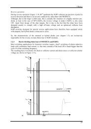
Fig. 7 shows a sine voltage (blue trace) and the related<br />
current (red trace) at inductive load. The inverter<br />
operation can be divided in four operating areas. For cos<br />
= +1 (no phase shift) voltage and current waveforms<br />
are in phase; only working areas 1 and 3 are active. For<br />
cos -1 (180° phase shift) only working areas 2 and<br />
4 are active.<br />
Fig. 7: Operating areas<br />
NPC:<br />
While in a “short commutation path” the commutation<br />
affects only one of the two active switches (e.g. T1 ↔<br />
D5) the current through the other active switch does not<br />
change (e.g. T2). In a “long commutation path” (e.g.<br />
D5/T2 ↔ D3/D4) both devices are affected.<br />
The name “short/long commutation path” also indicates<br />
the geometric length of the commutations; while the short<br />
commutation takes place either within the upper or the<br />
lower half of the 3L module in a long commutation the<br />
current changes from the upper to the lower half (or vice<br />
versa).<br />
0.9<br />
<br />
Fig. 8: Short commutation path in operating area 1<br />
DC+<br />
VDC/2<br />
T1<br />
D1<br />
1.<br />
DC+<br />
VDC/2<br />
T1<br />
D1<br />
Voltage V<br />
Current I<br />
i( t )<br />
u( t )<br />
V > 0<br />
I < 0<br />
V > 0<br />
I > 0<br />
V < 0<br />
I > 0<br />
V < 0<br />
I < 0<br />
V > 0<br />
I < 0<br />
V > 0<br />
I > 0<br />
N<br />
D5<br />
T2<br />
D2<br />
AC<br />
IAC<br />
N<br />
D5<br />
T2<br />
D2<br />
AC<br />
IAC<br />
4 1 2 3<br />
4 1<br />
D6<br />
T3<br />
D3<br />
D6<br />
T3<br />
D3<br />
0.9<br />
0 t<br />
For any value of cos between -1 and +1 the phase shift<br />
changes and so do the time shares of the four working<br />
areas.<br />
The active switches and the commutations for these four<br />
working areas are listed below:<br />
1. both voltage and current are greater than 0 (V ><br />
0, I > 0):<br />
2L: T TOP ↔ D BOT<br />
3L NPC: T1/T2 ↔ D5/T2 (short<br />
commutation path)<br />
3L TNPC: T1 ↔ D3<br />
2. voltage is less and current is greater than 0 (V <<br />
0, I > 0):<br />
2L: T TOP ↔ D BOT<br />
3L NPC: D5/T2 ↔ D3/D4 (long commutation<br />
path)<br />
3L TNPC: T2/D3 ↔ D4<br />
3. both voltage and current are less than 0 (V < 0, I<br />
< 0):<br />
2L: T BOT ↔ D TOP<br />
3L NPC: T3/T4 ↔ T3/D6 (short<br />
commutation path)<br />
3L TNPC: T4 ↔ T3/D2<br />
3<br />
VDC/2<br />
T4<br />
D4<br />
VDC/2<br />
DC-<br />
DC-<br />
The short commutation (Fig. 8) in the upper half of the<br />
module (device indices 1, 2 and 5) is active in operating<br />
area 1 (Fig. 9); both voltage and current are positive.<br />
The commutation goes back and forth between T1 and<br />
D5; the current flows from DC+ via T1 and T2 to the AC<br />
terminal as long as T1 is switched on. When T1 switches<br />
off, the current commutates to the clamping diode D5;<br />
now the current flow is from N via D5 and T2 to AC. T2<br />
stays switched on all the time.<br />
Fig. 9: Operating area 1<br />
<br />
0 .9<br />
Voltage V<br />
Current I<br />
i U( ( tx<br />
))<br />
I ( x )<br />
u ( t )<br />
0 .9<br />
0<br />
V > 0<br />
I < 0<br />
4<br />
V > 0<br />
I > 0<br />
T4<br />
D4<br />
V < 0<br />
I > 0<br />
1 2 3<br />
The long commutation for positive output current (Fig.<br />
10) goes back and forth between D5/T2 in the upper half<br />
of the module and D3/D4 in the lower half => across the<br />
entire device.<br />
4 / 12 2012-09-03 – Rev04 © by SEMIKRON
<strong>Application</strong> <strong>Note</strong> AN-11001<br />
Fig. 10: Long commutation path in operating area 2<br />
Fig. 13: Operating area 3<br />
DC+<br />
VDC/2<br />
N<br />
VDC/2<br />
DC-<br />
D5<br />
D6<br />
T1<br />
T2<br />
T3<br />
T4<br />
D1<br />
D2<br />
AC<br />
D3<br />
D4<br />
IAC<br />
2.<br />
DC+<br />
VDC/2<br />
N<br />
VDC/2<br />
This commutation across the entire device is due to the<br />
fact that in operating area 2 (Fig. 11) the current is still<br />
positive (flowing from the DC-link towards the load) while<br />
the output voltage is negative.<br />
Fig. 11: Operating area 2<br />
<br />
0 .9<br />
i ( t )<br />
u ( t )<br />
0 .9<br />
V > 0<br />
I < 0<br />
D5<br />
D6<br />
T1<br />
T2<br />
T3<br />
T4<br />
D1<br />
D2<br />
AC<br />
D3<br />
D4<br />
IAC<br />
V > 0<br />
I > 0<br />
Voltage V<br />
Current I<br />
V > 0<br />
I < 0<br />
4 1<br />
3<br />
4 1<br />
0 t<br />
0<br />
)<br />
x<br />
V < 0<br />
I < 0<br />
The long commutation path for negative current (Fig. 14)<br />
goes back and forth between D6/T3 in the lower half of<br />
the module and D1/D2 in the upper half across the entire<br />
device.<br />
Fig. 14: Long commutation path in operating area 4<br />
DC+<br />
VDC/2<br />
D5<br />
T1<br />
D1<br />
4.<br />
DC+<br />
VDC/2<br />
D5<br />
T1<br />
D1<br />
V > 0<br />
I > 0<br />
VoltageV<br />
Current I<br />
U<br />
I<br />
1<br />
( x )<br />
( x )<br />
V < 0<br />
I > 0<br />
V < 0<br />
I < 0<br />
V > 0<br />
I < 0<br />
N<br />
V > 0<br />
I > 0<br />
D6<br />
T2<br />
T3<br />
D2<br />
AC<br />
D3<br />
IAC<br />
N<br />
D6<br />
T2<br />
T3<br />
D2<br />
AC<br />
D3<br />
IAC<br />
<br />
1<br />
0<br />
2 3<br />
4 1<br />
VDC/2<br />
T4<br />
D4<br />
VDC/2<br />
DC-<br />
DC-<br />
T4<br />
D4<br />
t<br />
3 <br />
The other short commutation path is active in operating<br />
area 3 (Fig. 12 & Fig. 13), in the lower half of the module.<br />
Output current and voltage are negative.<br />
Fig. 12: Short commutation path in operating area 3<br />
The long commutation in operating area 4 (Fig. 4) comes<br />
with negative output current (flowing from the AC<br />
terminal towards the DC-link) and positive voltage.<br />
Fig. 15: Operating area 4<br />
DC+<br />
VDC/2<br />
N<br />
D5<br />
T1<br />
T2<br />
T3<br />
D1<br />
D2<br />
AC<br />
D3<br />
IAC<br />
3.<br />
DC+<br />
VDC/2<br />
N<br />
D5<br />
T1<br />
T2<br />
T3<br />
D1<br />
D2<br />
AC<br />
D3<br />
IAC<br />
<br />
0 .9<br />
Voltage V<br />
Current I<br />
1<br />
i ( t )<br />
u ( t )<br />
0 .9<br />
V > 0<br />
I < 0<br />
4<br />
V > 0<br />
I > 0<br />
V < 0<br />
I > 0<br />
1 2 3<br />
x<br />
D6<br />
D6<br />
0 <br />
VDC/2<br />
DC-<br />
DC-<br />
T4<br />
D4<br />
VDC/2<br />
DC-<br />
The commutation goes back and forth between T4 and<br />
D6; the current flows from the AC terminal across T3 and<br />
T4 to DC- as long as T4 is switched on. As soon as T4<br />
switches off, the current commutates to the clamping<br />
diode D6; the new conduction path is from AC vie T3 and<br />
D6 to N. T3 stays switched on all the time.<br />
T4<br />
D4<br />
TNPC:<br />
There are no “short” or “long” commutation paths in<br />
TNPC topology; all paths are of the same geometric<br />
length and inherit one outer switch (indices 1 or 4; either<br />
IGBT or diode) and two inner switches (either T2 and D3<br />
or T3 and D2). In normal operation the commutation<br />
always affects one outer and two inner switches; there is<br />
no commutation between T1/D1 and T4/D4 except when<br />
an emergency shut-down happens.<br />
In operating area 1 (Fig. 16 & Fig. 9) output voltage and<br />
current are positive, the current flows towards the AC<br />
terminal. The commutation goes back and forth between<br />
T1 and T2/D3; the current flows from DC+ via T1 to the<br />
© by SEMIKRON<br />
2012-09-03 – Rev04<br />
5 / 12
<strong>Application</strong> <strong>Note</strong> AN-11001<br />
AC terminal as long as T1 is switched on. When T1<br />
switches off, the current commutates to the inner<br />
switches T2/D3; the current now flows from N via T2 and<br />
D3 to AC. T2 stays switched on all the time; as soon as<br />
T1 is switched on, the diode D3 blocks the voltage and<br />
so avoids a short cut of the upper half of the DC-link.<br />
In operating area 4 (Fig. 19) the output current is<br />
negative while the voltage is positive (Fig. 15). The<br />
current commutates back and forth between the inner<br />
switches T3/D2 and the diode D1.<br />
Fig. 19: Commutation path in operating area 4<br />
Fig. 16: Commutation path in operating area 1<br />
DC+<br />
4.<br />
DC+<br />
DC+<br />
VDC/2 VDC/2<br />
N<br />
D2<br />
T2<br />
T3<br />
D3<br />
T1<br />
T4<br />
AC<br />
1.<br />
D1<br />
IAC<br />
D4<br />
DC+<br />
VDC/2 VDC/2<br />
N<br />
D2<br />
T2<br />
T3<br />
D3<br />
T1<br />
T4<br />
AC<br />
D1<br />
IAC<br />
D4<br />
VDC/2 VDC/2<br />
N<br />
DC-<br />
D2<br />
T2<br />
T3<br />
D3<br />
T1<br />
T4<br />
AC<br />
D1<br />
IAC<br />
D4<br />
VDC/2 VDC/2<br />
N<br />
DC-<br />
D2<br />
T2<br />
T3<br />
D3<br />
T1<br />
T4<br />
AC<br />
D1<br />
IAC<br />
D4<br />
DC-<br />
DC-<br />
In operating area 2 (Fig. 17) the output current is still<br />
positive while the voltage is negative (Fig. 11). It<br />
commutates back and forth between the inner switches<br />
T2/D3 and the diode D4.<br />
Fig. 17: Commutation path in operating area 2<br />
DC+<br />
VDC/2 VDC/2<br />
N<br />
DC-<br />
D2<br />
T2<br />
T3<br />
D3<br />
T1<br />
T4<br />
AC<br />
D1<br />
IAC<br />
D4<br />
2.<br />
Fig. 18 shows the conduction paths of operating area 3;<br />
the current commutates between T4 and the inner<br />
switches T3/D2. The current flows from the AC terminal<br />
to the DC-link and, current and voltage are negative (see<br />
Fig. 13). T3 stays switched on permanently; as long as<br />
T4 is switched on as well the diode D2 blocks the voltage<br />
and avoids shorting the negative half of the DC-link.<br />
DC+<br />
VDC/2 VDC/2<br />
N<br />
D2<br />
T2<br />
T3<br />
D3<br />
T1<br />
T4<br />
AC<br />
D1<br />
IAC<br />
D4<br />
3L converter<br />
Module consideration<br />
When a 3L module is designed especially the<br />
commutation paths find consideration: large commutation<br />
paths inherit large stray inductances. When the load<br />
current through a conduction path with large stray<br />
inductance is switched off high voltage overshoots occur.<br />
To avoid a destruction of the semiconductor the voltage<br />
overshoot must stay below its blocking voltage. That can<br />
be reached by either reducing the maximum allowed DClink<br />
voltage and allowing higher overshoots or by<br />
reducing the stray inductances producing less<br />
overshoots.<br />
Of course the aim is to reduce the stray inductance and<br />
allow higher DC-link voltages (that increases the possible<br />
AC output voltage and so the module power).<br />
Setup with standard 2L modules<br />
Theoretically 3L topologies can be set up with already<br />
existing standard 2L modules (Fig. 20 & Fig. 21). The<br />
assembly would require bus bar interconnection of the<br />
modules and would be very scalable.<br />
Fig. 18: Commutation path in operating area 3<br />
DC+<br />
VDC/2 VDC/2<br />
N<br />
D2 T3<br />
3.<br />
D1<br />
T1<br />
AC<br />
IAC<br />
T2 D3<br />
D4<br />
T4<br />
DC+<br />
VDC/2 VDC/2<br />
DC-<br />
DC-<br />
DC-<br />
N<br />
T1<br />
D2 T3<br />
T2 D3<br />
T4<br />
AC<br />
D1<br />
IAC<br />
D4<br />
NPC:<br />
Practically the NPC setup from 2L modules (Fig. 20)<br />
inherits always very long conduction paths, especially for<br />
the commutations across module borders (that gets even<br />
worse for the long commutation paths).<br />
Due to the stray inductance these large commutation<br />
paths produce very high voltage overshoots so that the<br />
shown setups offer no advantages in regard to 2L<br />
designs.<br />
6 / 12 2012-09-03 – Rev04 © by SEMIKRON
<strong>Application</strong> <strong>Note</strong> AN-11001<br />
Fig. 20: 2L configurations to set up a 3L NPC module<br />
T1 D1<br />
T1 D1<br />
GAR<br />
T1<br />
D5 T2 D2<br />
GB<br />
D5 T2 D2 D5<br />
GA<br />
T2<br />
GB<br />
D6<br />
GB<br />
T3 D3 D6 T3 D3 D6<br />
GA<br />
T3<br />
GAL<br />
T4 D4<br />
T4 D4<br />
T4<br />
GB<br />
D1<br />
GA<br />
D2<br />
GA<br />
D3<br />
GA<br />
D4<br />
GA<br />
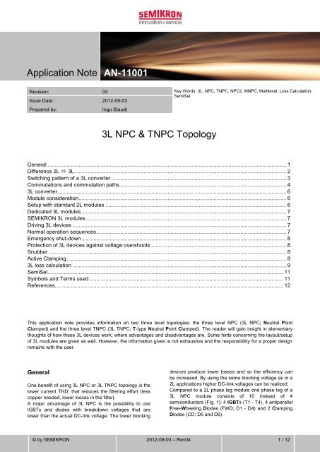
SEMIKRON 3L modules<br />
SEMIKRON provides a number of 3L modules that have<br />
been specially redesigned to minimize stray inductance.<br />
The module range starts with SEMITOP at a rated chip<br />
current of 20A to 150A followed by MiniSKiiP (75A -<br />
200A) up to SKiM modules with 200A - 600A rated<br />
current. While SEMITOP and MiniSKiiP are available for<br />
DC-link voltages of up to approx. 800V, SKiM modules<br />
allow for up to 1500V. The output power range goes as<br />
far as 250kVA (Fig. 22).<br />
As soon as even higher power is required several<br />
modules need to be connected in parallel.<br />
Fig. 22: SEMIKRON 3L module portfolio<br />
SEMITOP 3 & 4<br />
In the TNPC setup from 2L modules (Fig. 21) every<br />
commutation path is across module borders. Similar to<br />
the NPC setup stray inductances lead to high voltage<br />
overshoots which make this solution unattractive.<br />
TNPC:<br />
20 A – 150A<br />
MiniSKiiP 2 & 3<br />
75A – 200A<br />
Fig. 21: 2L configurations to set up a 3L TNPC module<br />
SKiM 4<br />
T1<br />
D1<br />
T1<br />
D1<br />
200A – 600A<br />
D2<br />
T3<br />
D2<br />
T3<br />
GA<br />
5 25 60 80 250 [kVA]<br />
GM<br />
T2<br />
D3<br />
T4<br />
D4<br />
GB<br />
GA<br />
T2<br />
GA<br />
D3<br />
T4<br />
D4<br />
GA<br />
The major benefit of the 1200V NPC module is that a<br />
maximum AC output voltage of 1000V can be realised at<br />
1500V DC-link. So it is possible to stay right within the<br />
low voltage directive (harmonised standards apply) on<br />
the one hand and reduce the converter current on the<br />
other without a change to the output power.<br />
Dedicated 3L modules<br />
As the 3L topology setup from 2L modules appears not to<br />
be the best solution a new module design has been<br />
made facing the special requirements coming with the 3L<br />
technology.<br />
At the very beginning a choice must be made concerning<br />
the module size and the related electric module power:<br />
the bigger the module shall become the more power it<br />
can provide as large chip area is available. Unfortunately<br />
larger module size also stands for higher stray<br />
inductances leading to high switching voltage overshoots<br />
thus limiting the maximum current.<br />
High power can either be realized by one large module or<br />
by many smaller modules in parallel. The latter solution<br />
requires an equally high number of driving units that<br />
need to be parallelized (with known problems: cost,<br />
space, jitter of separate drivers, compensation current<br />
when using paralleled drivers…).<br />
Driving 3L devices<br />
Normal operation sequences<br />
NPC:<br />
When all devices are switched off and the NPC converter<br />
starts operation it must be one of the inner IGBTs to be<br />
switched on first. In case of positive output voltage that is<br />
T2. After a short while (when T2 is entirely switched on)<br />
T1 may be pulsed. For the switch-off sequence the<br />
reverse order must be maintained: it must be made sure<br />
that T1 is thoroughly switched off before T2 may be<br />
turned off. That can be achieved by turning off T2 a short<br />
time (1..3µs) after the turn-off signal for T1 has occurred;<br />
this dead time is well known as interlock-time between<br />
TOP and BOT switch at SEMIKRON 2L gate drivers.<br />
© by SEMIKRON<br />
2012-09-03 – Rev04<br />
7 / 12
<strong>Application</strong> <strong>Note</strong> AN-11001<br />
When an inner IGBT (T2 or T3) is switched off before the<br />
corresponding outer IGBT (T1 or T4) the inner switch<br />
would be exposed to the full DC-link voltage. In case this<br />
voltage was higher than the blocking voltage of that<br />
semiconductor it would be destroyed.<br />
As shown in Fig. 4 there are switching patterns that are<br />
not allowed because they are destructive. Those states<br />
must be avoided if the device shall not be destroyed.<br />
TNPC:<br />
There is no mandatory switching sequence for the TNPC<br />
converter: any IGBT may be switched on and off at any<br />
time because there is no danger that one semiconductor<br />
is exposed to a voltage higher than its blocking voltage.<br />
NPC & TNPC:<br />
The gate signals of T1 and T3 (T2 and T4 respectively)<br />
are invers. It has to be made sure that one IGBT is<br />
securely switched off before the other one is switched on.<br />
Emergency shut-down<br />
There are several events that may occur which in 2L<br />
application lead to immediate switch-off by the driver to<br />
protect the semiconductors. Imaginable events are:<br />
- thermal overload<br />
- current overload or<br />
- desaturation.<br />
Any of these scenarios must lead to a quick shut-down in<br />
3L application as well.<br />
NPC:<br />
But it must be made sure that the correct switch-off<br />
sequence is maintained: outer IGBT first (T1 or T4), inner<br />
IGBT afterwards (T2 or T3) to avoid destruction due to<br />
voltage breakdown.<br />
Where thermal overload or a slowly rising current can be<br />
monitored with NTC/PTC and current sensors and leave<br />
some time for the supervising controller to react in an<br />
appropriate time, a desaturation event leaves a<br />
maximum of 10µs time for switch-off.<br />
When an outer switch (T1 or T4) desaturates it may be<br />
switched off immediately by the driver. After 1..3µs the<br />
according inner IGBT is to be switched off as well.<br />
It gets more complicated, when the desaturation happens<br />
at an inner switch (T2 or T3): when the event is<br />
monitored the driver must have the information if an<br />
according outer switch is switched on as well or not. If it<br />
is switched on the gate driver must switch off the outer<br />
IGBT immediately, wait 1..3µs and then switch off the<br />
inner IGBT as well. If no outer IGBT is switched on the<br />
driver must switch off the inner IGBT immediately.<br />
In any case the driver generates an error message so<br />
that the controller can shut down the other devices of the<br />
converter as well and so establish a secure state.<br />
TNPC:<br />
Again it is much easier in TNPC topology because no<br />
switch-off sequence must be maintained.<br />
No matter if thermal or current overload or a desaturation<br />
event happens, the converter may be switched off<br />
immediately.<br />
Protection of 3L devices against voltage<br />
overshoots<br />
As soon as a current path is interrupted (by switching off<br />
an IGBT or a diode) the voltage across the switched off<br />
device begins to rise. This voltage overshoot is caused<br />
by the energy stored as magnetic field of the current<br />
path. The energy increases linearly with rising stray<br />
inductance L S (E = 0.5*L S*i²); e.g. doubled parasitic<br />
inductance L S causes doubled energy E. The voltage<br />
overshoot (V = L S*di/dt) is added to the DC-link voltage;<br />
the sum must not exceed the blocking voltage of the<br />
semiconductor as it would be destroyed.<br />
Due to the fact that a 3L module is larger than a 2L<br />
device and a conduction path inherits two switches the<br />
current paths are longer and hence the stray inductances<br />
higher. Especially the long commutation paths (NPC<br />
topology; T2/D5 D3/D4 or T3/D6 D1/D2) must be<br />
payed attention to when the module is designed.<br />
While with a good design low values of the stray<br />
inductances can be realised (e.g. SKiM4 MLI: 28nH per<br />
switch, approx. 60nH for the long commutation path) it is<br />
not possible to construct a low inductive 3L setup with<br />
standard 2L modules. The long commutation path<br />
passes at least three modules in NPC topology (see Fig.<br />
20) or two ot three modules in TNPC topology (Fig. 21)<br />
what leads to a stray inductance of about 200nH. That is<br />
more than three times as much as in the dedicated 3L<br />
module. Assuming the di/dt is the same this setup<br />
produces more than three times as much voltage<br />
overshoot.<br />
For that reason SEMIKRON recommends the use of<br />
dedicated 3L modules.<br />
If there are no further possibilities to reduce the voltage<br />
overshoot at its root cause (i.e. even shorter connections<br />
between the semiconductors which at a certain point is<br />
not possible any more) the overshoot needs to be<br />
handled in a way protecting the semiconductors.<br />
Snubber<br />
Snubber capacitors can be connected to DC+ and N<br />
respectively N and DC-. They must be positioned as<br />
close to the module as possible and can be chosen<br />
according to the hints given in SEMIKRON <strong>Application</strong><br />
<strong>Note</strong> AN-7006.<br />
Active Clamping<br />
Another way to handle harmful voltages is to use an<br />
active clamping network at the IGBTs (Fig. 23).<br />
8 / 12 2012-09-03 – Rev04 © by SEMIKRON
<strong>Application</strong> <strong>Note</strong> AN-11001<br />
This network consists of several in series connected<br />
transient voltage suppressor (TVS) diodes providing a<br />
breakdown voltage which is slightly below the IGBT’s<br />
breakdown voltage. The clamping network is connected<br />
between collector and gate of the device that shall be<br />
protected.<br />
When the switch is turned off and the voltage across<br />
increases above the breakdown voltage of the TVS<br />
diodes they start conducting a current into the gate of the<br />
IGBT. The IGBT starts conducting as well; that leads to a<br />
voltage breakdown across the device as soon as the<br />
energy stored as magnetic field is exhausted, the TVS<br />
diodes go into blocking mode again and the IGBT<br />
switches off.<br />
Fig. 23: Simple active clamping circuit<br />
Gate<br />
driver<br />
TVS<br />
3L loss calculation<br />
For choosing a 3L module that is best suited for a certain application it is necessary to calculate the power losses that<br />
emerge in the different semiconductors. Subsequently the equations for calculating the power losses in 3L NPC and 3L<br />
TNPC are shown.<br />
NPC:<br />
The power losses of the 10 semiconductors in 3L NPC topology can be calculated according to:<br />
T1 & T4:<br />
P<br />
P<br />
cond<br />
MIˆ<br />
<br />
12<br />
<br />
3V<br />
<br />
cos(<br />
)<br />
sin( )<br />
<br />
2r<br />
Iˆ<br />
1<br />
cos( <br />
ce0 <br />
ce )<br />
<br />
<br />
Iˆ<br />
<br />
<br />
<br />
K I<br />
<br />
<br />
V<br />
<br />
KV<br />
1<br />
cos( GI<br />
CC<br />
sw<br />
f<br />
sw<br />
Esw<br />
<br />
)<br />
I <br />
ref<br />
V <br />
ref 2<br />
<br />
<br />
<br />
<br />
1<br />
<br />
<br />
2<br />
<br />
T2 & T3:<br />
P<br />
P<br />
cond<br />
<br />
Iˆ<br />
V<br />
12<br />
12<br />
3M<br />
<br />
cos( )<br />
sin( )<br />
<br />
r Iˆ<br />
3<br />
2M<br />
1<br />
cos( <br />
2<br />
ce0 <br />
ce<br />
)<br />
<br />
<br />
Iˆ<br />
<br />
<br />
<br />
K I<br />
<br />
<br />
V<br />
<br />
KV<br />
1<br />
cos( GI<br />
CC<br />
sw<br />
f<br />
sw<br />
Esw<br />
<br />
)<br />
I <br />
ref<br />
V <br />
ref 2<br />
<br />
<br />
<br />
<br />
1<br />
<br />
<br />
<br />
<br />
D5 & D6:<br />
P<br />
P<br />
cond<br />
<br />
Iˆ<br />
V<br />
12<br />
<br />
<br />
ˆ<br />
2<br />
12<br />
3M<br />
2<br />
<br />
cos( )<br />
2sin( )<br />
r I 3<br />
4M<br />
1<br />
cos ( ) <br />
f 0 <br />
f<br />
<br />
<br />
<br />
Iˆ<br />
<br />
<br />
<br />
K I<br />
<br />
<br />
V<br />
<br />
KV<br />
1<br />
cos( GI<br />
CC<br />
sw<br />
f<br />
sw<br />
Esw<br />
<br />
)<br />
I <br />
ref<br />
V <br />
ref 2<br />
<br />
<br />
<br />
<br />
1<br />
<br />
<br />
<br />
<br />
© by SEMIKRON<br />
2012-09-03 – Rev04<br />
9 / 12
<strong>Application</strong> <strong>Note</strong> AN-11001<br />
D1 & D4:<br />
P<br />
P<br />
cond<br />
MIˆ<br />
<br />
12<br />
<br />
3V<br />
<br />
cos( )<br />
sin( )<br />
<br />
2r<br />
Iˆ<br />
1<br />
cos( <br />
f 0 <br />
f )<br />
K I<br />
<br />
<br />
Iˆ<br />
<br />
<br />
<br />
<br />
<br />
V<br />
<br />
KV<br />
1<br />
cos( GI<br />
CC<br />
sw<br />
f<br />
sw<br />
Esw<br />
<br />
)<br />
I <br />
ref<br />
V <br />
ref 2<br />
<br />
<br />
<br />
<br />
1<br />
<br />
<br />
2<br />
<br />
D2 & D3:<br />
P<br />
cond<br />
P sw<br />
MIˆ<br />
<br />
12<br />
0<br />
<br />
3V<br />
<br />
cos( )<br />
sin( )<br />
<br />
2r<br />
Iˆ<br />
1<br />
cos( <br />
f 0<br />
<br />
f<br />
)<br />
2<br />
<br />
TNPC:<br />
The power losses of the eight semiconductors in 3L TNPC topology are different from those of 3L NPC and can be<br />
calculated as follows:<br />
T1 & T4:<br />
P<br />
P<br />
cond<br />
MIˆ<br />
<br />
12<br />
<br />
3V<br />
<br />
cos(<br />
)<br />
sin( )<br />
<br />
2r<br />
Iˆ<br />
1<br />
cos( <br />
ce0 <br />
ce )<br />
K I<br />
<br />
<br />
Iˆ<br />
<br />
<br />
<br />
<br />
<br />
V<br />
<br />
KV<br />
1<br />
cos( GI<br />
CC<br />
sw<br />
f<br />
sw<br />
Esw<br />
<br />
)<br />
I <br />
ref<br />
V <br />
ref 2<br />
<br />
<br />
<br />
<br />
1<br />
<br />
<br />
2<br />
<br />
T2 & T3:<br />
P<br />
P<br />
cond<br />
<br />
Iˆ<br />
V<br />
12<br />
<br />
<br />
ˆ<br />
2<br />
12<br />
6M<br />
cos( )<br />
sin( )<br />
3M<br />
cos( )<br />
r I 3<br />
4M<br />
1<br />
cos ( ) <br />
ce0 <br />
ce<br />
<br />
K I<br />
<br />
<br />
Iˆ<br />
<br />
<br />
<br />
<br />
<br />
V<br />
<br />
KV<br />
1<br />
cos( GI<br />
CC<br />
sw<br />
f<br />
sw<br />
Esw<br />
<br />
)<br />
I <br />
ref<br />
V <br />
ref 2<br />
<br />
<br />
<br />
<br />
1<br />
<br />
<br />
<br />
<br />
D2 & D3:<br />
P<br />
P<br />
cond<br />
<br />
Iˆ<br />
V<br />
12<br />
<br />
<br />
ˆ<br />
2<br />
12<br />
3M<br />
2<br />
cos( )<br />
2sin( )<br />
3M<br />
cos( )<br />
r I 3<br />
4M<br />
1<br />
cos ( ) <br />
f 0 <br />
ce<br />
<br />
K I<br />
<br />
<br />
Iˆ<br />
<br />
<br />
<br />
<br />
<br />
V<br />
<br />
KV<br />
1<br />
cos( GI<br />
CC<br />
sw<br />
f<br />
sw<br />
Esw<br />
<br />
)<br />
I <br />
ref<br />
V <br />
ref 2<br />
<br />
<br />
<br />
<br />
1<br />
<br />
<br />
<br />
<br />
D1 & D4:<br />
P<br />
P<br />
cond<br />
MIˆ<br />
<br />
12<br />
<br />
3V<br />
<br />
cos( )<br />
sin( )<br />
<br />
2r<br />
Iˆ<br />
1<br />
cos( <br />
f 0 <br />
f )<br />
K I<br />
<br />
<br />
Iˆ<br />
<br />
<br />
<br />
<br />
<br />
V<br />
<br />
KV<br />
1<br />
cos( GI<br />
CC<br />
sw<br />
f<br />
sw<br />
Esw<br />
<br />
)<br />
I <br />
ref<br />
V <br />
ref 2<br />
<br />
<br />
<br />
<br />
1<br />
<br />
<br />
2<br />
<br />
10 / 12 2012-09-03 – Rev04 © by SEMIKRON
<strong>Application</strong> <strong>Note</strong> AN-11001<br />
NPC & TNPC:<br />
The equations are valid for M = 0…1. The modulation<br />
index M correlates DC-link voltage and RMS voltage:<br />
M <br />
2 V<br />
V<br />
3 <br />
RMS<br />
DC<br />
2<br />
Typical values of K V, K I and G I for SEMIKRON modules<br />
are shown in Fig. 16.<br />
Fig. 16: Typ. K V, K I and G I values for SEMIKRON modules<br />
IGBT<br />
Diode<br />
K V 1.4 0.6<br />
K I<br />
1 0.6<br />
G I 1 1.15<br />
SemiSel<br />
SemiSel is SEMIKRON’s online simulation tool to<br />
calculate losses and temperatures of power<br />
semiconductors in customer specific applications.<br />
From specific values for cooling (e.g. type and<br />
performance of the heatsink, ambient temperature) and<br />
electric parameters (e.g. input/output voltage, switching<br />
frequency, load current, etc.) SemiSel calculates the<br />
power losses and junction temperatures of all IGBTs and<br />
diodes within a few seconds. By changing certain<br />
parameters the optimum setup (which type of module,<br />
switching frequency,…) can easily be found.<br />
SemiSel 4.0 has been extended to calculate the 3L NPC<br />
topology in the same convenient way as 2L designs.<br />
Symbols and Terms used<br />
Letter Symbol Term<br />
2L<br />
Two level<br />
3L<br />
Three level<br />
CD<br />
Clamping Diode<br />
cos <br />
Power factor<br />
CS1 Collector Sense of IGBT 1<br />
DC+<br />
Positive potential (terminal) of a direct voltage source<br />
DC-<br />
Negative potential (terminal) of a direct voltage source<br />
di/dt<br />
Rate of rise and fall of current<br />
E<br />
Electrical energy<br />
E SW<br />
f SW<br />
FWD<br />
GA<br />
GAL<br />
GAR<br />
GB<br />
G I<br />
GM<br />
i<br />
Î<br />
I C,NOM<br />
IGBT<br />
I peak<br />
I ref<br />
I RMS<br />
<br />
K I<br />
K V<br />
L S<br />
M<br />
N<br />
NPC<br />
NTC<br />
Sum of energy dissipation during turn-on and turn-off-time<br />
Switching frequency<br />
Free Wheeling Diode<br />
Single Switch<br />
Chopper, low IGBT<br />
Chopper, high IGBT<br />
Half-bridge<br />
Adaptation factor for the non-linear semiconductor characteristics<br />
Half-bridge with anti-serial switches (IGBT and antiparallel diode)<br />
Time dependant value of current<br />
Peak value of current<br />
Nominal collector current<br />
Insulated Gate Bipolar Transistor<br />
Peak value of current<br />
Reference current value of the switching loss measurement<br />
AC terminal current<br />
Conduction angle<br />
Exponent for the current dependency of switching losses<br />
Exponent for the voltage dependency of switching losses<br />
Parasitic inductance / stray inductance<br />
Modulation index<br />
Neutral potential (terminal) of a direct voltage source; midpoint between DC+ and DC-<br />
Neutral Point Clamped<br />
Temperature sensor with negative temperature coefficient<br />
© by SEMIKRON<br />
2012-09-03 – Rev04<br />
11 / 12
<strong>Application</strong> <strong>Note</strong> AN-11001<br />
P<br />
P cond<br />
P SW<br />
PTC<br />
Q<br />
r CE<br />
r f<br />
RMS<br />
R th<br />
S<br />
t<br />
THD<br />
T j<br />
TNPC<br />
TVS<br />
V<br />
V CC<br />
V CE<br />
V ce0<br />
V f0<br />
V CEsat<br />
V DC<br />
V ref<br />
V RMS<br />
Active power<br />
Conduction power losses<br />
Switching power losses<br />
Temperature sensor with positive temperature coefficient<br />
Reactive power<br />
On-state slope resistance (IGBT)<br />
On-state slope resistance (diode)<br />
Root Mean Square<br />
Thermal resistance<br />
Apparent power<br />
Time<br />
Total Harmonic Distortion<br />
Junction temperature<br />
T-type Neutral Point Clamped<br />
Transient voltage suppressor diode<br />
Voltage<br />
Collector-emitter supply voltage<br />
Collector-emitter voltage<br />
Forward threshold voltage (IGBT)<br />
Collector-emitter threshold voltage (diode)<br />
Collector-emitter saturation voltage<br />
Total supply voltage (DC+ to DC-)<br />
Reference voltage value of the switching loss measurement<br />
AC terminal voltage<br />
References<br />
[1] www.SEMIKRON.com<br />
[2] A. Wintrich, U. Nicolai, W. Tursky, T. Reimann,<br />
“<strong>Application</strong> Manual Power Semiconductors”, ISLE<br />
Verlag 2011, ISBN 978-3-938843-666<br />
[3] J. Lamp, "IGBT Peak Voltage Measurement and<br />
Snubber Capacitor Specification", <strong>Application</strong> <strong>Note</strong><br />
AN-7006, SEMIKRON<br />
[4] I. Staudt et al, “Numerical loss calculation and<br />
simulation tool for 3L NPC converter design”, PCIM<br />
Nuremberg, 2011<br />
[5] M. Sprenger et al, „Characterization of a new 1.2kV<br />
IGBT 3L-NPC phase-leg module for low voltage<br />
applications“, EPE 2011<br />
DISCLAIMER<br />
SEMIKRON reserves the right to make changes without further notice herein to improve reliability, function or design.<br />
Information furnished in this document is believed to be accurate and reliable. However, no representation or warranty is<br />
given and no liability is assumed with respect to the accuracy or use of such information. SEMIKRON does not assume any<br />
liability arising out of the application or use of any product or circuit described herein. Furthermore, this technical information<br />
may not be considered as an assurance of component characteristics. No warranty or guarantee expressed or implied is<br />
made regarding delivery, performance or suitability. This document supersedes and replaces all information previously<br />
supplied and may be superseded by updates without further notice.<br />
SEMIKRON products are not authorized for use in life support appliances and systems without the express written approval<br />
by SEMIKRON.<br />
SEMIKRON INTERNATIONAL GmbH<br />
P.O. Box 820251 • 90253 Nürnberg • Deutschland • Tel: +49 911-65 59-234 • Fax: +49 911-65 59-262<br />
sales.skd@semikron.com • www.semikron.com<br />
12 / 12 2012-09-03 – Rev04 © by SEMIKRON