SEMIKRON leading manufacturer of igbt, diode thyristor power ...
SEMIKRON leading manufacturer of igbt, diode thyristor power ...
SEMIKRON leading manufacturer of igbt, diode thyristor power ...

You also want an ePaper? Increase the reach of your titles
YUMPU automatically turns print PDFs into web optimized ePapers that Google loves.
p30-32 Feature Semikron 3/16/06 14:10 Page 30<br />
30 IGBT DRIVERS www.semikron.com<br />
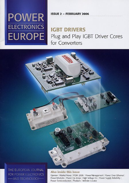
Plug and Play IGBT Driver Cores<br />
for Converters<br />
The key component <strong>of</strong> every <strong>power</strong> electronic system is – besides the <strong>power</strong> modules themselves – the<br />
IGBT driver which forms the vital interface between the <strong>power</strong> transistor and the controller. For this reason,<br />
the choice <strong>of</strong> driver is closely linked with the degree <strong>of</strong> reliability <strong>of</strong> a converter solution. At the same time,<br />
the driver should guarantee maximum system flexibility and user-friendliness. Markus Hermwille,<br />
Product Manager Electronics, <strong>SEMIKRON</strong> Elektronik, Nuremberg, Germany<br />
FRANCAIS<br />
Outre les modules de puissance, le composant clé de tout<br />
système électronique de puissance est l’entraînement à transistor<br />
de puissance à porte isolée qui constitue l’interface essentielle<br />
entre le transistor de puissance et le contrôleur. Pour cette raison,<br />
le choix d’un entraînement est étroitement lié au degré de fiabilité<br />
de la solution de convertisseur. Simultanément, l’entraînement doit<br />
garantir une flexibilité système et une convivialité maximales.<br />
Markus Hermwille, Product Manager Electronics,<br />
<strong>SEMIKRON</strong> Elektronik, Nuremberg, Allemagne<br />
DEUTSCH<br />
Die Schlüsselkomponente jedes leistungselektronischen Systems<br />
ist – neben den Leistungsmodulen selber – der IGBT-Treiber als<br />
vitale Schnittstelle zwischen dem Leistungstransistor und dem<br />
Controller. Aus diesem Grund ist die Auswahl des Treibers eng<br />
verbunden mit dem Grad der Zuverlässigkeit einer<br />
Umrichterlösung. Gleichzeitig sollte der Treiber eine maximale<br />
Systemflexibilität und Anwenderfreundlichkeit garantieren.<br />
Markus Hermwille, Product Manager Electronics,<br />
<strong>SEMIKRON</strong> Elektronik, Nürnberg, Deutschland<br />
In a <strong>power</strong> electronics converter a<br />
microcontroller, for example, provides the<br />
digital control signals needed to control<br />
the overall behaviour. The function <strong>of</strong> the<br />
IGBT driver (Figure 1) is to convert the<br />
incoming digital signals into signals with<br />
sufficient <strong>power</strong> to ensure safe switching<br />
<strong>of</strong> the IGBTs. On the other hand, the<br />
IGBT driver has to provide electrical<br />
isolation between the voltage potentials <strong>of</strong><br />
the microcontroller and the <strong>power</strong><br />
transistors. The use <strong>of</strong> protection elements<br />
is also recommended in order to ensure<br />
that <strong>power</strong> modules are properly and<br />
efficiently protected in the event <strong>of</strong> system<br />
faults.<br />
Thus, drivers used in IGBT <strong>power</strong><br />
modules have to fulfil both gate-drive and<br />
protection functions. They must also<br />
provide potential isolation between the<br />
control system and the <strong>power</strong><br />
semiconductor and be suitable for use in<br />
many different IGBT configurations. To fully<br />
meet these demands, optimised gate-drive<br />
electronics is required. This means finding<br />
the optimum balance between factors such<br />
as functionality, flexibility and costefficiency,<br />
a balance which has been<br />
achieved in the new driver core concept<br />
SKYPER.<br />
Figure 2 shows the block diagram <strong>of</strong> the<br />
driver core. This driver core is a half-bridge<br />
driver comprising all the basic driver<br />
functions, potential isolation, protection<br />
functions such as V CE monitoring, short<br />
pulse suppression, under-voltage<br />
monitoring and dead time. By using<br />
Application Specific Integrated Circuits<br />
(ASICs) and a driver concept based on<br />
fundamental driver functions, fewer<br />
components than in conventional driver<br />
solutions are needed. The driver cores<br />
functions with a 15V regulated <strong>power</strong><br />
supply and process 15V digital control<br />
signals.<br />
Figure 1: Half-bridge IGBT driver comprising all<br />
basic driver functions<br />
Electrical isolation<br />
The most important requirements for<br />
potential isolation are high isolation voltage<br />
and sufficient dv/dt ruggedness. High dv/dt<br />
ruggedness can be achieved using small<br />
coupling capacitances within the pF range<br />
from the primary to the secondary side.<br />
This will minimise signal transmission<br />
interference caused by displacement<br />
currents during switching. In the case <strong>of</strong><br />
inverters, the fast switching <strong>of</strong> the IGBTs<br />
causes steep voltage steps (high dv/dt<br />
values). It is therefore important to take<br />
into account that noise signals may affect<br />
the control signals. These noise signals can<br />
reach the control system via capacitive<br />
coupling <strong>of</strong> the device used for electrical<br />
isolation.<br />
In the driver core shown, the <strong>power</strong><br />
switches (secondary side) are isolated from<br />
the signal processing component (primary<br />
side) by magnetic transformers which<br />
transfer the driver signals, driving energy<br />
and error signals. This means that the<br />
driver core is suitable for IGBTs up to<br />
1700V.<br />
Potential isolation using signal<br />
transformers (pulse transformers) provides<br />
high isolation and has the added advantage<br />
<strong>of</strong> high dv/dt ruggedness (50kV/µs)<br />
between the primary and the secondary<br />
side. Unlike solutions with opto couplers,<br />
signal transformers are less susceptible to<br />
faults and also allow bi-directional signal<br />
transfer.<br />
An isolated ferrite transformer is used to<br />
supply the secondary side <strong>of</strong> the driver and<br />
provide the <strong>power</strong> needed to switch the<br />
IGBTs. Figure 3 shows the circuitry <strong>of</strong> the<br />
DC/DC converter. The components used<br />
for signal generation are integrated into an<br />
Application Specific Integrated Circuit<br />
(ASIC). Via the complementary 500kHz<br />
clock outputs TRP and TRN a p-channel<br />
and n-channel MOSFET are driven. To<br />
prevent short circuits occurring in the<br />
bridge-arms <strong>of</strong> the complementary<br />
MOSFETs the 15V signals are interlocked.<br />
Issue 2 2006<br />
Power Electronics Europe
p30-32 Feature Semikron 3/16/06 14:10 Page 31<br />
www.semikron.com IGBT DRIVERS 31<br />
Figure 2: Block<br />
diagram <strong>of</strong> SKYPER<br />
On the secondary side, rectification and<br />
voltage stabilization is carried out in order<br />
to generate a positive and a negative<br />
voltage. Due to the integrated DC/DC<br />
converter, an external, isolated supply<br />
voltage is not needed.<br />
Output stage<br />
The switching behaviour <strong>of</strong> IGBTs can be<br />
controlled by recharging the gate<br />
capacitance. In the driver cores, gate<br />
capacitance recharging is controlled with<br />
resistors. Figure 4 shows an example <strong>of</strong> an<br />
output stage. The output buffer <strong>of</strong> the<br />
driver cores is supplied by the +15V/-7V<br />
from the DC/DC converter. If the operation<br />
proceeds normally (no fault), the signal is<br />
transmitted to the gate <strong>of</strong> the IGBT through<br />
the gate resistor R G . The gate resistor in<br />
Figure 4 has been divided up into two<br />
resistors R Gon and R G<strong>of</strong>f for turn-on and<br />
turn-<strong>of</strong>f respectively. The main advantage is<br />
that this configuration <strong>of</strong>fers the possibility<br />
<strong>of</strong> separate optimisation <strong>of</strong> turn-on and<br />
turn-<strong>of</strong>f with regard to turn-on overc-urrent<br />
and turn-<strong>of</strong>f over-voltage and to short-circuit<br />
behaviour.<br />
The gate-emitter resistor (R GE ) prevents<br />
unintentional charging <strong>of</strong> the gate<br />
capacitance under driver operating<br />
conditions with highly resistive output levels<br />
(switching, <strong>of</strong>f-state and driver supply<br />
voltage breakdown). Every output stage<br />
recharges the gates with up to 15A <strong>of</strong> peak<br />
current. The high pulse output currents<br />
allow for short turn-on and turn-<strong>of</strong>f times<br />
for the IGBTs, as the IGBT gate<br />
capacitances are recharged quickly,<br />
meaning that IGBT modules with higher<br />
currents can be switched or IGBTs<br />
connected in parallel.<br />
The charge needed to switch the IGBTs<br />
essentially depends on the type <strong>of</strong> IGBT<br />
technology used, the chip size, the DC<br />
link voltage and the gate voltage. The<br />
output stages <strong>of</strong> the driver cores can<br />
provide an output charge per pulse <strong>of</strong><br />
up to 6.3µC. With a view to the mean<br />
output current value <strong>of</strong> 50mA and the<br />
IGBTs used, switching frequencies <strong>of</strong> up to<br />
50kHz can be achieved. This is enough to<br />
drive 1400A/1200V half-bridge IGBT<br />
modules.<br />
Protection electronics<br />
On the secondary side, to protect the<br />
IGBTs from over-load situations such as<br />
short circuits, each output stage has an<br />
integrated dynamic monitoring function for<br />
the saturation voltage. This monitoring<br />
function compares the collector-emitter<br />
voltage <strong>of</strong> the IGBT with an external<br />
adjustable reference value (V CEstat ) after<br />
the given blanking time (t bl ), which can be<br />
set using external circuitry. If the reference<br />
value is exceeded, the given stage will be<br />
turned <strong>of</strong>f. The short circuit is sent to the<br />
error memory on the primary side <strong>of</strong> the<br />
driver core in the form <strong>of</strong> an error signal,<br />
where it is recorded and all outputs<br />
subsequently turned <strong>of</strong>f. To prevent the<br />
turn-on on a short-circuit, the signal path for<br />
subsequent turn-on signals remains<br />
blocked until resetting is carried out via a<br />
reset pulse. In IGBT desaturation<br />
monitoring, dynamic saturation voltage<br />
characteristics must also be taken into<br />
consideration. In the first microseconds <strong>of</strong><br />
turn-on the collector-emitter voltage is far<br />
higher than the final value V CEsat . The<br />
Figure 3: Primary<br />
circuit <strong>of</strong> the DC/DC<br />
converter<br />
Figure 4: MOSFET<br />
output stage<br />
Power Electronics Europe Issue 2 2006
p30-32 Feature Semikron 3/16/06 14:11 Page 32<br />
32<br />
IGBT DRIVERS<br />
www.semikron.com<br />
Figure 5: Dynamic saturation voltage<br />
characteristic<br />
response characteristics <strong>of</strong> the monitoring<br />
circuit therefore have to correspond with<br />
the V CEsat pr<strong>of</strong>ile during the blanking time<br />
(Figure 5).<br />
If the driver supply voltage drops<br />
substantially, the gate-drive and protection<br />
and functions may fail. Moreover, the<br />
<strong>power</strong> transistors can no longer be fully<br />
controlled or blocked and the IGBT will<br />
operate in the linear area due to too low a<br />
gate voltage. If the IGBT operates in the<br />
linear area, there will be higher losses and<br />
thermal overloading <strong>of</strong> the IGBT may occur.<br />
To ensure that dropping <strong>of</strong> the driver supply<br />
voltage is detected, the supply voltage is<br />
monitored and, in the event <strong>of</strong> an error, the<br />
integrated error memory set. As is the case<br />
with the detection <strong>of</strong> a short circuit, the<br />
error memory blocks the input pulse for<br />
both output stages and sets the error<br />
output <strong>of</strong> the driver core.<br />
To avoid a bridge arm short circuit, IGBTs<br />
<strong>of</strong> the same bridge arm must not be<br />
switched on at the same time in voltage<br />
source circuits. Due to the dead time<br />
generation in the driver core both output<br />
stages are interlocked even in case <strong>of</strong><br />
errors in the input signals.<br />
On the basis <strong>of</strong> the driver core described<br />
above (standard version), a premium<br />
version has also been developed which<br />
incorporates additional functions such as<br />
error input on the secondary side and<br />
extended error management functions. A<br />
s<strong>of</strong>t turn-<strong>of</strong>f has also been added to<br />
improve short circuit protection. In case <strong>of</strong><br />
short circuit, this function turns <strong>of</strong>f the<br />
IGBT at a lower speed and hence<br />
reduces the DC voltage overshoot, enabling<br />
the use <strong>of</strong> higher DC-bus voltages. This<br />
means an increase in the final output<br />
<strong>power</strong>.<br />
Solder or plug connection<br />
The driver cores are suitable for direct<br />
PCB assembly by solder or plug<br />
connection and can be adapted to many<br />
different IGBT modules. In this way,<br />
solutions can be developed which boast<br />
the functions common in standard<br />
intelligent <strong>power</strong> modules plus the<br />
flexibility <strong>of</strong> conventional modules thanks to<br />
the possible optimisation <strong>of</strong> switching<br />
characteristics. The flexible assembly<br />
allows for the possibility to directly<br />
assemble the driver core on top <strong>of</strong> the<br />
IGBT module. As a result a short<br />
connection between driver core and IGBT<br />
module can be reached.<br />
The driver cores <strong>of</strong>fer the designer<br />
simple gate-driver electronics with<br />
potential isolation and protection<br />
electronics, completely qualified and<br />
100% tested. The developer is saving cost<br />
and time for the development and<br />
qualification and can therefore focus on the<br />
major task at hand, the design <strong>of</strong> the<br />
inverter. Challenges such as time-to-market<br />
by reducing development time can be<br />
solved by using ready to use driver cores.<br />
Since an individual configuration <strong>of</strong> the<br />
driver core is still possible, the driver<br />
cores can be integrated in different<br />
application topologies. The same driver<br />
core can be used in topologies for<br />
AC/DC drives, UPS, <strong>power</strong> supply and<br />
welding.