New Design Proposals for High Power Renewable Energy - Semikron
New Design Proposals for High Power Renewable Energy - Semikron
New Design Proposals for High Power Renewable Energy - Semikron

You also want an ePaper? Increase the reach of your titles
YUMPU automatically turns print PDFs into web optimized ePapers that Google loves.
26 WIND & SOLAR POWER www.semikron.com<br />
Issue 4 2010 <strong>Power</strong> Electronics Europe<br />
voltage variations are large (1:2) and<br />
require MV Silicon devices. As the WT is<br />
supposed to produce power even at<br />
minimal rotation speed and a minimal DC<br />
voltage, <strong>for</strong> instance <strong>for</strong> 1000VDC, the<br />
output voltage at the MV trans<strong>for</strong>mer is<br />
relatively low, i.e. 660V. At the same time,<br />
DC voltage may reach more than 2kV.<br />
A logical solution to the MV grid-side<br />
inverter is a string of series connected<br />
inverters, which can divide the variable<br />
rectified generator voltage. These grid-side<br />
inverter cells are connected to the primary<br />
windings of the MV line trans<strong>for</strong>mer, and<br />
independently maintain their DC link<br />
voltages. For lower generator voltages,<br />
some of the cells must be bypassed, so<br />
that the equivalent total voltage of the cells<br />
is lower and corresponds to the generator<br />
voltage. The WT torque requirement is the<br />
same as the generator current<br />
requirement; it is there<strong>for</strong>e compared with<br />
the real, actual value of the DC current. If<br />
the torque demand is higher than the<br />
actual current DC value, the sum of bypass<br />
times should be larger, more cells are<br />
bypassed and the equivalent counter-EMF<br />
will be lower, thus increasing DC current.<br />
Each of the grid-side inverters used<br />
controls and maintains constant input DC<br />
voltage, <strong>for</strong> instance 1000V, and is<br />
connected to the primary winding of the<br />
trans<strong>for</strong>mer. If the DC voltage is higher<br />
than a set value, the discharge currents will<br />
be larger. The grid-side inverters can be<br />
single- or three-phase units. Single-phase<br />
units have only one trans<strong>for</strong>mer winding.<br />
The rectified generator MV, <strong>for</strong> instance a<br />
dozen kV, supplies this string of inverter<br />
cells. Some cells have input bypass<br />
switches which allow <strong>for</strong> DC link control,<br />
and some cells can have no input bypass.<br />
They are always connected in series and<br />
the sum of their voltages corresponds to<br />
the minimum generator voltage.<br />
Described below is a power conversion<br />
scheme <strong>for</strong> MW-class wind turbines<br />
consisting of a medium-voltage<br />
synchronous generator, a diode rectifier in<br />
the nacelle, and an MV DC-efficient power<br />
transmission down to the MV line-side<br />
inverter and the high-voltage grid<br />
trans<strong>for</strong>mer (see Figure 3). Several cells<br />
that share the variable output generator<br />
voltage are also used. Each cell has a gridside<br />
inverter, three-phase or single-phase,<br />
separate trans<strong>for</strong>mer windings and DC link<br />
capacitors. The input power - the current<br />
from the MV generator - charges the DC<br />
link, and the converter discharges it. This is<br />
why the DC link voltage remains constant,<br />
because the grid-tie inverter controls the<br />
DC discharge current to the grid. The cell<br />
input features one half-bridge configuration,<br />
<strong>for</strong> instance a conventional booster; this<br />
operates, however, as a bypass switch only.<br />
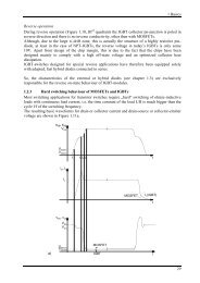
Figure 4: GTI (grid-tied inverter) efficiency at various power; switching frequency 5kHz<br />
If the generator voltage is lower than the<br />
sum of the series connected cells, the<br />
current from the generator will decline.<br />
More cells there<strong>for</strong>e have to be bypassed,<br />
reducing the number of series cells and<br />
increasing the generator current.<br />
PV applications<br />
PV applications usually have only one PE<br />
line-side grid-tie inverter (GTI). GTI AC<br />
output voltage is proportional to the<br />
minimum DC input voltage - the start-up<br />
PV voltage proportional to the minimum<br />
sunlight. If the chosen AC output voltage is<br />
lower, the currents <strong>for</strong> the rated power will<br />
be higher; at the same time, however, the<br />
start-up voltage will be lower. The AC<br />
output voltage is there<strong>for</strong>e a compromise:<br />
some products use 3 x 270V, while others<br />
use 3 x 328 V.<br />
The higher AC output voltage design<br />
neglects the minimum energy that could<br />
be used if the PV voltage / output AC<br />
voltage is lower. In a PV application, GTI<br />
operate at approximately 1/2 of the rated<br />
output voltage only; 1200V silicon is<br />
developed <strong>for</strong> input/output voltage of up<br />
to 480VAC, and PV applications today use<br />
just 270V...330V. The efficiency of such<br />
operation is lower, because it is strongly<br />
related to the modulation factor m,<br />
VAC/VDC ratio. For 400VAC/650VDC or<br />
480VAC/800VDC, the efficiency is very<br />
similar and higher than the ratio used in PV<br />
Figure 5: Voltage booster and GTI<br />
applications of 270VAC (500...900VDC)<br />
(see Figure 4).<br />
Described below is a power conversion<br />
scheme (Figure 5) <strong>for</strong> MW-class PV<br />
consisting of solar panels, an active frontend<br />
with symmetrical voltage boosters<br />
next to the solar panels, a DC transmission<br />
line to the inverter station, industrial gridside<br />
converter, sinusoidal filter, and<br />
standard line voltage / MV trans<strong>for</strong>mer.<br />
Inverter input voltage is optimized to the<br />
AC trans<strong>for</strong>mer input voltage, and the<br />
modulation factor m is close to 1<br />
according to equation 3:<br />
Sample application from the USA: Circuit<br />
from Figure 5 PV voltage is in the range of<br />
200V-600V; booster output voltage /<br />
transmission voltage is 800VDC; output:<br />
3x480V, a standard trans<strong>for</strong>mer is in use.<br />
600V Silicon is used <strong>for</strong> the front end, and<br />
1200V <strong>for</strong> the inverter. For a PV voltage of<br />
400V, <strong>for</strong> example, the DC transmission<br />
losses are four times lower, while the<br />
transmission voltage is 800V. The<br />
requirement is to have a relatively low<br />
ripple current from PV panels, and this can<br />
be achieved with higher inductance<br />
between the PV panels and the front-end<br />
unit, but also with increased switching<br />
frequency. The inductance of the<br />
www.power-mag.com