New Design Proposals for High Power Renewable Energy - Semikron
New Design Proposals for High Power Renewable Energy - Semikron
New Design Proposals for High Power Renewable Energy - Semikron

You also want an ePaper? Increase the reach of your titles
YUMPU automatically turns print PDFs into web optimized ePapers that Google loves.
ISSUE 4 – June 2010<br />
www.power-mag.com<br />
WIND & SOLAR POWER<br />
<strong>New</strong> <strong>Design</strong> <strong>Proposals</strong> <strong>for</strong><br />
<strong>High</strong>-<strong>Power</strong> <strong>Renewable</strong><br />
<strong>Energy</strong> Applications<br />
Also inside this issue<br />
Opinion | Market <strong>New</strong>s | PCIM 2010 Report |<br />
<strong>Renewable</strong> Energies: Solar <strong>Power</strong> | Wind <strong>Power</strong> |<br />
Products | Website Locator
24 WIND & SOLAR POWER www.semikron.com<br />
<strong>New</strong> <strong>Design</strong> <strong>Proposals</strong> <strong>for</strong><br />
<strong>High</strong>-<strong>Power</strong> <strong>Renewable</strong><br />
<strong>Energy</strong> Applications<br />
<strong>Renewable</strong> energy applications are a great challenge <strong>for</strong> <strong>Power</strong> Electronics, with efficiency and reliability<br />
being the prevailing requirements. Today, 1700V low-voltage Silicon is vastly superior. For input/output<br />
powers of several MW, dozens of modules with dozens of chips need to be connected in parallel. The best<br />
solution is paralleling inverters / power blocks, but such solutions require additional low-voltage<br />
transmission from the source to the medium-voltage (MV) trans<strong>for</strong>mer. An alternative solution is a MV<br />
source and transmission connected to MV grid-side inverter based on low-voltage Silicon - power blocks -<br />
connected in series. In addition, interleaved PWM reduces the size of the sinusoidal filter and the switching<br />
frequency, as well as the total losses. Dejan Schreiber, Senior Application Manager, <strong>Semikron</strong>,<br />
Nuremberg, Germany<br />
Existing new high-power renewable<br />
energy sources are wind turbines (WT)<br />
and photovoltaic (PV) applications. The<br />
average power of new WTs is over 2MW,<br />
but up to 5MW are also in use. As <strong>for</strong> PV,<br />
over the last few years, the trend has been<br />
to use individual units of up to 0.5MW,<br />
with an increasing tendency towards<br />
1MW+ per unit. Large PV systems of<br />
10MW are the most common and up to<br />
60MW are in operation. Both are<br />
connected to the grid through line-side<br />
inverters, and both supply the grid with<br />
low THD (total harmonic distortion)<br />
sinusoidal currents via sinusoidal filters.<br />
WTs have generator-side converters with<br />
boost features, rectifying the variable<br />
generator voltage to constant DC voltage<br />
required <strong>for</strong> optimal operation of the gridside<br />
converter. Similarly, PV panels supply<br />
converters with voltage proportional to<br />
sunlight intensity, ambient temperature,<br />
load current, and power. The result is a<br />
variable input voltage in the range of more<br />
than 1:2. Typically high-power PV grid-side<br />
inverters do not use additional front-end<br />
converters.<br />
<strong>Power</strong> converting efficiency is the No.1<br />
priority. Today, power electronics (PE) uses<br />
industrial Silicon-based components of<br />
1200V and 1700V <strong>for</strong> WTs and 1200V <strong>for</strong><br />
PV applications (600V <strong>for</strong> low-power<br />
single-phase supply). The system efficiency<br />
can be improved with reduced converter<br />
losses by using the right Silicon and new<br />
better semiconductors technologies. This<br />
article shall not, however, dwell on this <strong>for</strong><br />
the simple reason that IGBT’s will remain<br />
the work horse of power electronics <strong>for</strong> the<br />
next 5 to 10 years, with no notable<br />
changes to speak of.<br />
WT designs based on a doubly fed<br />
induction generator (DFIG) are going out<br />
of fashion. In fact, WT companies that<br />
employ DFIG technology are now basing<br />
their new developments on the full-size<br />
principle, the traditional 4-quadrant drive.<br />
WT converter efficiency today, <strong>for</strong> a full-size<br />
construction with two serial power<br />
electronics converters placed in one<br />
casing, and measured from the generator<br />
output through generator dv/dt filter,<br />
generator-side converter, DC link, grid-side<br />
inverter and output sinusoidal filter, is in<br />
the range of 96-97%. <strong>Power</strong> converter<br />
sizing is driven by price and high reliability<br />
requirements.<br />
Reliability is a very important factor. A<br />
wind turbine must not stop working, must<br />
not stop turning! First-rate components are<br />
there<strong>for</strong>e an absolute must. What is also<br />
important, however, is to have a turbine<br />
design which enables continued operation<br />
should an individual component fail. The<br />
large inverter powers in the range of<br />
several MVA require considerable<br />
quantities of semiconductor chips in<br />
parallel, and this is accomplished by<br />
paralleling modules.<br />
Solutions <strong>for</strong> parallel operation of<br />
IGBT modules<br />
1) One inverter phase unit is used <strong>for</strong> the<br />
entire power with one driver <strong>for</strong> many<br />
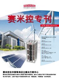
Figure 1: Turbine construction with three<br />
generator windings and independent<br />
drive trains<br />
Issue 4 2010 <strong>Power</strong> Electronics Europe<br />
www.power-mag.com
www.semikron.com WIND & SOLAR POWER 25<br />
www.power-mag.com<br />
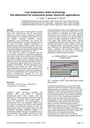
Figure 2: Per phase<br />
equivalent circuit of<br />
the line-side inverter<br />
and phasor diagrams<br />
<strong>for</strong> unity, leading,<br />
and lagging power<br />
factor operation<br />
IGBT modules in parallel. Each IGBT<br />
module has its own gate resistors and<br />
symmetrical DC & AC connections. One<br />
successful example is SEMIKUBE IGBT<br />
power STACK, <strong>for</strong> use in PV applications.<br />
2) Paralleling of several inverter-phase<br />
units, each with own driver operating in<br />
parallel. Due to different driver delay<br />
times, small AC output chokes are also<br />
required (paralleling of SKiiP IPM power<br />
stack).<br />
3) Paralleling of three-phase units with a<br />
DC link and several modules in parallel,<br />
driven by its own drivers. For higher<br />
power, several three-phase inverters are<br />
connected in parallel. Due to different<br />
driver delay times, AC output chokes<br />
are still needed. One PWM signal and<br />
one DC link are in use.<br />
4) Parallel operation of three-phase<br />
inverters with one PWM controller and<br />
additional control of load current<br />
sharing of parallelized inverters<br />
(sophisticated PWM control).<br />
5) Master-slave drivers with short delay<br />
times, driving the several modules<br />
connected in parallel. There is no need<br />
<strong>for</strong> any additional inductances, and in<br />
the event of damage to a<br />
semiconductor chip, only one module<br />
will be damaged.<br />
6) Parallel inverter operation with galvanic<br />
isolation on input or output side - is the<br />
operation in parallel of standard,<br />
independent basic units with different<br />
PWM and separate controllers.<br />
In some WT designs, the generator and<br />
the entire drive train, as well as the MV<br />
trans<strong>for</strong>mer, are placed in the nacelle. In<br />
these cases, the total weight of the nacelle<br />
is very high, but it’s the only way to make<br />
the transmission losses between the LV<br />
generator and the MV grid bearable. In<br />
other designs, the WT drive train is located<br />
at the bottom, at the base of the tower.<br />
<strong>Power</strong> transmission over that distance of<br />
about 100m is low-voltage, with high<br />
power losses and cost.<br />
Standard industrial Silicon-based IGBT<br />
modules of 1700V have to be used in<br />
parallel <strong>for</strong> one three-phase inverter of 1MW;<br />
the maximum available power of a single<br />
three-phase inverter today is 1.5MW.<br />
There<strong>for</strong>e, solutions with several generator<br />
windings facilitate parallelization of<br />
independent drive trains. At the same time,<br />
the reliability of this design is higher than that<br />
of designs with one high-power converter<br />
with the same number of modules<br />
connected in parallel (see Figure 1).<br />
WT generators<br />
Generator requirements such as minimum<br />
size, ripple torque, and short circuit torque,<br />
especially <strong>for</strong> low-speed, direct-drive<br />
generators, result in generator solutions<br />
with a number of phases, such as 2 or 3 x<br />
three-phase windings, or 6 x three-phase<br />
windings. Generators with poly-phase<br />
systems of 5 or 7 or more phases are not<br />
used, because of standard industrial threephase<br />
inverters and controllers. For<br />
generator sizes in the range of several MW,<br />
the traditional method is a medium-voltage<br />
output. MV inputs & outputs, however,<br />
require the use of MV PE components.<br />
State-of-the-art MV converters used on the<br />
grid side, with switching frequencies of<br />
several kHz, have a much lower efficiency<br />
and are far more expensive per kW.<br />
Additional requirements <strong>for</strong> renewable<br />
energy sources are: active power control,<br />
reactive power control, low-voltage ridethrough<br />
capability, as well as a requirement<br />
mentioned less often, namely operation<br />
under unsymmetrical grid voltages.<br />
Reactive power control <strong>for</strong> renewable<br />
energy sources, initially used in WTs, and<br />
more recently <strong>for</strong> PV applications, calls <strong>for</strong><br />
higher DC link voltage input to the line-side<br />
inverter.<br />
<strong>Power</strong> flow in the PWM converter is<br />
controlled by adjusting the phase shift<br />
angle between the source voltage U1<br />
and the respective converter reflected<br />
input voltage Vs1.<br />
When U1 leads Vs1 the real power<br />
flows from the AC source into the<br />
converter. Conversely, if U1 lags, Vs1<br />
power flows from the converter’s DC side<br />
into the AC source. The real power<br />
transferred is given by equation 1:<br />
The AC power factor is adjusted by<br />
controlling the amplitude of Vs1. The per<br />
phase equivalent circuit and phase<br />
diagrams of the leading, lagging and unity<br />
power factor operation is shown in Fig.2.<br />
The phasor diagram shows that to achieve<br />
a unity power factor, Vs1 has to be<br />
according to equation 2<br />
Proposal <strong>for</strong> series connection of high<br />
power WT inverter cells<br />
WT designs with full size converters based<br />
on separate generator windings have many<br />
advantages, but also one large drawback.<br />
Many cables are required between the<br />
generator and the converter - 3 x threephase<br />
winding set. All of these converters<br />
are there<strong>for</strong>e situated near the generator,<br />
in the nacelle. For high powers at low<br />
voltages, the generator currents are >><br />
1500A. An attractive solution is the MV<br />
synchronous generator and only a diode<br />
rectifier. However, in this case, the DC<br />
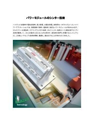
Figure 3: MV generator with MV grid-side inverter with several cells connected in series<br />
Issue 4 2010 <strong>Power</strong> Electronics Europe
26 WIND & SOLAR POWER www.semikron.com<br />
Issue 4 2010 <strong>Power</strong> Electronics Europe<br />
voltage variations are large (1:2) and<br />
require MV Silicon devices. As the WT is<br />
supposed to produce power even at<br />
minimal rotation speed and a minimal DC<br />
voltage, <strong>for</strong> instance <strong>for</strong> 1000VDC, the<br />
output voltage at the MV trans<strong>for</strong>mer is<br />
relatively low, i.e. 660V. At the same time,<br />
DC voltage may reach more than 2kV.<br />
A logical solution to the MV grid-side<br />
inverter is a string of series connected<br />
inverters, which can divide the variable<br />
rectified generator voltage. These grid-side<br />
inverter cells are connected to the primary<br />
windings of the MV line trans<strong>for</strong>mer, and<br />
independently maintain their DC link<br />
voltages. For lower generator voltages,<br />
some of the cells must be bypassed, so<br />
that the equivalent total voltage of the cells<br />
is lower and corresponds to the generator<br />
voltage. The WT torque requirement is the<br />
same as the generator current<br />
requirement; it is there<strong>for</strong>e compared with<br />
the real, actual value of the DC current. If<br />
the torque demand is higher than the<br />
actual current DC value, the sum of bypass<br />
times should be larger, more cells are<br />
bypassed and the equivalent counter-EMF<br />
will be lower, thus increasing DC current.<br />
Each of the grid-side inverters used<br />
controls and maintains constant input DC<br />
voltage, <strong>for</strong> instance 1000V, and is<br />
connected to the primary winding of the<br />
trans<strong>for</strong>mer. If the DC voltage is higher<br />
than a set value, the discharge currents will<br />
be larger. The grid-side inverters can be<br />
single- or three-phase units. Single-phase<br />
units have only one trans<strong>for</strong>mer winding.<br />
The rectified generator MV, <strong>for</strong> instance a<br />
dozen kV, supplies this string of inverter<br />
cells. Some cells have input bypass<br />
switches which allow <strong>for</strong> DC link control,<br />
and some cells can have no input bypass.<br />
They are always connected in series and<br />
the sum of their voltages corresponds to<br />
the minimum generator voltage.<br />
Described below is a power conversion<br />
scheme <strong>for</strong> MW-class wind turbines<br />
consisting of a medium-voltage<br />
synchronous generator, a diode rectifier in<br />
the nacelle, and an MV DC-efficient power<br />
transmission down to the MV line-side<br />
inverter and the high-voltage grid<br />
trans<strong>for</strong>mer (see Figure 3). Several cells<br />
that share the variable output generator<br />
voltage are also used. Each cell has a gridside<br />
inverter, three-phase or single-phase,<br />
separate trans<strong>for</strong>mer windings and DC link<br />
capacitors. The input power - the current<br />
from the MV generator - charges the DC<br />
link, and the converter discharges it. This is<br />
why the DC link voltage remains constant,<br />
because the grid-tie inverter controls the<br />
DC discharge current to the grid. The cell<br />
input features one half-bridge configuration,<br />
<strong>for</strong> instance a conventional booster; this<br />
operates, however, as a bypass switch only.<br />
Figure 4: GTI (grid-tied inverter) efficiency at various power; switching frequency 5kHz<br />
If the generator voltage is lower than the<br />
sum of the series connected cells, the<br />
current from the generator will decline.<br />
More cells there<strong>for</strong>e have to be bypassed,<br />
reducing the number of series cells and<br />
increasing the generator current.<br />
PV applications<br />
PV applications usually have only one PE<br />
line-side grid-tie inverter (GTI). GTI AC<br />
output voltage is proportional to the<br />
minimum DC input voltage - the start-up<br />
PV voltage proportional to the minimum<br />
sunlight. If the chosen AC output voltage is<br />
lower, the currents <strong>for</strong> the rated power will<br />
be higher; at the same time, however, the<br />
start-up voltage will be lower. The AC<br />
output voltage is there<strong>for</strong>e a compromise:<br />
some products use 3 x 270V, while others<br />
use 3 x 328 V.<br />
The higher AC output voltage design<br />
neglects the minimum energy that could<br />
be used if the PV voltage / output AC<br />
voltage is lower. In a PV application, GTI<br />
operate at approximately 1/2 of the rated<br />
output voltage only; 1200V silicon is<br />
developed <strong>for</strong> input/output voltage of up<br />
to 480VAC, and PV applications today use<br />
just 270V...330V. The efficiency of such<br />
operation is lower, because it is strongly<br />
related to the modulation factor m,<br />
VAC/VDC ratio. For 400VAC/650VDC or<br />
480VAC/800VDC, the efficiency is very<br />
similar and higher than the ratio used in PV<br />
Figure 5: Voltage booster and GTI<br />
applications of 270VAC (500...900VDC)<br />
(see Figure 4).<br />
Described below is a power conversion<br />
scheme (Figure 5) <strong>for</strong> MW-class PV<br />
consisting of solar panels, an active frontend<br />
with symmetrical voltage boosters<br />
next to the solar panels, a DC transmission<br />
line to the inverter station, industrial gridside<br />
converter, sinusoidal filter, and<br />
standard line voltage / MV trans<strong>for</strong>mer.<br />
Inverter input voltage is optimized to the<br />
AC trans<strong>for</strong>mer input voltage, and the<br />
modulation factor m is close to 1<br />
according to equation 3:<br />
Sample application from the USA: Circuit<br />
from Figure 5 PV voltage is in the range of<br />
200V-600V; booster output voltage /<br />
transmission voltage is 800VDC; output:<br />
3x480V, a standard trans<strong>for</strong>mer is in use.<br />
600V Silicon is used <strong>for</strong> the front end, and<br />
1200V <strong>for</strong> the inverter. For a PV voltage of<br />
400V, <strong>for</strong> example, the DC transmission<br />
losses are four times lower, while the<br />
transmission voltage is 800V. The<br />
requirement is to have a relatively low<br />
ripple current from PV panels, and this can<br />
be achieved with higher inductance<br />
between the PV panels and the front-end<br />
unit, but also with increased switching<br />
frequency. The inductance of the<br />
www.power-mag.com
www.semikron.com WIND & SOLAR POWER 27<br />
www.power-mag.com<br />
Figure 6: Voltage duplicator, second bypass or booster, two GTI with interleaved PWM<br />
connection cables have a positive<br />
influence on the reduction of the current<br />
ripple. A 100m long cable has an<br />
inductance of more than 0.1mH.<br />
Sample application from the EU: For a<br />
PV in the 400-900V range, the front<br />
booster will produce 650V <strong>for</strong> 3 x 400V, or<br />
800V <strong>for</strong> 3 x 480V. If the PV voltage is<br />
higher than 650V or 800V, the booster<br />
function is turned off and the PV voltage<br />
goes to the GTI unaltered.<br />
The front-end booster alternately<br />
supplies the upper and lower half of the<br />
output voltage, and when the top IGBT1<br />
and the bottom IGBT2 are turned-on <strong>for</strong><br />
half of the switching period, i.e. 180°<br />
electrics, it operates as a voltage duplicator.<br />
This method of operation has great<br />
advantages because the output current of<br />
the PV panel is constant and does not use<br />
additional high inductance L1 and L2. A<br />
connection cable length of 50-100m is<br />
sufficient. The scheme presented in Figure<br />
6 is used because of this advantage.<br />
The PV voltage is always doubled, i.e. it<br />
is in the range of 800V...1800V. As 1800V<br />
is too high <strong>for</strong> the low-voltage silicon used<br />
in the GTI, we can use the same idea as<br />
<strong>for</strong> MV wind turbines with two cells in<br />
series. The cell bypass circuit can be<br />
mounted near to the voltage duplicator<br />
and it can adjust the necessary DC voltage<br />
<strong>for</strong> two inverters in series. That way, the<br />
transmission voltage will be up to 4 times<br />
higher than the PV output voltage.<br />
Example 1: PV voltage 400V...900V;<br />
duplicator voltage 800...1800V; second<br />
booster output voltage/transmission<br />
voltage/inverter voltage: 1600V...1800V,<br />
without boosting effect after 1600V, <strong>for</strong> the<br />
trans<strong>for</strong>mer 2 x 3 x 480V. All switches in<br />
use are <strong>for</strong> 1200V.<br />
Example 2: PV voltage: 400...900V,<br />
duplicator voltage 800...1800V; second<br />
booster output voltage/transmission<br />
voltage/inverter voltage: 2200V=2x1100V,<br />
<strong>for</strong> the trans<strong>for</strong>mer 2 x 3x690V. Voltage<br />
duplicating silicon is <strong>for</strong> 1200V, and the<br />
remaining IGBTs & diodes are <strong>for</strong> 1700V.<br />
The inverter efficiency with 1700V silicon is<br />
higher than that <strong>for</strong> 1200V, if the carrier<br />
switching frequency is lower than 4kHz.<br />
For a 2200V transmission voltage, the<br />
transmission losses are 16 times lower<br />
than the losses of a classic, direct<br />
connection and a PV voltage of 550V<br />
Figure 7: Top-side inverter phase current; bottom-side inverter phase current, both with THD=19%<br />
and the grid current, with THD=3.8%; Filter inductance L_total=12%; Fsw=1kHz<br />
(using the same connection cables).<br />
The grid-side inverters, top and bottom<br />
side, have the same power and phase<br />
current values, and are connected to<br />
windings with galvanic insulation.<br />
Interleaving PWM can there<strong>for</strong>e be easily<br />
applied. For two inverters operating in<br />
parallel, the interleaved phase shifting is<br />
half of the switching period (i.e 180° el). In<br />
this way, the size of the sinusoidal filter,<br />
with only one inductance L, is significantly<br />
reduced. The simulation example in Figure<br />
7 shows inverter 1 and 2 currents, with a<br />
carrier switching frequency of 1kHz only<br />
and THD=19%, as well as the sum of<br />
these currents - the grid current, with very<br />
low THD=3.8%.<br />
The advantage of interleaving is clear.<br />
Only a low-pass filter with a single<br />
inductance, plus stray trans<strong>for</strong>mer<br />
inductance, corresponding to the short<br />
circuit trans<strong>for</strong>mer voltage uk=4%.<br />
L_total=12% is used. For a current THD<br />
below 4%, one grid-tie inverter with 12%<br />
inductance of the sinusoidal output filter<br />
needs a carrier switching frequency of<br />
more then 6 kHz.<br />
Conclusions<br />
WT power electronics are based exclusively<br />
on 1700V silicon IGBT & diodes. DFIG-WTs<br />
are becoming less popular, with current<br />
trends moving towards full-size<br />
configurations featuring two inverters<br />
connected back-to-back. WTs in<br />
development have powers in the range of<br />
3-5 MW. The principle with 2, 3 and even<br />
6 three-phase generator windings, using<br />
the same number of independent drive<br />
trains, with independent control, provides<br />
high modular power, as well as a<br />
redundant operation in case of a failure.<br />
The new design proposal <strong>for</strong> the WT is a<br />
MV generator with MV line-side inverter<br />
featuring a string of cells with bypass<br />
circuits and LV GTIs connected to<br />
independent MV trans<strong>for</strong>mer windings.<br />
PV applications are based on GTIs of up<br />
to 1MW of power, connected directly to<br />
the PV panels. For PV applications, the<br />
proposal aims <strong>for</strong> higher system efficiency,<br />
i.e. consists of a voltage duplicator and two<br />
cells in series, with 4 times higher<br />
transmission voltage and inverter operation<br />
with modulation factor 1, using interleaving<br />
in PWM control, to significantly reduce the<br />
output filter.<br />
Literature<br />
Dejan Schreiber: “<strong>High</strong>-<strong>Power</strong><br />
<strong>Renewable</strong> <strong>Energy</strong> Applications - Stateof-the-Art<br />
& <strong>New</strong> <strong>Design</strong> <strong>Proposals</strong>”, PEE<br />
Special Session “<strong>Power</strong> Electronics <strong>for</strong><br />
Efficient Inverters in <strong>Renewable</strong> <strong>Energy</strong><br />
Applications”, PCIM Europe 2010, May<br />
4, Room Paris<br />
Issue 4 2010 <strong>Power</strong> Electronics Europe