Download Instructions Here - Halfords
Download Instructions Here - Halfords
Download Instructions Here - Halfords

Create successful ePaper yourself
Turn your PDF publications into a flip-book with our unique Google optimized e-Paper software.
HALFORDS 12 FUNCTION<br />
CYCLE COMPUTER<br />
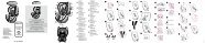
CONTENTS DESCRIPTIONS (See Fig. A)<br />
1. LCD DISPLAY 8.RUBBER SPACER<br />
2. MODE BUTTON 9. BRACKET<br />
3. BATTERY CAP 10. SENSOR<br />
4. SET BUTTON 11. MAGNET<br />
5. 1 st or 2 nd BIKE SELECTION BUTTON 12. MAGNET COLLAR<br />
6. CONTACTS 13. 1.5V BATTERY (LR44)<br />
7. SENSOR PAD 14. CABLE TIES<br />
15. MAGNET SCREW<br />
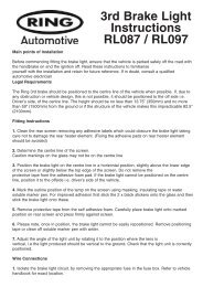
INSTALLATION<br />
SENSOR and MAGNET MOUNTING<br />
umeb12halfe2 # 英 文<br />
1. Mount the SENSOR on the front fork with the SENSOR PAD with the<br />
sensor facing the spokes. (See Fig. B)<br />
2. Mount the MAGNET on one spoke of the front wheel with the magnet<br />
facing and level with the SENSOR. (See Fig. C). Place the MAGNET<br />
COLLAR over the nut and check for alignment before firmly tightening<br />
the magnet screw .<br />
3. Adjust the relative position between the sensor and the magnet.<br />
Make sure the GAP between the magnet and the sensor is within 4mm (1/6<br />
inch). (See Fig. D)<br />
Adjust the gap by moving both the magnet and the sensor up or down.<br />
4. Do not cut off any excess sensor band until all adjustments have been made<br />
& correct computer operation has been checked and is functioning correctly.<br />
(See Fig. E)<br />
SECURING THE SENSOR CABLE<br />
1. Select suitable positions to clip the sensor cable<br />
to the fork with CABLE TIES. (See Fig. G)<br />
2. Make sure the sensor cable is loose enough for<br />
the handlebar to turn freely before tightening the<br />
cable ties.<br />
3. Secure excess wire near the fork crown by<br />
wrapping it around the front brake cable or by<br />
gathering excess cable and securing it with cable<br />
ties.<br />
MAIN UNIT MOUNTING<br />
Before mounting the main unit install<br />
battery-see battery installation/change<br />
1. Mount the main unit onto the bracket by sliding it<br />
from front to rear till it clicks into position. (See<br />
Fig. H)<br />
2. This bracket is designed with a lock lever. It can<br />
lock up the main unit, ensuring that the main unit<br />
will not drop out while riding.<br />
3. To remove the main unit, press down on the lock<br />
lever of the bracket then pull the main unit<br />
forward and off.<br />
FUNCTIONS<br />
SPD: Current Speed<br />
The current speed is always displayed on the upper set when riding. It<br />
displays current speed up to 199.9 Km/H or 120.0 Mile/H.<br />
ODO1, ODO2 Bike1 Odometer, Bike2 Odometer<br />
1. The odometer accumulates total distance as long as the cycle is being<br />
ridden.<br />
2. This computer design has 2 wheel circumference memories to calculate<br />
data for 2 bikes. The odometer is separate for each bike.<br />
3. It displays one ODO data only when the bike is selected in the current<br />
status.<br />
T-TM: Total Riding Time<br />
The T-TM accumulates total riding time while riding the bike1 or bike2.<br />
T-ODO: Total Odometer<br />
The T-ODO is the sum of the ODO1 plus ODO2.<br />
12HR or 24HR Clock<br />
Displays the current time either in 12HR or 24HRs.<br />
AVG: Average Speed<br />
1. This is calculated by dividing DST by the TM. The average data counted<br />
is from the last RESET to current point.<br />
2. It will display “0.0” when TM is less than 4 seconds.<br />
3. It is updated about one second when TM is over 4 seconds.<br />
4. It display an “Err” symbol when either the TM is over 100 hours or the<br />
DST is over 1.000 Km (or miles). Reset the unit in order to restart.<br />
DST: Trip Distance<br />
The DST function accumulates the distance data from the last RESET<br />
operation as long as the bike is being ridden.<br />
BRACKET MOUNTING<br />
Attached the bracket to the handlebar and fit with pad, use the two cable ties<br />
to mount the bracket, do not tighten the cable ties before the bracket is place<br />
at the right position.<br />
TM: Riding Time<br />
1. The TM totals the riding time from the last RESET operation.<br />
2. It will automatically begin counting upon riding, and continue to count for<br />
3 seconds after the cycle has stopped to confirm that no more signal is<br />
being sent.<br />
The computer reverses back the over counted 3 seconds automatically.<br />
3. It displays in 0.1 second increments when TM is less than 1 hour and<br />
changes to 1 second increments after 1 hour. It will restart from zero<br />
after 100 hours.<br />
MAX: Maximum Speed<br />
It shows the highest speed from the last RESET operation.<br />
DST/D: Distance Today<br />
The DST/D function accumulates the distance data for one day ride. The data<br />
will be cleared at PM 12.00.00 (0.00.00) automatically.<br />
/ : Speed Pacer<br />
The speed pacer arrow flashes up when the current speed is higher than the<br />
average speed and flashes down when lower than the average speed.
BUTTON OPERATION AND NORMAL OPERATION<br />
MODE BUTTON <br />
Press this button to move in loop sequence from one function screen to another.<br />
SET BUTTON <br />
Press this button to get in or out of the setting screens when you want to reset to<br />
bike1, bike2 circumference or the current time of the clock.<br />
1st or 2nd BIKE SELECTION BUTTON <br />
1. This computer has 2 sets of circumference memories to calculate 2 bikes data<br />
separately.<br />
2. Press 1 ST OR 2 ND BIKE SELECTION BUTTON to switch between bike1 and bike2.<br />
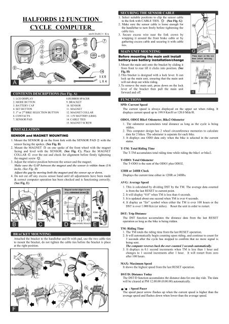
MAIN UNIT SET UP (ALL CLEAR)<br />
INITIATE THE COMPUTER & UNIT SELECTION (See Fig. 1)<br />
1. Install battery (refer to Battery Installation / Change).<br />
2. Hold down the MODE button and the 1 st or 2 nd BIKE SELECTION<br />
BUTTON simultaneously for more than 3 seconds to activate the computer<br />
and clear all data. IMPORTANT: Be sure to activate the computer before<br />
use otherwise the computer may run errors.<br />
3. All the LCD segments will be tested automatically after the unit is initiated.<br />
4. Press MODE button to stop LCD test, then the flashing “Km/h” is displayed<br />
for unit selection<br />
5. Press MODE button to choose Km/h or Mile/h.<br />
6. Press the SET BUTTON to store selection.<br />
2. Unit will change to<br />
the normal operation<br />
after the<br />
circumference is set.<br />
12 HR CLOCK<br />
SETTING (See Fig. 4)<br />
1. Press the MODE button until the display changes to “CLK”.<br />
2. Press the SET button to enter the clock adjusting screen.<br />
3. A quick press of the MODE button to select 12HR or 24HR.<br />
4. Adjust the clock data as the data setting procedures.<br />
RESET OPERATION (See Fig. 5)<br />
1. Hold down the MODE button until the LCD digit is cleared, then release it. The<br />
computer will reset the RT, MAX, AVG, and DST data from stored values to zero.<br />
2. It cannot reset CLK and ODO data.<br />
ODO1, ODO2 and T_TM DATA SETTING (See Fig. 2)<br />
1. The function is designed to re-key in former data of ODO1, ODO2 and T-TM<br />
when the battery is replaced. A new user does not need to set this data.<br />
2. Each press of the SET button skips one setting data process.<br />
3. Data setting Process:<br />
• The data is changed by adjusting each digit separately. The digit being changed<br />
flashes.<br />
• Quickly press the MODE button to increase the digital value by 1.<br />
• To change the setting digit, hold down the MODE button for more than 2 seconds.<br />
• Press the SET button to store the data and change to the next setting or the<br />
normal operation.<br />
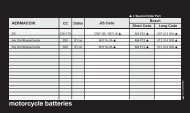
WHEEL CIRCUMFERENCE<br />
Identify the tyre size of your cycle and key in the corresponding number shown in the<br />
following chart.<br />
WHEEL CIRCUMFERENCE<br />
DATA SETTING (See Fig. 3)<br />
1. To set the correct wheel data quickly<br />
press the MODE button this will<br />
change the first digit one level at a time,<br />
when this number is correct hold down<br />
the MODE button for 3 seconds this<br />
will set the digit and move onto the next.<br />
Press the SET button to store the data.<br />
* Refer to the chart below to<br />
calculate the setting value.<br />
AUTOMATIC START/STOP<br />
1. The computer will automatically begin counting data upon riding and stop<br />
counting data when riding is stopped.<br />
2. The flashing symbol “ ” indicates that the computer is at start status.<br />
POWER AUTO ON/OFF<br />
To preserve battery power the computer will automatically switch off when it has not<br />
been used for approx. 4 mins. The computer will restart by either riding or pressing<br />
the MODE button .<br />
REPLACING THE BATTERY (See Fig. I)<br />
1. The Symbol “ ” will appear to indicate the<br />
battery is nearly exhausted.<br />
2. Replace the battery with a new one within 2 weeks<br />
after the symbol has appeared, otherwise incorrect<br />
data may be displayed.<br />
BATTERY INSTALLATION/CHANGE<br />
Note:- All data will be cleared when battery is replaced. This computer allows you to<br />
re-key in the ODO1, ODO2 and T-TM data which you rode before replacing the<br />
battery. So if wish to reinstall this information it should be recorded before removing the<br />
old battery.<br />
1. Remove the old battery.<br />
2. Replace with a new LR44 battery (See Fig. I) or equivalent in the compartment<br />
on the back of the computer with the positive (+) pole towards the battery cap.<br />
3. Activate the main unit again.<br />
TROUBLE SHOOTING<br />
Check the following before taking unit in for repairs.<br />
PROBLEM CHECK ITEMS REMEDY<br />
No Display 1. Is the battery dead?<br />
2. Is there incorrect battery<br />
installation?<br />
1. Replace the battery.<br />
2. Be sure that the positive pole of<br />
the battery is facing the battery cap.<br />
No current<br />
speed or<br />
incorrect<br />
data<br />
Irregular<br />
Display<br />
LCD is<br />
black<br />
Display is<br />
slow<br />
1. Is it at the recalibrating or<br />
12HR clock setting screen?<br />
2. Are the contacts between the<br />
main unit and bracket poor?<br />
3. Are the relative positions and<br />
gap of sensor and magnet<br />
correct?<br />
4. Is the wire broken?<br />
5. Is the circumference correct?<br />
Did you leave main unit under<br />
direct sunlight when not riding<br />
the bike for a long time.<br />
Is the temperature below 0 0 C<br />
(32 0 F)?<br />
1. Refer to the adjusting procedure<br />
and complete the adjustment.<br />
2. Wipe contacts clean.<br />
3. Refer to (FIG.C&D) and readjust<br />
data correctly.<br />
4. Repair or replace wire.<br />
5. Refer to “calibration” and enter<br />
correct value.<br />
Refer to the MAIN UNIT SETUP<br />
and activate the computer again.<br />
Place main unit in the shade to<br />
return to normal state.<br />
No adverse effect of data.<br />
Unit will return to normal state<br />
when the temperature rises.