Digiplex NE V1.3 DGPNE-96 Installation - Security Help Desk
Digiplex NE V1.3 DGPNE-96 Installation - Security Help Desk
Digiplex NE V1.3 DGPNE-96 Installation - Security Help Desk

Create successful ePaper yourself
Turn your PDF publications into a flip-book with our unique Google optimized e-Paper software.
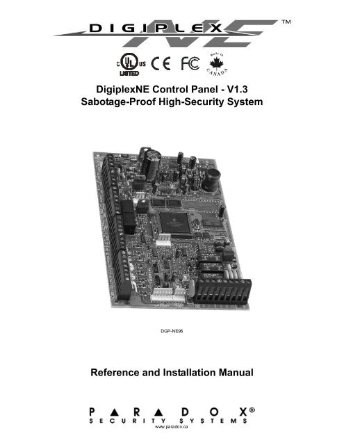
<strong>Digiplex</strong><strong>NE</strong> Control Panel - <strong>V1.3</strong><br />
Sabotage-Proof High-<strong>Security</strong> System<br />
DGP-<strong>NE</strong><strong>96</strong><br />
Reference and <strong>Installation</strong> Manual<br />
www.paradox.ca
TABLE OF CONTENTS<br />
1INTRODUCTION.................................................................................................................................................................... 6<br />
1.1 FEATURES.......................................................................................................................................................................................... 6<br />
1.2 SPECIFICATIONS ................................................................................................................................................................................. 6<br />
1.3 KEYPAD SPEC IFICATIONS .................................................................................................................................................................... 6<br />
2 INSTALLATION..................................................................................................................................................................... 7<br />
2.1 RECOMMENDED INSTALLATION PROCEDURE ........................................................................................................................................ 7<br />
2.2 LOCATION & MOUNTING...................................................................................................................................................................... 7<br />
2.3 EARTH GROUND................................................................................................................................................................................. 7<br />
2.4 AC POWER ........................................................................................................................................................................................ 7<br />
2.5 BACKUP BATTERY .............................................................................................................................................................................. 7<br />
2.5.1 Battery Test ....................................................................................................................................................................................................... 7<br />
2.6 AUXILIARY POWER TER MINALS............................................................................................................................................................ 7<br />
2.7 BELL/SIREN O UTPUT........................................................................................................................................................................... 7<br />
2.8 PROGRAMMABLE OUTPUTS ................................................................................................................................................................. 7<br />
2.9 KEYSWITCH CON<strong>NE</strong>CTIONS ................................................................................................................................................................. 7<br />
2.10 ACCESS CON TROL CON<strong>NE</strong>CTIONS..................................................................................................................................................... 7<br />
2.11 CALCU LATING POWER REQUIREMENTS .............................................................................................................................................. 9<br />
2.12 KEYPAD ZO<strong>NE</strong> CON<strong>NE</strong>CTIONS ......................................................................................................................................................... 10<br />
2.13 ADDRESSABLE ZO<strong>NE</strong> CON <strong>NE</strong>CTIONS................................................................................................................................................ 10<br />
2.14 DOUBLE ZON E CON<strong>NE</strong>CTION S......................................................................................................................................................... 11<br />
2.15 CON<strong>NE</strong>CTING THE DGP2-ZX4 ........................................................................................................................................................ 11<br />
2.16 BUS CON<strong>NE</strong>CTIONS ........................................................................................................................................................................ 12<br />
2.16.1 Connecting the Bus in Noisy Environments ................................................................................................................................................... 12<br />
2.17 FIR E CIR CUITS ............................................................................................................................................................................... 12<br />
2.17.1 Smoke Detector <strong>Installation</strong> (2-Wire)............................................................................................................................................................. 12<br />
2.17.2 ESL CleanMe® <strong>Installation</strong>............................................................................................................................................................................ 12<br />
2.17.3 Smoke Detector <strong>Installation</strong> (4-Wire)............................................................................................................................................................. 12<br />
2.18 TELEPHO<strong>NE</strong> LI<strong>NE</strong> CON<strong>NE</strong>CTIONS ..................................................................................................................................................... 12<br />
3PROGRAMMING METHODS.............................................................................................................................................. 14<br />
3.1 WINLOAD UPLOADING/DOWNLOADING SOF TWARE ............................................................................................................................. 14<br />
3.2 PARADOX MEMORY KEY................................................................................................................................................................... 14<br />
3.3 MODULE B ROAD CAST ....................................................................................................................................................................... 14<br />
3.4 PROGRAMMING THROUGH A KEYPAD................................................................................................................................................. 14<br />
3.4.1 Feature Select Programming........................................................................................................................................................................... 14<br />
3.4.2 Decimal Programming ..................................................................................................................................................................................... 14<br />
3.4.3 Hexadecimal Programming ............................................................................................................................................................................. 14<br />
3.5 MODULE P ROGRAMMING MOD E ........................................................................................................................................................ 14<br />
4ZO<strong>NE</strong> PROGRAMMING...................................................................................................................................................... 15<br />
4.1 ZO<strong>NE</strong> NUMBERING ............................................................................................................................................................................ 15<br />
4.2 ZO<strong>NE</strong> DOUBLING (ATZ) .................................................................................................................................................................... 16<br />
4.3 ZO<strong>NE</strong> DEFINITION S ........................................................................................................................................................................... 16<br />
4.3.1 Zone Disabled.................................................................................................................................................................................................. 16<br />
4.3.2 Entry Delays 1 and 2 ....................................................................................................................................................................................... 16<br />
4.3.3 Follow Zones ................................................................................................................................................................................................... 16<br />
4.3.4 Instant Zones ................................................................................................................................................................................................... 16<br />
4.3.5 24Hr Buzzer Zones ......................................................................................................................................................................................... 16<br />
4.3.6 24Hr Burglary Zones........................................................................................................................................................................................ 16<br />
4.3.7 24Hr Hold-up Zones ........................................................................................................................................................................................ 16<br />
4.3.8 24Hr Gas Zones .............................................................................................................................................................................................. 16<br />
4.3.9 24Hr Heat Zones ............................................................................................................................................................................................. 16<br />
4.3.10 24Hr Water Zones ......................................................................................................................................................................................... 16<br />
4.3.11 24Hr Freeze Zones ........................................................................................................................................................................................ 16<br />
4.3.12 Delayed 24Hr Fire Zone ................................................................................................................................................................................ 17<br />
4.3.13 Standard 24Hr Fire Zone............................................................................................................................................................................... 17<br />
4.3.14 Stay Delay Zone ............................................................................................................................................................................................ 17<br />
4.4 ZO<strong>NE</strong> P AR TITION A SSIG NMENT.......................................................................................................................................................... 17<br />
4.5 ZO<strong>NE</strong> O PT ION S................................................................................................................................................................................. 17<br />
4.5.1 Auto Zone Shutdown ....................................................................................................................................................................................... 17<br />
4.5.2 Bypas s Zones.................................................................................................................................................................................................. 17
4.5.3 Stay Zones....................................................................................................................................................................................................... 17<br />
4.5.4 Force Zones..................................................................................................................................................................................................... 17<br />
4.5.5 Alarm Types..................................................................................................................................................................................................... 18<br />
4.5.6 Intellizone......................................................................................................................................................................................................... 18<br />
4.5.7 Delay Before Alarm Transmission ................................................................................................................................................................... 18<br />
4.6 INPUT S PEED.................................................................................................................................................................................... 18<br />
4.7 EOL ON HARDWIRE ZO<strong>NE</strong>S............................................................................................................................................................... 18<br />
4.8 KEYPAD NU MBERING......................................................................................................................................................................... 18<br />
5KEYSWITCH PROGRAMMING........................................................................................................................................... 19<br />
5.1 KEYSWITCH NUMBERING ................................................................................................................................................................... 19<br />
5.2 KEYSWITCH DEFINITIONS................................................................................................................................................................... 19<br />
5.2.1 Keyswitch Disabled.......................................................................................................................................................................................... 19<br />
5.2.2 Momentary Keyswitch...................................................................................................................................................................................... 19<br />
5.2.3 Maintained Keyswitch ...................................................................................................................................................................................... 19<br />
5.2.4 PGM Activation (Utility Key)............................................................................................................................................................................. 20<br />
5.3 KEYSWITCH PARTITION ASSIGNMENT................................................................................................................................................. 20<br />
5.4 KEYSWITCH OPTIONS........................................................................................................................................................................ 20<br />
5.4.1 Stay/Instant Disarm Option (Keyswitch) .......................................................................................................................................................... 20<br />
5.4.2 Arm Only (Keyswitch) ...................................................................................................................................................................................... 20<br />
5.4.3 Regular Arming (Keyswitch) ............................................................................................................................................................................ 20<br />
5.4.4 Stay Arming (Keyswitch).................................................................................................................................................................................. 20<br />
5.4.5 Force Arming (Keyswitch)................................................................................................................................................................................ 20<br />
5.4.6 Instant Arming (Keyswitch).............................................................................................................................................................................. 20<br />
6ARMING & DISARMING OPTIONS..................................................................................................................................... 21<br />
6.1 ARMING FOLLOWS PARTITION............................................................................................................................................................ 21<br />
6.2 RESTRICT A RMING ON SUPERVISION LOSS ........................................................................................................................................ 21<br />
6.3 RESTRICT A RMING ON TAMPER ......................................................................................................................................................... 21<br />
6.4 RESTRICT A RMING ON AC FAILURE ................................................................................................................................................... 21<br />
6.5 RESTRICT A RMING ON BATTERY FAILURE .......................................................................................................................................... 21<br />
6.6 RESTRICT A RMING ON BELL OR AUXILIARY FAILURE........................................................................................................................... 21<br />
6.7 RESTRICT A RMING ON TLM FAILURE................................................................................................................................................. 21<br />
6.8 RESTRICT A RMING ON MODULE TROUBLES ........................................................................................................................................ 21<br />
6.9 TIMED AUTO-ARMING ........................................................................................................................................................................ 21<br />
6.9.1 Auto-Arm Timer ............................................................................................................................................................................................... 22<br />
6.10 NO MOVEMENT AUTO-ARMIN G ........................................................................................................................................................ 22<br />
6.10.1 No Movement Timer ...................................................................................................................................................................................... 22<br />
6.11 AUTO-ARMIN G O PT ION S.................................................................................................................................................................. 22<br />
6.12 SWITCH TO S TAY ARMING............................................................................................................................................................... 22<br />
6.13 FOLLOW ZO<strong>NE</strong> S WITCHES TO E NTRY DELAY 2................................................................................................................................. 22<br />
6.14 O<strong>NE</strong>-TOUCH FEATU RES................................................................................................................................................................... 22<br />
6.15 EXIT DELAY.................................................................................................................................................................................... 22<br />
6.15.1 Exit Delay Termination................................................................................................................................................................................... 22<br />
6.15.2 No Exit Delay on Remote Arm....................................................................................................................................................................... 22<br />
6.16 KEYPAD LOC K-OUT FEATURE .......................................................................................................................................................... 23<br />
6.17 BELL SQUAWK................................................................................................................................................................................ 23<br />
6.18 RIN G-BACK..................................................................................................................................................................................... 23<br />
6.19 MAXIMUM B YPASS ENTRIES ............................................................................................................................................................ 23<br />
6.20 DISPLAY “BYPASS” IF ARMED .......................................................................................................................................................... 23<br />
6.21 CLOSING DELIN QUENC Y .................................................................................................................................................................. 23<br />
7ALARM OPTIONS............................................................................................................................................................... 24<br />
7.1 BELL/ALARM O UTPUT ........................................................................................................................................................................ 24<br />
7.2 BELL CUT-OFF TIMER........................................................................................................................................................................ 24<br />
7.2.1 No Bell Cut-Off on Fire Alarm .......................................................................................................................................................................... 24<br />
7.2.2 Recycle Alarm Rate ......................................................................................................................................................................................... 24<br />
7.2.3 Recycle Delay .................................................................................................................................................................................................. 24<br />
7.3 WIRELESS TRANSMITTER SUPERVISION OPTIONS............................................................................................................................... 24<br />
7.3.1 Supervision Bypass Options ............................................................................................................................................................................ 24<br />
7.4 POLICE CODE TIMER......................................................................................................................................................................... 24<br />
7.5 TAMPER RECOGNITION OPTIONS....................................................................................................................................................... 24<br />
7.5.1 Tamper Bypass Options .................................................................................................................................................................................. 25<br />
7.6 KEYPAD PANIC O PT IONS ................................................................................................................................................................... 25
8EVENT REPORTING........................................................................................................................................................... 26<br />
8.1 REPORTING E NABLED....................................................................................................................................................................... 27<br />
8.2 REPORT CODES............................................................................................................................................................................... 27<br />
8.2.1 Zone Alarm and Alarm Restore Report Codes ................................................................................................................................................ 27<br />
8.2.2 Tamper and Tamper Restore Report Codes ................................................................................................................................................... 27<br />
8.2.3 Keyswitch Arming ............................................................................................................................................................................................ 27<br />
8.2.4 Keyswitch Disarming ....................................................................................................................................................................................... 27<br />
8.2.5 Access Codes Arming ..................................................................................................................................................................................... 27<br />
8.2.6 Access Codes Disarming................................................................................................................................................................................. 27<br />
8.2.7 Special System Reporting Codes .................................................................................................................................................................... 27<br />
8.2.8 Special Arming Report Codes ......................................................................................................................................................................... 27<br />
8.2.9 Special Disarming Report Codes ..................................................................................................................................................................... 28<br />
8.2.10 Special Alarm Report Codes ......................................................................................................................................................................... 28<br />
8.2.11 System Trouble Codes .................................................................................................................................................................................. 28<br />
8.2.12 System Trouble Restore Codes ..................................................................................................................................................................... 28<br />
8.3 REPORT A RMING AND DISARMING ..................................................................................................................................................... 28<br />
8.3.1 Enable Arming and Disarming Report Schedules ........................................................................................................................................... 28<br />
8.3.2 Arming and Disarming Report Schedules ........................................................................................................................................................ 29<br />
8.3.3 Arming/Disarming Schedule Tolerance Window ............................................................................................................................................. 29<br />
8.4 MONITORIN G S TATION P HON E #........................................................................................................................................................ 29<br />
8.5 PARTITION ACCOUNT # ..................................................................................................................................................................... 29<br />
8.6 REPORTING FORMATS ...................................................................................................................................................................... 29<br />
8.6.1 Standard Pulse Formats .................................................................................................................................................................................. 30<br />
8.6.2 Ademco Express.............................................................................................................................................................................................. 30<br />
8.6.3 Contact ID Pager ............................................................................................................................................................................................. 30<br />
8.6.4 Ademco Contact ID.......................................................................................................................................................................................... 30<br />
8.6.5 SIA FSK ........................................................................................................................................................................................................... 30<br />
8.6.6 Pager Reporting Format .................................................................................................................................................................................. 30<br />
8.7 EVENT CALL DIRECTION ................................................................................................................................................................... 30<br />
8.7.1 Maximum Dialing Attempts .............................................................................................................................................................................. 30<br />
8.7.2 Delay Between Dialing Attempts ..................................................................................................................................................................... 30<br />
8.7.3 Alternate Dialing Option................................................................................................................................................................................... 30<br />
8.8 PAGER DELAY.................................................................................................................................................................................. 30<br />
8.9 RECENT CLOSE DELAY..................................................................................................................................................................... 30<br />
8.10 POWER FAILURE REPORT DELAY.................................................................................................................................................... 31<br />
8.11 AUTO TEST REPORT....................................................................................................................................................................... 31<br />
8.12 DISARM REPORTING OPTIONS......................................................................................................................................................... 31<br />
8.13 ZO<strong>NE</strong> RESTORE REPO RT OPTIONS.................................................................................................................................................. 31<br />
8.14 AUTO REPORT COD E PROGRAMMING.............................................................................................................................................. 31<br />
9DIALER OPTIONS............................................................................................................................................................... 32<br />
9.1 TELEPHO<strong>NE</strong> LI<strong>NE</strong> MONITORING.......................................................................................................................................................... 32<br />
9.1.1 TLM Fail Timer................................................................................................................................................................................................. 32<br />
9.2 TO<strong>NE</strong>/PU LSE DIALING........................................................................................................................................................................ 32<br />
9.3 PULSE RATIO ................................................................................................................................................................................... 32<br />
9.4 BUSY TON E DETECTION.................................................................................................................................................................... 32<br />
9.5 SWITCH TO P ULSE ........................................................................................................................................................................... 32<br />
9.6 BELL ON COMMUNIC ATION FAIL ........................................................................................................................................................ 32<br />
9.7 KEYPAD BEEP ON SUCC ESSFU L ARM OR DISARM REPORT................................................................................................................. 32<br />
9.8 DIAL TO<strong>NE</strong> DELAY ............................................................................................................................................................................ 32<br />
10PROGRAMMABLE OUTPUTS .......................................................................................................................................... 33<br />
10.1 PGM ACTIVATION EVENT ............................................................................................................................................................... 33<br />
10.2 PGM DEACTIVATION OPTION.......................................................................................................................................................... 33<br />
10.3 FLEXIBLE PGM DEACT IVAT ION OPTION........................................................................................................................................... 33<br />
10.4 PGM DEACTIVATION EVENT ........................................................................................................................................................... 33<br />
10.5 PGM TIMER................................................................................................................................................................................... 33<br />
10.5.1 PGM Time Base Selection............................................................................................................................................................................. 33<br />
10.6 PGM1 BECOMES A 2-WIRE SMOKE DETECTOR INPUT...................................................................................................................... 33<br />
10.7 PGM TEST MODE .......................................................................................................................................................................... 33<br />
11SYSTEM SETTINGS & COMMANDS................................................................................................................................ 34<br />
11.1 HARDWARE RESET......................................................................................................................................................................... 34<br />
11.2 SOFTWARE RESET.......................................................................................................................................................................... 34<br />
11.3 INSTALLER CODE L OCK................................................................................................................................................................... 34
11.4 DAYLIGHT S AVINGS TIME ................................................................................................................................................................ 34<br />
11.5 BATTERY CHARGE CURRENT........................................................................................................................................................... 34<br />
11.6 BUS SPEED .................................................................................................................................................................................... 34<br />
11.7 TRANSMIT ZON E STATU S ON SERIAL P ORT ...................................................................................................................................... 34<br />
11.8 SERIAL PORT BAUD RATE............................................................................................................................................................... 34<br />
11.9 PARTITIONING................................................................................................................................................................................. 34<br />
11.9.1 Panel Partition Assignment............................................................................................................................................................................ 35<br />
11.10 SHABBAT FEATURE ....................................................................................................................................................................... 35<br />
11.11 INSTALLER FUNCTION KEYS........................................................................................................................................................... 35<br />
11.12 MODULE RESET............................................................................................................................................................................ 35<br />
11.13 LOCATE MOD ULE .......................................................................................................................................................................... 35<br />
11.14 MODULE P ROGRAMMING ............................................................................................................................................................... 35<br />
11.15 MODULE AND LABEL BROADCAST .................................................................................................................................................. 35<br />
11.16 SYSTEM DATE & TIME................................................................................................................................................................... 36<br />
11.17 CLOCK COMPENSATION V ALU E...................................................................................................................................................... 36<br />
11.18 REMOVE MODULE ......................................................................................................................................................................... 36<br />
11.19 SERIAL NUMBER VIEWING ............................................................................................................................................................. 36<br />
11.20 POWER SAVE MODE..................................................................................................................................................................... 36<br />
11.21 AUTO TROUBLE SHU TDOWN.......................................................................................................................................................... 36<br />
11.22 NO AC FAIL DISPLAY .................................................................................................................................................................... 36<br />
11.23 MULTIPLE ACTION FEATURE.......................................................................................................................................................... 36<br />
11.24 SYSTEM LABELS........................................................................................................................................................................... 36<br />
12ACCESS CODES............................................................................................................................................................... 38<br />
12.1 INSTALLER CODE ............................................................................................................................................................................ 38<br />
12.2 ACCESS COD E LENGTH................................................................................................................................................................... 38<br />
12.3 SYSTEM MASTER CODE .................................................................................................................................................................. 38<br />
12.4 PROGRAMMING A CCESS CODES...................................................................................................................................................... 38<br />
12.5 USER OPTIONS............................................................................................................................................................................... 38<br />
12.6 PARTITION ASSIGNMENT.................................................................................................................................................................. 39<br />
12.7 ACCESS CON TROL .......................................................................................................................................................................... 39<br />
12.7.1 Access Level Assignment.............................................................................................................................................................................. 39<br />
12.7.2 Schedule Assignment.................................................................................................................................................................................... 39<br />
12.7.3 Access Control Options ................................................................................................................................................................................. 39<br />
12.7.4 Access Card Assignment............................................................................................................................................................................... 39<br />
13ACCESS CONTROL: SYSTEM FEATURES..................................................................................................................... 40<br />
13.1 COMMON ACCESS CONTROL TERMS................................................................................................................................................ 40<br />
13.2 PROGRAMMING O VERVIEW .............................................................................................................................................................. 40<br />
13.3 ENABLE ACCESS CON TROL ............................................................................................................................................................. 40<br />
13.4 DOOR NUMBERING.......................................................................................................................................................................... 40<br />
13.5 ACCESS LEVELS............................................................................................................................................................................. 40<br />
13.6 ACCESS SCH ED ULES....................................................................................................................................................................... 40<br />
13.7 BACKUP SCH ED ULES....................................................................................................................................................................... 41<br />
13.8 HOLIDAY PROGRAMMING................................................................................................................................................................. 41<br />
13.9 SCHEDU LE TOLERANCE WINDOW .................................................................................................................................................... 41<br />
13.10 DOOR ACCESS MODE................................................................................................................................................................... 41<br />
13.11 CODE A CCESS.............................................................................................................................................................................. 41<br />
13.12 CARD AND CODE ACCESS............................................................................................................................................................. 41<br />
13.13 SKIP EXIT DELAY WHEN ARMIN G WITH ACC ESS CARD................................................................................................................... 42<br />
13.14 RESTRICT A RMING ON DOOR......................................................................................................................................................... 42<br />
13.15 RESTRICT DISARMING ON DOOR.................................................................................................................................................... 42<br />
13.16 DOOR ACCESS DURIN G CLOCK LOSS............................................................................................................................................ 42<br />
13.17 BURGLAR ALARM ON FORCED DOOR OR DOOR L EF T O PEN ........................................................................................................... 42<br />
13.18 LOGGING ACCESS CON TROL EVENTS ............................................................................................................................................ 42<br />
13.18.1 Log Request For Exit In Event Buffer .......................................................................................................................................................... 42<br />
13.18.2 Log Door Left Open Restore In Event Buffer............................................................................................................................................... 42<br />
13.18.3 Log Door Forced Open Restore In Event Buffer .......................................................................................................................................... 42<br />
14WINLOAD SOFTWARE ..................................................................................................................................................... 43<br />
14.1 PA<strong>NE</strong>L IDENTIFIER........................................................................................................................................................................... 43<br />
14.2 PC PASSWORD............................................................................................................................................................................... 43<br />
14.3 PC TELEPHO<strong>NE</strong> NUMBER ................................................................................................................................................................ 43<br />
14.4 CALL BACK FEATURE ...................................................................................................................................................................... 43
14.5 CALL WINLOAD .............................................................................................................................................................................. 43<br />
14.6 ANSWER WINLOAD......................................................................................................................................................................... 43<br />
14.7 ANSWERING MACH I<strong>NE</strong> OVERRIDE DELAY......................................................................................................................................... 43<br />
14.8 RIN G COUNTER .............................................................................................................................................................................. 43<br />
14.9 EVENT B UFFER TRANSMISSION....................................................................................................................................................... 43<br />
15USER FEATURES ............................................................................................................................................................. 44<br />
15.1 REGULAR A RMING .......................................................................................................................................................................... 44<br />
15.2 STAY ARMING................................................................................................................................................................................. 44<br />
15.2.1 Stay Arming with Delay .................................................................................................................................................................................. 44<br />
15.3 INSTANT A RMING ............................................................................................................................................................................ 44<br />
15.3.1 Instant Arming with Delay .............................................................................................................................................................................. 44<br />
15.4 FORCE A RMING .............................................................................................................................................................................. 44<br />
15.5 DISARMING..................................................................................................................................................................................... 44<br />
15.6 BYPASS PROGRAMMING.................................................................................................................................................................. 44<br />
15.7 CHIME ZO<strong>NE</strong>S ................................................................................................................................................................................ 44<br />
15.8 KEYPAD SETTIN GS ......................................................................................................................................................................... 44<br />
15.9 EVENT RECORD DISPLAY................................................................................................................................................................ 45<br />
15.10 SCROLL RESTART......................................................................................................................................................................... 45<br />
15.11 TROUBLE DISPLAY........................................................................................................................................................................ 45<br />
15.12 TROUBLE L AT CH........................................................................................................................................................................... 45<br />
15.13 CLEAR BELL CURRENT LIMIT TROUBLE ......................................................................................................................................... 46<br />
16APPENDIX 1: PGM PROGRAMMING TABLE................................................................................................................... 47<br />
17APPENDIX 2: AUTOMATIC REPORT CODE LIST ........................................................................................................... 53<br />
18APPENDIX 3: CONTACT ID REPORT CODE LIST .......................................................................................................... 55<br />
19INDEX ................................................................................................................................................................................ 56<br />
20WARNINGS........................................................................................................................................................................ 63<br />
1.0
1 INTRODUCTION<br />
The integrity of a security system relies not only in the performance of the<br />
control panel, keypads, motion detectors and other accessories, but in the<br />
ability to communicate informat ion eff ectively back and forth t hrough the<br />
system's wiring. With this in mind Paradox <strong>Security</strong> Systems created the<br />
next evolution in control panel technology: <strong>Digiplex</strong><strong>NE</strong>. <strong>Digiplex</strong><strong>NE</strong> uses<br />
GuardWall Technology, a specialized encrypt ed communication protocol t o<br />
transmit dat a efficiently between the control panel and all its modules<br />
simult aneously and continuously. Since data is constant ly transmitted<br />
through the 4-wire communication bus, any at tempt to tamper with or<br />
disable any module or the wiring is immediately recognized and causes an<br />
alarm to be reported whether the system is armed or not.<br />
<strong>Digiplex</strong><strong>NE</strong> also offers the additional benefit of an innovative built-in access<br />
control system. Manage, control and monitor the traffic of up to 999 users<br />
through 32 secured areas by defining the days and times they are allowed<br />
access. By integrating access control and security, <strong>Digiplex</strong><strong>NE</strong> provides the<br />
best of both worlds in a feature-rich and user-friendly system.<br />
Beyond offering high security, Guardwall technology makes installing and<br />
programming ef fortless by eliminat ing t he need for home run wiring,<br />
jumpers and EOL resistors. Connect the modules with GuardWall<br />
technology in any order anywhere on t he communication bus and assign<br />
the zones as desired. Since programming a large security system through a<br />
keypad can be t ime consuming and tedious, installers can use t he WinLoad<br />
software to complete all the programming remotely, including setting a<br />
motion detector's sensitivity. Even users can modify their security system<br />
through the comfort of their own computer with <strong>NE</strong>ware, a simple, intuitive<br />
interf ace designed to add employees, set schedules, assign access rights,<br />
view the status of the system and all its modules and more.<br />
CTR-21 APPROVAL<br />
The <strong>Digiplex</strong><strong>NE</strong> control panel (DG P-<strong>NE</strong><strong>96</strong>) meets the European Union<br />
Common Technical Requirement CTR-21. The CTR-21 requirement is an<br />
elect rical standard that def ines the analogue interface for all t wo-wire<br />
telecommunications equipment (i.e. DECT, PABXs, etc.) intended for<br />
connection to the Public Switched Telephone Network. This allows the<br />
<strong>Digiplex</strong><strong>NE</strong> control panel t o be used in as many as 19 countries, such as<br />
Belgium, Germany, Greece, Portugal, Sweden and Switzerland.<br />
<strong>Digiplex</strong><strong>NE</strong> control panels with the CTR-21 approval are available as an<br />
option only.<br />
1.1 F EATURE S<br />
<br />
<br />
<br />
<br />
<br />
<br />
<br />
<br />
<br />
<br />
<br />
<br />
<br />
GuardWall technology:<br />
• Digital communication bus<br />
• Provides constant power, supervision and two-way communication<br />
bet ween the control panel and all its modules<br />
• Supports up to 127 modules<br />
• Connect modules up to 3000ft (914m) from the panel<br />
• Sabotage-proof technology without additional wiring<br />
<strong>96</strong> addressable zones<br />
8 partitions<br />
998 user codes, 1 System Master code and 1 installer code<br />
Built-in access control<br />
2048 stored events<br />
1 telephone line and optional secondary telephone line<br />
Remote diagnostics and pager messaging<br />
False alarm prevention f eat ures<br />
32 independent keyswitch zones (does not use any of the <strong>96</strong> zones)<br />
8 on-board hardwired input terminals<br />
3 on-board fully programmable outputs (PGMs):<br />
• 1 normally open, high-current transist or output (100mA)<br />
• 2 normally open or normally closed 5A programmable relay outputs<br />
• Up t o 32 more PGM input s t hrough the Keyswit ch’s PGM I nput<br />
feature<br />
PGM1 can be set as a two-wire smoke detector input<br />
<br />
Event report ing:<br />
• a separate dialing sequence for each partition<br />
• 4 Monitoring Station Telephone Numbers<br />
• SIA, Contact ID, Ademco Contact ID Edition 2000, Pager Format<br />
and many more communicator formats<br />
1.2 SPEC IFIC A TION S<br />
CON TROL P A<strong>NE</strong>L (NON-UL SYSTEMS)<br />
AC Power:<br />
16Vac, 20/40VA, 50-60Hz<br />
Battery:<br />
12Vdc, 4Ah minimum<br />
Auxiliary Power: 12Vdc 600mA typical, 700mA maximum,<br />
fuseless shutdown at 1.1A<br />
Bell Output:<br />
1A, fuseless shutdown @ 3A<br />
PG M Output :<br />
PGM1 (100mA), PGM2 and PG M3 (5A relay)<br />
Event Buffer:<br />
2048 events<br />
All control panel out puts are rat ed to operate bet ween 10.8Vdc and<br />
12.1Vdc<br />
CON TROL P A<strong>NE</strong>L (UL COMPLIAN T SYSTEMS)<br />
AC Power:<br />
16Vac, 40VA, 60Hz<br />
Battery:<br />
12Vdc, 4Ah minimum<br />
Auxiliary Power: 11.4 to 12.5Vdc, 200mA maximum, fuseless<br />
shutdown at 1. 1A<br />
Bell Output: 11.4 to 12.5Vdc, 1A maximum, fuseless<br />
shutdown @ 3A<br />
PG M Output :<br />
PGM1 (100mA), PGM2 and PG M3 (5A relay)<br />
Event Buffer:<br />
2048 events<br />
All control panel outputs are rated to operate between 11.4Vdc and<br />
12.5Vdc<br />
1.3 KE YPAD SPE CI FI CA TIO NS<br />
Power input:<br />
9-16 Vdc<br />
Typ. current consumption: 60mA (DGP2-641)<br />
150mA (DGP2-641AC)<br />
PGM current limit: 50 mA<br />
Number of inputs: 1 (DGP2-641)<br />
2 (DGP2-641AC)<br />
Power indication: Yellow LED on<br />
Locate indication: Green and yellow LEDs flash simultaneously<br />
Bus fault indication: Red and yellow LEDs flash alternately<br />
Tamper Switch: Yes (also used to deactivate locate)<br />
LCD:<br />
Super Twisted Nematic display (STN), wide<br />
viewing angle, 2 lines of 16 characters,<br />
adjustable scrolling speed, backlight and<br />
contrast<br />
Specifications may change without prior notice.<br />
UL Note: The DGP-<strong>NE</strong><strong>96</strong> control panel has only been tested with the LCD<br />
and Access Control LCD Keypads (DGP2-641 / DGP2-641AC)<br />
6 REFERENCE & INSTALLATION MANUAL
2 INSTALLATION<br />
2.1 RECOMMENDED INSTALLATION PROCEDURE<br />
This procedure is recommended t o facilitat e installation by verifying t he<br />
wiring at diff erent stages instead of only at t he end.<br />
Step 1: Install the cont rol panel.<br />
Step 2: Connect a portion of the system’s modules, including a keypad, to<br />
the communicat ion bus.<br />
Step 3: Connect the battery and then connect the AC power. Only the Clock<br />
Loss trouble should appear.<br />
Step 4: Disconnect AC power and the battery.<br />
Step 5: Continue the installation by following steps 2, 3 and 4.<br />
Step 6: Once the installation is complete, enter section [4000] to verify if all<br />
the modules’ serial numbers appear (see sect ion 11. 19 on page<br />
36). If modules were removed from the communication bus, enter<br />
[4005] t o remove t hem f rom the panel’s memory (see section 11. 18<br />
on page 36).<br />
Step 7: Connect an LCD Keypad at various points farthest from the control<br />
panel and use t he keypad’s built-in Voltmeter to verify t he<br />
communication bus’s voltage (refer to the <strong>Digiplex</strong>/<strong>Digiplex</strong><strong>NE</strong> LCD<br />
Keypad and Access Control LCD Keypad Reference & <strong>Installation</strong><br />
Manual).<br />
2.2 LOCATION & MOUNTING<br />
Before mounting the cabinet, push the five white nylon mounting studs into<br />
the back of the cabinet. Pull all cables int o the cabinet and prepare them for<br />
connection before mounting the circuit board int o the back of t he cabinet.<br />
Select an installat ion site that is not easily accessible to intruders and leave<br />
at least 2" around the panel box to permit adequate ventilation and heat<br />
dissipation. The installation site should be dry and close to an AC source,<br />
ground connection and telephone line connect ion.<br />
2.3 EAR TH GROUND<br />
Connect the zone and dialer ground terminals from the control panel to the<br />
enclosure and cold water pipe or grounding rod as per local electrical codes.<br />
For maximum lightning protection, use separate earth grounds<br />
for the zone and dialer grounds (see Figure 2-3 on page 8).<br />
2.4 AC POWER<br />
Use a 16.5Vac (50/60Hz) transf ormer with a minimum 20VA rat ing to<br />
provide suff icient AC power. For increased power use a transformer with a<br />
40VA rating. For UL Listed systems, use model #BE156240CAA. For CSA<br />
listed systems, use model #BE116240AAA. Do not use any switchcontrolled<br />
outlets to power the transformer. Connect the transformer as<br />
shown in Figure 2-3 on page 8.<br />
Do not connect the transformer or the backup battery until all<br />
wiring is completed.<br />
PLEASE NOTE: When powering up the DGP-<strong>NE</strong><strong>96</strong> control<br />
panel (V1.02 or higher), the panel will begin a module scan to<br />
verify if all the modules connected to the control panel are<br />
operational. The scanning process will take between 30 and<br />
120 seconds to complete depending on the number of<br />
modules connected to the control panel. The module scan is<br />
complete when the keypad begins to show the partition status.<br />
Only after the module scan is complete will the control panel<br />
be fully operational.<br />
2.5 BACKUP BATTERY<br />
To provide power during power loss, connect a 12Vdc 4Ah rechargeable<br />
acid/lead or gel cell backup bat tery (YUASA model #NP7-12<br />
recommended) as shown in Figure 2-3 on page 8. Connect the backup<br />
battery after applying AC power. When installing, verify proper polarity, as<br />
reversed connections will blow the batt ery fuse. For details on how to set<br />
the Battery Charge Current to either 350mA or 700mA, see section 11.5.<br />
2.5.1 Battery Test<br />
The control panel conducts a dynamic battery test under load every 64<br />
seconds. If the battery is disconnected, if its capacity is too low or if the<br />
battery voltage drops to 10.5 volts or less when there is no AC, the “Battery<br />
Trouble” message will appear in the Trouble Display. At 8.5 volts, the panel<br />
shuts down and all outputs close.<br />
2.6 AUX ILIA R Y POWER TERMINALS<br />
The auxiliary power supply can power the motion detect ors, keypads and<br />
other accessories in the security system. A fuseless circuit protects the<br />
auxiliary output against current overload and automatically shuts down if<br />
the current exceeds 1.1A. Auxiliary power will resume once the overload<br />
condition has restored. For details on available output power, please ref er<br />
to Figure 2-3 on page 8. To calculate power consumption, see Calculating<br />
Power Requirements on page 9.<br />
2.7 BELL/SIREN OUTPUT<br />
The BELL+ and BE LL- t erminals power bells and/or ot her warning devices<br />
t hat require a steady voltage output during an alarm. The bell out put<br />
supplies 12Vdc upon alarm and can support one 30-wat t or two 20-wat t<br />
sirens. The bell output uses a fuseless circuit and will automatically shut<br />
down if the current exceeds 3A. If the load on the BE LL terminals returns to<br />
normal (≤3A), the control panel will re-instat e power t o the BELL terminals.<br />
When connecting sirens, please verify correct polarity as shown in Figure<br />
2-3. PGM2 and PGM3 are relays rated at 5A each and can be used to<br />
power bells and/ or other warning devices by programming them as a bell/<br />
siren outputs (see section 10 on page 33).<br />
When the bell output is not used, the “Bell Absent” message<br />
appears in the Trouble Display. To avoid this, connect a 1kΩ<br />
resistor across the bell output. UL Note: The keypads must be<br />
programmed to beep with all troubles<br />
2.8 PROGRAMMABLE OUTPUTS<br />
The control panel comes standard with Figure 2-1: PGM & Relay<br />
PGM1 to PGM3. When a specific event or<br />
condition occurs in the system, a PGM can<br />
be programmed to reset smoke detectors,<br />
activat e st robe lights, open/close garage<br />
doors and much more. For details on how to<br />
program the PGMs, refer to section 10.<br />
PGM1 is 100mA (max.) normally open<br />
out put . PGM2 and PGM3 are 5A relay<br />
outputs that can be normally open or<br />
normally closed. If the current draw on<br />
PGM1 is to exceed the current output, we<br />
recommend using a relay as shown in<br />
Figure 2-1. PGM1 can be programmed as a<br />
2-wire smoke detect or input (see section<br />
2.17.1 on page 12 and section 10.6 on page 33).<br />
2.9 KEYS WITCH C ON<strong>NE</strong>CTIONS (NO T VERIFIED BY UL)<br />
Connect the keyswitches to the keypad,<br />
cont rol panel, or Zone Expansion Module's<br />
hardwired input terminals as shown in Figure<br />
2-2. Once a keyswitch is connected, it must be<br />
assigned a keyswitch zone and its parameters<br />
must be defined as described in Keyswitch<br />
Programming on page 19.<br />
2.10 ACCESS CONTRO L CO NN E CTIO NS<br />
Figure 2-2: Keysw itch<br />
For all access control explanations and connect ion drawings, refer to<br />
Access Control: System Features on page 40.<br />
DIGIPLEX<strong>NE</strong> CONTROL P A<strong>NE</strong>L 7
Figure 2-3: <strong>Digiplex</strong><strong>NE</strong> Control Panel Wiring Diagram<br />
On UL listed systems, all outputs are Class 2 or power-limited, except<br />
for th e battery te rmina l. The Cl ass 2 and po wer-l imited fire a larm circui ts<br />
sh all b e in sta lle d usin g CL 3, CL3 R, CL3 P, o r substitute cab le p ermitted<br />
by the National Electrical Code, ANSI/NFPA 70.<br />
This e qui pmen t sh oul d be instal led in accord ance with C hap te r 2 of the<br />
Na ti ona l Fire Al arm C ode , ANSI/N FPA 7 2, (N ation al Fi re Protection<br />
Association, Batterymarch Park, Quincy, MA 02269). Printed information<br />
de scribi ng p rope r in sta lla ti on, op eratio n, testing , main te nan ce,<br />
eva cuatio n pla nni ng, a nd rep air servi ce is to be p rovid ed wi th thi s<br />
eq uip ment.<br />
Use Markings:<br />
Household Fire and Grade A burglar alarm system also certified for Canada<br />
Grade B, C Cen tra l Statio n (Leve l 0)<br />
Grade A lo cal al arm uni t (Le vel 0)<br />
Grade A Pol ice Sta ti on con nect with ba sic lin e securi ty (Le vel 0)<br />
Access Control System<br />
Whe n in stal lin g the b us wire s in a n oisy e nviro nmen t, or wh en<br />
co nne cti ng the b us acro ss sepe rate bu ild ing s, you must use a<br />
sh iel ded ca ble . Re fe r to sectio n 2.16.1 on p age 1 2.<br />
PLEASE NOTE : It is stro ngl y recomme nde d th at yo u test yo ur<br />
system on a weekly basis, and have your system checked by a<br />
qua lifie d te chni cian a mi nimu m o f eve ry 3 ye ars.<br />
PLEASE NOTE : For comme rcial burg lary a ppl icatio ns the<br />
mode l 27 8-00 0-03 5 atta ck re sistant encl osure sh oul d be<br />
used .<br />
PLEASE NOTE: When pow erin g up th e D GP-<strong>NE</strong>9 6 co ntrol pa nel (V1.02 o r hig her), the pane l wi ll b egi n a mo dul e scan to veri fy i f a ll the modu les co nne cte d to the p ane l are ope ration al. The sca nni ng<br />
p rocess w ill take betwe en 30 and 1 20 se cond s to co mple te d epe ndi ng o n th e nu mber of mod ule s co nne cte d to the con tro l pan el. The mod ule scan is co mple te w hen th e LCD keypa d beg ins to sho w the<br />
p artition status. On ly afte r the mo dul e scan is comp lete wi ll the con tro l pan el be ful ly ope ra tion al.<br />
8 REFERENCE & INSTALLATION MANUAL
2.11 C ALCULATING POWER RE QUI RE ME N TS<br />
Table 1: Power Unit Consumption Table<br />
Description QTY. PU used by each Total PU<br />
LCD Keypad (DGP2-641): _______ X 60PU = __________ PU<br />
Access Control LCD Keypad (DGP2-641AC): _______ X 150PU = __________ PU<br />
Access Control Module (DGP2-ACM1): _______ X 165PU = __________ PU<br />
Addressable Digital Motion Detectors (DGP2-50/ 60/ 70): _______ X 16PU = __________ PU<br />
Addressable Door Contact (DGP2-ZC1) _______ X 14PU = __________ PU<br />
1-Zone Hardwire Expansion Module (DGP2-ZX1) _______ X 15PU = __________ PU<br />
4-Zone Hardwire Expansion Modules (APR3-ZX4) _______ X 20PU = __________ PU<br />
8-Zone Hardwire Module (APR3-ZX8) _______ X 40PU = __________ PU<br />
Omnia 433MHz Wireless Receiver Module (OMN-RCV3): _______ X 50PU = __________ PU<br />
1-PGM O utput Expansion Module (APR3-PGM1): _______ X 50PU = __________ PU<br />
4-PGM O utput Module (APR3-PGM4): _______ X 150PU = __________ PU<br />
Printer Module (APR3-PRT1) _______ X 40PU = __________ PU<br />
InTouch Voice-Assisted Arm/Disarm Module (APR3-ADM2) _______ X 70PU = __________ PU<br />
Maximum available power units = 700PU GRAND TOTAL __________ PU<br />
STEP 1:<br />
STEP 2:<br />
STEP 3:<br />
Using Table 1, calculate the total number of power units (PU) required by each device, module, and accessory in the system. Please take into<br />
account devices connected to the control panel’s PGM outputs. Since the BELL output has its own power supply, do not include the sirens<br />
connect ed to it in the calculat ion.<br />
If Grand Total is less than 700PU, go to step 3. If the value is greater, an external power supply is required (see Figure 2-5 on page 10) to provide the<br />
additional power needed. Proceed with step 3 and refer to the example in Figure 2-4 on page 10.<br />
Due to the degradat ion of a power signal over long distances, EACH length or run of wire in the system can support only a specific number of<br />
power units (PU). Using Table 2, determine how many power units each lengt h of wire can support. Please note that the total number of power<br />
units (PU) can never surpass 700PU.<br />
Table 2: Power Unit (PU) Limitations For Each Run of Wire<br />
Gauge: 18AWG, Surface: 0.823mm 2 Gauge: 22AWG, Surface: 0.326mm 2 Gauge: 24AWG, Surface: 0.205mm 2<br />
Length of each<br />
run of wire<br />
Available Power<br />
Units (PU)<br />
Length of each<br />
run of wire<br />
Available Power<br />
Units (PU)<br />
Length of each<br />
run of wire<br />
100ft. (30m) 700 100ft. (30m) 700 100ft. (30m) 700<br />
200ft. (61m) 700 200ft. (61m) 682 200ft. (61m) 429<br />
300ft. (91m) 700 300ft. (91m) 454 300ft. (91m) 286<br />
400ft. (122m) 700 400ft. (122m) 341 400ft. (122m) 214<br />
500ft. (152m) 690 500ft. (152m) 273 500ft. (152m) 171<br />
600ft. (183m) 575 600ft. (183m) 227 600ft. (183m) 143<br />
700ft. (213m) 493 700ft. (213m) 195<br />
800ft. (244m) 431 800ft. (244m) 170<br />
900ft. (383m) 383 900ft. (383m) 151<br />
1000ft. (305m) 345 1000ft. (305m) 136<br />
1500ft. (457m) 230<br />
2000ft. (610m) 172<br />
2500ft. (762m) 138<br />
3000ft. (914m) 115<br />
Available Power<br />
Units (PU)<br />
DIGIPLEX<strong>NE</strong> CONTROL P A<strong>NE</strong>L 9
Figure 2-4: Sample Power Requirement Calculations<br />
Figure 2-5: External Power Supply Connections<br />
As indicated in Table 2 on<br />
page 9, this run of wire can<br />
support 700PU. Total PU on<br />
this run of wire:<br />
(A) 40PU + (B) 40PU =<br />
80PU
Figure 2-6: Single Zone Input Connections<br />
2.14 DOUBLE ZO<strong>NE</strong> CON<strong>NE</strong>CTIONS<br />
Enabling the ATZ feature (see section 4.2) allows you to install two<br />
det ection devices per input terminal. Connect the devices as shown in<br />
Figure 2-7. Devices connect ed to input terminals must be assigned to a<br />
zone and t he zone's parameters must be defined (see Zone Programming<br />
on page 15). For UL listed Burglary System installations only, use EOL<br />
resist or part #2011002000.<br />
Figure 2-7: Double Zone Connections<br />
Enable ATZ (see section 4.2 on page 16)<br />
and connect as follows (extra input<br />
cannot be used)<br />
2.15 CON<strong>NE</strong>CTING THE DGP2-ZX4<br />
The 4-Zone Hardwire Expansion Module (DGP2-ZX4) provides four<br />
additional hardwired input terminals (8 zones with ATZ enabled). It<br />
connects direct ly to the cont rol panel t hrough its on-board EXPA NS ION<br />
connector as shown in Figure 2-3: on page 8. Connect detection devices to<br />
the DGP2-ZX4's terminals in the same way that they are connected to the<br />
cont rol panel as shown in Figure 2-6 or Figure 2-7 on page 11. Devices<br />
connected to hardwired input terminals must be assigned to a zone and the<br />
zone's parameters must be def ined (Zone Programming on page 15). For<br />
t he 4-Zone Hardwire Module (APR3-ZX4), refer to the <strong>Digiplex</strong><strong>NE</strong> Modules<br />
Programming Guide.<br />
DIGIPLEX<strong>NE</strong> CONTROL P A<strong>NE</strong>L 11
2.16 BUS CON <strong>NE</strong> CTI ON S<br />
<strong>Digiplex</strong><strong>NE</strong> uses GuardWall technology, a specialized encrypted<br />
communication prot ocol t o t ransmit data eff iciently between the control<br />
panel and all its modules simultaneously and continuously. Modules wit h<br />
GuardWall technology connect anywhere on the 4-wire communication<br />
bus, which can support up to 127 modules. Connect in a star and/or daisy<br />
chain conf igurat ion as shown in Figure 2-3 on page 8. The final device on<br />
the communication bus should not be more than 3000f t (914m) from the<br />
control panel. To assign a det ection device to a zone in the cont rol panel,<br />
see “Zone Programming” on page 15.<br />
Before connecting a module to the communication bus,<br />
remove AC and battery power from the control panel.<br />
2.16.1 Connecting the Bus in Noisy Environments<br />
When installing the bus wires in proximity to high electrical interf erences<br />
such as neon lights, motors, high-voltage wiring, transformers, or if<br />
connecting the bus across seperate buildings, you must use shielded<br />
cables. Connect t he shielded cable as detailed below:<br />
Within the Same Building: Strip t he outer jacket at one end of the<br />
shielded cable to expose t he shield and connect the shield to the control<br />
panel ground (not the dialer ground), while leaving the shield at the other<br />
end of the cable open (float ing).<br />
Across Seperate Buildings: Strip the outer jacket at one end of the<br />
shielded cable to expose the shield. In the same building that houses the<br />
control panel, connect the exposed shield to a cold water pipe or any ot her<br />
eart h ground available, while leaving t he shield at the other end of the cable<br />
open (floating). The same configuration applies for any subsequent<br />
building.<br />
2.17 FIRE CIR CU ITS<br />
Connect the smoke detectors using any of the following methods. Assign<br />
the smoke detectors connected to t he control panel or zone expansion<br />
input terminals to a zone and def ine the zone's parameters as a Fire Zone<br />
(see section 4 on page 15).<br />
2.17.3 Smoke Detector <strong>Installation</strong> (4-Wire)<br />
Recommended: System Sensor model Figure 2-9: 4-Wire Detectors<br />
2112/24D smoke detectors. Connect the<br />
4-wire smoke detectors and a relay as<br />
shown in Figure 2-9. To comply with<br />
UL955, install the 4-wire smoke detectors<br />
with 18 gauge wire. If power is<br />
int errupted, t he relay causes the control<br />
panel to t ransmit the Fire Loop Trouble<br />
report programmed in section [2906].<br />
To reset (unlatch), connect the smoke<br />
detector’s negative (-) to a PGM. Then<br />
program the PGM with the “Smoke Reset”<br />
activation event (see section 10. 1 on page<br />
33) to interrupt power to the smoke<br />
detector for four seconds when the<br />
[CLEAR] and [ENTER] keys are pressed<br />
and held for two seconds.<br />
If ATZ is enabled (see see section 4.2 on page 16), do not use<br />
the extra input (doubled zone). For example, in this example<br />
input 13 cannot be used.<br />
2.18 TELEP HO<strong>NE</strong> L IN E CON<strong>NE</strong>CTIONS<br />
Depending on the installation, the telephone lines can be connected direct ly<br />
to t he control panel or through a CA38A or RJ31 as shown in Figure 2-10.<br />
The secondary telephone line terminals (optional) can be used as a backup<br />
telephone line. If t he Event Call Direct ion process fails and the control panel<br />
is unable to communicate wit h the Monitoring Station through the main line,<br />
the control panel will switch to the second line and repeat the Event Call<br />
Direction process (see section 8.7 on page 30).<br />
UL Note: Installer must verify line seizure after every installation<br />
Figure 2-10: Telephone Line Connection Examples<br />
2.17.1 Smoke Detector <strong>Installation</strong> (2-Wire)*<br />
PGM1 can be defined as a 2-wire<br />
Figure 2-8:<br />
smoke det ector input (see section 10.6). 2-Wire Detectors<br />
Connect t he 2-wire smoke detectors as<br />
shown in Figure 2-8 using a 1kΩ EOL<br />
resistor. If a line short occurs or the<br />
smoke detector activates, whether the<br />
system is armed or disarmed, the<br />
control panel will generate an alarm. If<br />
the line is open, the “Zone Fault” trouble<br />
indication appears in the Trouble Display and the report code is sent to the<br />
Monitoring Station, if programmed.<br />
* UL Note: Not to be used with UL Listed systems.<br />
2.17.2 ESL CleanMe ® <strong>Installation</strong><br />
The <strong>Digiplex</strong><strong>NE</strong> control panel supports ESL smoke detectors that have the<br />
CleanMe ® feature. Connect ESL smoke det ectors like t he standard smoke<br />
detect ors shown in Figure 2-8. Avoid connecting more than 20 ESL smoke<br />
detect ors. When an ESL smoke detect or sends a CleanMe signal, the<br />
control panel will generate a Zone Fault t rouble and, if programmed, will<br />
transmit the Fire Loop report code to t he Monitoring Stat ion. The t rouble will<br />
be cleared if there is no CleanMe signal for 255 seconds. If an alarm<br />
occurs, the trouble will be cleared until it is detect ed again.<br />
12 REFERENCE & INSTALLATION MANUAL
DIGIPLEX<strong>NE</strong> CONTROL P A<strong>NE</strong>L 13
3 PROGRAMMING METHODS<br />
<strong>Digiplex</strong><strong>NE</strong> can be programmed using the following met hods:<br />
3.1 WINLOAD U PLOADING/DOWNLOADING SOFTWARE*<br />
We highly recommend programming the control panel with WinLoad as it<br />
greatly simplif ies the process and reduces potential dat a errors. Refer t o<br />
Winload Software on page 43 for details.<br />
* UL Note: Not verified by UL<br />
3.2 PARADOX MEMORY KEY (NOT TO BE USED WITH UL L IS TE D SYSTEMS)<br />
The Paradox Memory Key can copy t he programmed cont ent s of one<br />
control panel into as many ot hers as needed. Downloading is complet ed in<br />
less than 5 seconds.<br />
Copy to Memory Key<br />
1) Place the Memory Key on t he control panel’s<br />
connector labeled ME M KE Y. Make sure that the write<br />
prot ect jumper is on.<br />
2) Enter section:<br />
[4020] to copy t he cont rol panel’s contents except<br />
sections [0001] to [00<strong>96</strong>] and [0501] to [0532] to the<br />
key.<br />
[4021] to copy the control panel’s contents<br />
including sections [0001] to [ 00<strong>96</strong>] and [ 0501] to [0532] to the key.<br />
3) When t he keypad emit s a Confirmation Beep, remove t he Memory<br />
Key. Remove the jumper to prevent accidentally overwriting the<br />
Memory Key’s contents.<br />
Download to Control Panel<br />
1) Place the Memory Key on t he control panel’s<br />
connector labeled MEM KEY.<br />
2) Enter section:<br />
[4010] to download the Memory Key’s contents<br />
except sections [0001] to [00<strong>96</strong>] and [0501] t o<br />
[0532] to the cont rol panel.<br />
[4011] to download the cont ents of the Memory Key<br />
including sections [0001] to [00<strong>96</strong>] and [0501] to<br />
[0532] to the cont rol panel.<br />
3) When t he keypad emit s a Confirmation Beep, remove t he Memory<br />
Key.<br />
Figure 3-1: Using the Memory Key<br />
3.4 PRO GR AM M IN G T HROUGH A K EY PAD<br />
Use the Programming Guide to record how the sections were programmed.<br />
To enter programming mode:<br />
1) Press and hold the [0] key<br />
2) Key in the [INSTALLER CODE] (Default is 000000)<br />
3) Key in the 4-digit [SECTION]<br />
4) Key in required [DATA]. Refer to the Programming Guide or to the<br />
corresponding sect ions in this manual.<br />
The control panel will save the data and aut omatically advance t o the next<br />
section or press the [ENTER] key to save the dat a and advance t o the next<br />
section. Press the [CLE AR] key t o revert t o the preceding step or to erase<br />
the current dat a entry.<br />
3.4.1 Feature Select Programming<br />
Most of the options are programmed using the Feature Select Method,<br />
where each number from 1 to 8 corresponds to a specific feature or option.<br />
Set these options by turning t he number corresponding t o the f eat ure ON or<br />
OFF. The option is considered ON when the number appears within the<br />
brackets on the LCD keypad. Turn options ON and OFF by pressing the<br />
corresponding keys on the keypad. Press the keys as many times as<br />
needed to select the desired options and t hen press [ENTER] to save.<br />
3.4.2 Decimal Programming<br />
Certain sections may require the entry of a 3-digit decimal value from 000<br />
to 255.<br />
3.4.3 Hexadecimal Programming<br />
Certain sections may require the entry of one or more Hexadecimal values<br />
from 0 to F. Press:<br />
[0] to [9] = values 0 to 9 respectively<br />
[STAY] key = A [DISARM] key = D<br />
[FORCE] key = B [BYP] key = E<br />
[ARM] key = C [MEM] key = F<br />
3.5 MODULE PROGRAMMING MODE<br />
All modules are programmed through any keypad in the system. To do so,<br />
enter Module Programming Mode:<br />
1) Press and hold the [0] key<br />
2) Key in the [INSTALLER CODE] (Default is 000000)<br />
3) Key in section [4003]<br />
4) Key in 8-digit [SERIAL NUMBER] of the module<br />
5) Key in 3-digit [SECTION] and required [DA TA]. Refer to the Module<br />
Programming Guide for details.<br />
The control panel will redirect all programming to the selected module. To<br />
exit the Module Programming Mode, press the [CLEAR] key as many times<br />
as needed to return to the desired screen. The module's serial number can<br />
be located on t he module's PC board.<br />
3.3 M ODULE BROADCAST<br />
Keypads and other modules wit h GuardWall technology can also be<br />
programmed easily by using Module Broadcast (see section 11.15 on page<br />
35). Once a module is programmed, its sections can be sent to other similar<br />
modules through the communication bus.<br />
14 REFERENCE & INSTALLATION MANUAL
4 ZO<strong>NE</strong> PROGRAMMING<br />
All detection devices connected to the control panel, keypads and zone expansion modules must be assigned to a zone and that zone must be defined as<br />
described in this section.<br />
Figure 4-1: Zone Programming<br />
Press & hold the<br />
[0] key<br />
Key in the<br />
[INSTALLER CODE]<br />
Key in 4-digit<br />
[SECTION]<br />
Zone Definitions<br />
0- Disabled (Default) 8- 24Hr Gas<br />
1- Entry Delay 1 9- 24Hr Heat<br />
2- Entry Delay 2 A- 24Hr Water<br />
3- Follow B- 24Hr Freeze<br />
4- Instant C- Delayed 24Hr Fire<br />
5- 24Hr Buzzer D- Standard 24Hr Fire<br />
6- 24Hr Burglary E- Stay Delay 1<br />
7- 24Hr Hold-up F- Stay Delay 2<br />
Zone Numbering<br />
Sections [0001] to [00<strong>96</strong>] represent<br />
zones 1 to <strong>96</strong> respectively<br />
Enter the 8-digit<br />
[SERIAL NUMBER] of the<br />
addressable detection device<br />
or module that has a hardwire<br />
device connected to it.<br />
Enter the module's 3-digit<br />
[INPUT NUMBER] where the<br />
hardwire device is connected.<br />
NOTE: For addressable PIRs, door<br />
contacts and keypads, no input # is<br />
required<br />
Zone Parameters<br />
Sections [0101] to [01<strong>96</strong>] represent<br />
zones 1 to <strong>96</strong> respectively<br />
Zone Definition<br />
First Digit<br />
Zone Partition<br />
Assignment<br />
Second Digit<br />
Zone Options<br />
Feature Select<br />
Press [ENTER]<br />
Select<br />
one only<br />
Select<br />
one only<br />
Select one<br />
or more<br />
Zone Partition Assignment<br />
1- Zone Assigned to Partition 1 (Default)<br />
2- Zone Assigned to Partition 2<br />
3- Zone Assigned to Partition 3<br />
4- Zone Assigned to Partition 4<br />
5- Zone Assigned to Partition 5<br />
6- Zone Assigned to Partition 6<br />
7- Zone Assigned to Partition 7<br />
8- Zone Assigned to Partition 8<br />
Zone Options<br />
[1] Auto Zone Shutdown<br />
[2] Bypass Zone (Default)<br />
[3] Stay Zone<br />
[4] Force Zone<br />
[5] [6] Zone Alarm Type<br />
off off Audible Alarm (steady)<br />
off on Audible Alarm (pulsed)<br />
on off Silent Alarm<br />
on on Generates only a report<br />
[7] Intellizone<br />
[8] Delay before transmission<br />
4.1 ZO<strong>NE</strong> NUMBERING<br />
S ECTIO NS [0001] TO [00<strong>96</strong>]<br />
The Zone Numbering f eature is used to individually assign each detection<br />
device to any zone in the <strong>Digiplex</strong><strong>NE</strong> system (see Figure 4-1). The Zone<br />
Parameters define the type of zone, the zone's partition assignment and<br />
how the control panel will react when an alarm occurs on that zone (see<br />
section 4.3 to section 4.5).<br />
• To assign an addressable PI R or door contact with GuardWall<br />
technology connected to t he communication bus, program the module’s<br />
serial number into the section corresponding to the desired zone (i.e.<br />
program zone 34 in section [0034]).<br />
• To assign a det ection device connected t o a module or control panel's<br />
hardwired input terminal, program the module's or control panel's serial<br />
number and t he input number where t he device is connect ed into t he<br />
section corresponding t o the desired zone. See the Module<br />
Programming Guide for details of its input numbers (input numbers not<br />
required for keypad zones).<br />
If PGM1 is defined as a smoke detector input (see section<br />
10.6), the control panel will recognize it as input # 255.<br />
Hardwired<br />
Device A<br />
Input 2<br />
Hardwired<br />
Device B<br />
Keypad Zone<br />
Control Panel<br />
SN#:020000A2<br />
Input Terminals<br />
1 2 3 4 5 6 7 8<br />
Detector A:<br />
Hardwired Device A:<br />
Hardwired Device B:<br />
Hardwired Device C:<br />
Figure 4-2: Zone Numbering<br />
APR3-ZX8 Module<br />
SN#: 34000041 Input 5<br />
Input Terminals<br />
1 2 3 4 5 6 7 8<br />
Zone#<br />
1 =<br />
2 =<br />
3 =<br />
4 =<br />
Keypad<br />
SN#: 1A000252<br />
Detector A<br />
SN#: 21000033<br />
COMMUNICATION <strong>NE</strong>TWORK<br />
Section#<br />
[0001]<br />
[0002]<br />
[0003]<br />
[0004]<br />
Serial#<br />
21000033<br />
1A000252<br />
020000A2<br />
34000041<br />
Hardwired<br />
Device C<br />
Input#<br />
N/A<br />
N/A<br />
002<br />
005<br />
DIGIPLEX<strong>NE</strong> CONTROL P A<strong>NE</strong>L 15
4.2 Z O<strong>NE</strong> DOUBLING (ATZ)<br />
SECTION [3033]: OPTION [8]<br />
(Default = disabled) The ATZ feature is a sof tware oriented feat ure that<br />
enables two detect ion devices to be inst alled per hardwired input terminal<br />
(section 2. 15 on page 11 and see section 2.14 on page 11). Each detection<br />
device has its own zone, displays its zone status on the keypad and sends<br />
its own alarm codes. Fire Zones cannot be doubled.<br />
Input<br />
Doubled Zone Input<br />
Input 01 Input 13 (ATZ of Input 01)<br />
Input 02 Input 14 (ATZ of Input 02)<br />
Input 03 Input 15 (ATZ of Input 03)<br />
Input 04 Input 16 (ATZ of Input 04)<br />
Input 05 Input 17 (ATZ of Input 05)<br />
Input 06 Input 18 (ATZ of Input 06)<br />
Input 07 Input 19 (ATZ of Input 07)<br />
Input 08 Input 20 (ATZ of Input 08)<br />
Input 09 (DG P2-ZX4 Input 01) Input 21 (ATZ of Input 09)<br />
Input 10 (DG P2-ZX4 Input 02) Input 22 (ATZ of Input 10)<br />
Input 11 (DGP2-ZX4 Input 03) Input 23 (ATZ of Input 11)<br />
Input 12 (DG P2-ZX4 Input 04) Input 24 (ATZ of Input 12)<br />
4.3 Z O<strong>NE</strong> DEFINITIONS<br />
The 16 zone def initions f rom Figure 4-1 on page 15 are described below.<br />
When an alarm occurs, t he cont rol panel can send a report , act ivate t he bell<br />
output and display the alarm in the Alarm Memory.<br />
4.3.1 Zone Disabled<br />
SECTIONS [0101] TO [01<strong>96</strong>]: F IRST DI GIT = 0<br />
Disables the corresponding zone. Zones are disabled by def ault .<br />
4.3.2 Entry Delays 1 and 2<br />
SECTIONS [0101] TO [01<strong>96</strong>]: F IRST DI GIT = 1 AND 2<br />
(Default Entry Delay 1= 030, Entry Delay 2 = 060) When an armed zone<br />
defined as an Ent ry Delay opens, the control panel will not generate an<br />
alarm until the Entry Delay Timer elapses. A zone defined as Entry Delay 1<br />
follows the Entry Delay 1 Timer of its assigned partition. Likewise, a zone<br />
defined as Entry Delay 2 follows the Entry Delay 2 Timer of its assigned<br />
partition.<br />
For example, if zone 1 is assigned to Partition 5 and is def ined as Entry<br />
Delay 1, t he timer follows t he amount programmed in [ 3511].<br />
Each partition includes two Entry Delay Timers. To program an Entry Delay<br />
Timer, key in the desired 3-digit delay value (001 to 255 seconds) into the<br />
corresponding section.<br />
Partition 1<br />
Entry Delay 1 Timer: [3111]<br />
Entry Delay 2 Timer: [3112]<br />
Partition 2<br />
Entry Delay 1 Timer: [3211]<br />
Entry Delay 2 Timer: [3212]<br />
Partition 3<br />
Entry Delay 1 Timer: [3311]<br />
Entry Delay 2 Timer: [3312]<br />
Partition 4<br />
Entry Delay 1 Timer: [3411]<br />
Entry Delay 2 Timer: [3412]<br />
Partition 5<br />
Entry Delay 1 Timer: [3511]<br />
Entry Delay 2 Timer: [3512]<br />
Partition 6<br />
Entry Delay 1 Timer: [3611]<br />
Entry Delay 2 Timer: [3612]<br />
Partition 7<br />
Entry Delay 1 Timer: [3711]<br />
Entry Delay 2 Timer: [3712]<br />
Partition 8<br />
Entry Delay 1 Timer: [3811]<br />
Entry Delay 2 Timer: [3812]<br />
Entry Delay zones are commonly used at the entry/exit points (i.e. front/<br />
back door or garage). Using different Ent ry Delays is useful when one entry<br />
point requires a longer delay than another.<br />
These are the same timers used for Stay Delay zones (see section<br />
4.3. 14).<br />
4.3.3 Follow Zones<br />
S ECTIO NS [0101] TO [01<strong>96</strong>]: FIR ST DIGIT = 3<br />
If an armed Follow zone opens, the control panel generates an alarm. If an<br />
armed Entry Delay zone (see section 4.3.2) opens before the Follow zone,<br />
the control panel waits until the end of t he Ent ry Delay before generating an<br />
alarm. I f more than one Entry Delay zone opens before t he Follow zone,<br />
the control panel waits until the end of the first Entry Delay before<br />
generating an alarm. This feature is commonly used when a motion<br />
detector is protecting the area occupied by the entry point keypad. This will<br />
prevent the motion detector from causing an alarm when a user enters<br />
through the entry point to disarm the system.<br />
4.3.4 Instant Zones<br />
S ECTIO NS [0101] TO [01<strong>96</strong>]: FIR ST DIGIT = 4<br />
When an armed I nstant zone opens, t he control panel immediately<br />
generates an alarm. Instant zones are commonly used for windows, patio<br />
doors, skylights and other perimeter type zones.<br />
4.3.5 24Hr Buzzer Zones<br />
S ECTIO NS [0101] TO [01<strong>96</strong>]: FIR ST DIGIT = 5<br />
Whenever a 24Hr Buzzer zone opens, whether the zone is armed or<br />
disarmed, the control panel activates the keypad buzzer to indicate that the<br />
zone was breached. The control panel will report the alarm, but will not<br />
enable the bell/siren output. Enter any valid access code on the keypad to<br />
stop the buzzer.<br />
The keypads must be assigned to the same partition as the<br />
24Hr Buzzer zone or the buzzer will not activate. UL Note: Not<br />
to be used for perimeter protection.<br />
4.3.6 24Hr Burglary Zones<br />
S ECTIO NS [0101] TO [01<strong>96</strong>]: FIR ST DIGIT = 6<br />
When a 24Hr Burglary zone opens, whether the system is armed or<br />
disarmed, the control panel will immediately generate a burglary alarm.<br />
4.3.7 24Hr Hold-up Zones<br />
S ECTIO NS [0101] TO [01<strong>96</strong>]: FIR ST DIGIT = 7<br />
When a 24Hr Hold-up zone opens, whet her it is armed or disarmed, the<br />
control panel will immediat ely generate an alarm. The SI A FSK reporting<br />
format includes specific codes to identify t he alarm as a Hold-up Alarm.<br />
4.3.8 24Hr Gas Zones*<br />
S ECTIO NS [0101] TO [01<strong>96</strong>]: FIR ST DIGIT = 8<br />
When a 24Hr G as zone opens, whether it is armed or disarmed, the cont rol<br />
panel will immediat ely generate an alarm. The SIA FSK reporting format<br />
includes specif ic codes to identify t he alarm as a G as Alarm.<br />
4.3.9 24Hr Heat Zones**<br />
S ECTIO NS [0101] TO [01<strong>96</strong>]: FIR ST DIGIT = 9<br />
When a 24Hr Heat zone opens, whether it is armed or disarmed, the cont rol<br />
panel will immediat ely generate an alarm. The SIA FSK reporting format<br />
includes specif ic codes to identify t he alarm as a Heat Alarm.<br />
** UL Note: UL Listed compatible devices shall be used for UL systems. For<br />
UL Listed syst ems, this type of zone shall be programmed as a pulsing Fire<br />
alarm.<br />
4.3.10 24Hr Water Zones*<br />
S ECTIO NS [0101] TO [01<strong>96</strong>]: FIR ST DIGIT = A<br />
When a 24Hr Water zone opens, whether it is armed or disarmed, the<br />
control panel will immediat ely generate an alarm. The SI A FSK reporting<br />
format includes specific codes to identify t he alarm as a Water Alarm.<br />
4.3.11 24Hr Freeze Zones*<br />
S ECTIO NS [0101] TO [01<strong>96</strong>]: FIR ST DIGIT = B<br />
When a 24Hr Freeze zone opens, whether it is armed or disarmed, the<br />
control panel will immediat ely generate an alarm. The SI A FSK reporting<br />
format includes specific codes to identify t he alarm as a Freeze Alarm.<br />
* UL Note: UL Listed compatible devices shall be used for UL systems. For<br />
UL Listed systems, this type of zone shall be programmed as a silent auxiliary<br />
alarm.<br />
16 REFERENCE & INSTALLATION MANUAL
4.3.12 Delayed 24Hr Fire Zone (Not to be used with UL Listed systems)<br />
S ECTIO NS [0101] TO [01<strong>96</strong>]: FIR ST DIGIT = C<br />
The Delayed 24Hr Fire Zone definition from Figure 4-3: on page 17 is<br />
commonly used in resident ial homes where a smoke detector oft en<br />
generates false alarms (i.e. cigaret te smoke, burning bread, etc.). A zone<br />
programmed as Fire becomes normally open (will not function as normally<br />
closed) and requires an EOL resistor.<br />
The keypads must be assigned to the same partition as the<br />
Delayed 24Hr Fi re zone for the buzzer to activate.<br />
Figure 4-3: Delayed 24Hr Fire Zone<br />
Delayed Fire Zone<br />
Triggered<br />
Activate bell/siren output & delay<br />
report transmission for 30 seconds.<br />
Has the zone<br />
closed within<br />
30 seconds?<br />
Yes<br />
Figure 4-4: Bell/Siren Output During Fire Alarm<br />
4.3.14 Stay Delay Zone<br />
SEC TIONS [0101] TO [01<strong>96</strong>]: FIR ST DIGIT = E AND F<br />
When a Stay Delay zone is armed using the Regular or Force arming<br />
methods, the cont rol panel processes the zone as an Instant zone (see<br />
section 4.3.4). When a Stay Delay zone is armed using the Stay or Instant<br />
arming methods and the zone is triggered, the control panel will not<br />
generate an alarm until the programmed Stay Delay elapses. A zone<br />
defined as Stay Delay 1 follows the Entry Delay 1 Timer of its assigned<br />
partition. Likewise, a zone defined as St ay Delay 2 follows t he Entry Delay<br />
2 Timer of its assigned partition. To program the Entry Delay Timers, ref er<br />
to Entry Delays 1 and 2 on page 16.<br />
For example, if zone 1 in Partition 5 is defined as Stay Delay 1, the timer<br />
will follow the amount programmed in [3511].<br />
No<br />
Has a 2nd<br />
Delayed Fire<br />
Zone opened in<br />
30 sec.?<br />
Yes<br />
Latch alarm and transmit<br />
report code as described<br />
in the section "Standard<br />
24Hr. Fire Zone".<br />
4.4 ZO<strong>NE</strong> PA R TITION ASS IGNMENT<br />
SEC TIONS [0101] TO [01<strong>96</strong>]: SECOND DI GIT = 1 TO 8<br />
A control panel can be divided into eight completely independent systems<br />
(see sect ion 11. 9 on page 34). Assign each zone to one part it ion (see<br />
Figure 4-1 on page 15).<br />
No<br />
4.5 ZO<strong>NE</strong> OPTIONS<br />
The zone options from Figure 4-1 on page 15 are described below.<br />
Any key on<br />
keypad pressed<br />
within 30<br />
seconds?<br />
Bell/siren silenced. Yes Delay report<br />
transmission an additional 90 sec.<br />
No<br />
Yes<br />
Problem<br />
corrected?<br />
Yes<br />
END<br />
Alarm Disabled<br />
4.3.13 Standard 24Hr Fire Zone<br />
S ECTIO NS [0101] TO [01<strong>96</strong>]: FIR ST DIGIT = D<br />
A zone programmed as Fire becomes normally open (will not function as<br />
normally closed) and requires an EOL resist or.<br />
When a Standard 24Hr Fire Zone triggers, the cont rol panel can:<br />
• send a Zone Alarm report code (see section 8. 2.1 on page 27).<br />
• send a Fire Loop Trouble Report (see sect ion 8.2.11 on page 28) if a<br />
tamper/wiring fault occurs on a Fire Zone. A “Zone Fault Trouble” will<br />
also appear in the keypad's Trouble Display.<br />
• generate a Fire alarm, which is always audible, regardless of other<br />
settings. Fire alarms generate an int ermitt ent signal (see Figure 4-4).<br />
No<br />
4.5.1 Auto Zone Shutdown<br />
SEC TIONS [0101] TO [01<strong>96</strong>]: OPTIO N [1]<br />
(Def ault = 000) When option [1] is disabled, the control panel generates an<br />
alarm when an armed zone is breached even if the same zone opens<br />
repeatedly during the same alarm, which may cause several report ings and<br />
f urther act ivation of t he bell output. When option [1] is enabled, the control<br />
panel will stop regenerating alarms on the zone during the same armed<br />
period once the Auto Zone Shutdown Limit is reached. The Auto Zone<br />
Shutdown Limit resets every time the system is armed. To program the<br />
Auto Zone Shutdown Limit , key in the desired 3-digit counter (000 t o 255)<br />
into section corresponding to the desired partition (000 = disabled):<br />
Partition 1: [3114] Partition 5: [3514]<br />
Partition 2: [3214] Partition 6: [3614]<br />
Partition 3: [3314] Partition 7: [3714]<br />
Partition 4: [3414] Partition 8: [3814]<br />
4.5.2 Bypass Zones<br />
SEC TIONS [0101] TO [01<strong>96</strong>]: OPTIO N [2]<br />
Only zones with option [2] enabled can be Manually Bypassed (see section<br />
15. 6). Fire Zones cannot be bypassed. Default = enabled.<br />
4.5.3 Stay Zones<br />
SEC TIONS [0101] TO [01<strong>96</strong>]: OPTIO N [3]<br />
Only zones with option [3] enabled will be bypassed when the partition is<br />
Stay Armed (see section 15. 2) or Inst ant Armed (see section 15.3). All other<br />
zones will remain activated. Fire Zones cannot be set as Stay Zones.<br />
4.5.4 Force Zones (Not to be used with UL Listed systems)<br />
SEC TIONS [0101] TO [01<strong>96</strong>]: OPTIO N [4]<br />
O nly zones with option [4] enabled can be bypassed when the part it ion is<br />
Force armed (see section 15.4). Fire Zones cannot be Force Zones.<br />
DIGIPLEX<strong>NE</strong> CONTROL P A<strong>NE</strong>L 17
4.5.5 Alarm Types<br />
SECTIONS [0101] TO [01<strong>96</strong>]: OPTIONS [5] & [6]<br />
Option Feature Description<br />
[5] [6]<br />
OFF OFF Steady Alarm<br />
ON OFF Pulsed Alarm<br />
OFF ON Silent Alarm<br />
ON<br />
ON Report Only<br />
sends the report code and activates the bell<br />
output<br />
sends the report code and pulses t he bell output<br />
(see Figure 4-4 on page 17)<br />
sends the report code, but the bell output is not<br />
activated. Partition must be disarmed.<br />
sends the report code. Disarming is not required.<br />
Fire Zones cannot be Report Only.<br />
4.5.6 Intellizone*<br />
SECTIONS [0101] TO [01<strong>96</strong>]: OPTION [7]<br />
(Default = 010) If an alarm condition occurs on a zone with opt ion [7]<br />
enabled, the control panel triggers t he Intellizone Delay and seeks<br />
confirmat ion of t he alarm situation before generat ing an alarm. Fire Zones<br />
cannot be set as Intellizones. An alarm will only be generated if one of the<br />
following conditions occurs during the Intellizone Delay:<br />
1) An alarm occurs on another zone defined as Intellizone.<br />
2) The zone in alarm restores and reoccurs.<br />
3) The zone stays in alarm for the entire Intellizone Delay.<br />
Key in the desired 3-digit delay value (010 to 255 seconds) into the section<br />
corresponding to the desired partition (000 = 10 seconds):<br />
Partition 1: [3110] Partition 3: [3310] Partition 5: [3510] Partition 7: [3710]<br />
Partition 2: [3210] Partition 4: [3410] Partition 6: [3610] Partition 8: [3810]<br />
* UL Note: For UL Listed syst ems, the detection patt ern of both zones shall<br />
be installed so that each zone has the capabilit y of protecting the area alone.<br />
4.5.7 Delay Before Alarm Transmission<br />
SECTIONS [0101] TO [01<strong>96</strong>]: OPTION [8]<br />
(Default = 000) When an alarm condit ion occurs on a zone wit h option [8]<br />
enabled, t he cont rol panel activates the bell output, but will not report the<br />
alarm t o the Monitoring Station until the end of t he Alarm Transmission<br />
Delay. During this period, disarming the system cancels any report<br />
originating from this zone. To program the Alarm Transmission Delay, key in<br />
the desired value (000 to 255 seconds, 000 = instant) into section [3055].<br />
This feature is commonly used with Entry Delay zones to reduce false<br />
alarms created by new users who may not disarm the system in time.<br />
[0<strong>96</strong>8] Input 08 [0980] Input 20 (ATZ of Input 08)<br />
Set the Input Speeds for the optional 4-Zone Hardwire Module, DGP2-ZX4:<br />
Section Input<br />
[0<strong>96</strong>9] Input 09 (DGP2-ZX4 Input 01)<br />
[0970] Input 10 (DGP2-ZX4 Input 02)<br />
[0971] Input 11 (DGP2-ZX4 Input 03)<br />
[0972] Input 12 (DGP2-ZX4 Input 04)<br />
[0981] Input 21 (ATZ of DGP2-ZX4 Input 01)<br />
[0982] Input 22 (ATZ of DGP2-ZX4 Input 02)<br />
[0983] Input 23 (ATZ of DGP2-ZX4 Input 03)<br />
[0984] Input 24 (ATZ of DGP2-ZX4 Input 04)<br />
4.7 EOL ON HARDWIRE ZO<strong>NE</strong>S<br />
S ECTIO N [3033]: OPTIO N [7]<br />
(Default = disabled) If detection devices connected to hardwired input<br />
terminals use 1kΩ end of line resistors, enable option [7] in section [3033].<br />
For details on using EOL resistors, refer to Addressable Zone Connections<br />
on page 10 and Double Zone Connect ions on page 11.<br />
4.8 KE YPAD NUMBERING<br />
S ECTIO NS [2801] TO [2832]<br />
Keypad Numbering is only used to identify the keypad in the event buffer.<br />
When Keypad Numbering is not used, the event buffer will then display any<br />
event s pertaining to any keypad as Keypad 00. When Keypad Numbering is<br />
used, each keypad is identified by a specific number. The keypad is<br />
assigned to a Keypad Number from 1 to 32 t hrough the keypad's serial<br />
number in sections [2801] to [2832]. Enter the 8-digit serial keypad serial<br />
number in the desired section.<br />
4.6 INPUT SPEE D<br />
(001 to 255 X 30msec, default: 600ms)<br />
The Input Speed defines how quickly the control panel responds to an open<br />
zone detect ed on any hardwired input terminal (does not apply t o<br />
addressable motion detect ors and door contacts with GuardWall<br />
technology). All other zone definitions and options do not come into effect<br />
until the Input Speed elapses. The control panel will not display and/or<br />
respond to an open zone until the I nput Speed elapses t o prevent glitches<br />
from causing an alarm or unnecessary reporting.<br />
For example, if an armed zone with an Input Speed of 600ms opens and<br />
closes in less than 600ms, the control panel will not respond (i.e. no<br />
report ing, no alarm and no display on the keypad).<br />
Set the I nput Speed (001 to 255 X 30ms, default = 600msec. ):<br />
Section Input Section<br />
[0<strong>96</strong>1] Input 01 [0973] Input 13 (ATZ of Input 01)<br />
[0<strong>96</strong>2] Input 02 [0974] Input 14 (ATZ of Input 02)<br />
[0<strong>96</strong>3] Input 03 [0975] Input 15 (ATZ of Input 03)<br />
[0<strong>96</strong>4] Input 04 [0976] Input 16 (ATZ of Input 04)<br />
[0<strong>96</strong>5] Input 05 [0977] Input 17 (ATZ of Input 05)<br />
[0<strong>96</strong>6] Input 06 [0978] Input 18 (ATZ of Input 06)<br />
[0<strong>96</strong>7] Input 07 [0979] Input 19 (ATZ of Input 07)<br />
18 REFERENCE & INSTALLATION MANUAL
5 KEYSWITCH PROGRAMMING<br />
The <strong>Digiplex</strong><strong>NE</strong> control panel can support up to 32 keyswitch zones in addition to t he <strong>96</strong> standard zones. A keyswitch allows a user to arm or disarm a<br />
system by pressing a key or by toggling a keyswitch. The keyswitches are connected to the hardwired input terminals of either the cont rol panel, zone<br />
expansion modules or the keypad. For installat ion instruct ions, see section 2.9 on page 7. Keyswitches must be programmed as described in this section<br />
(see Figure 5-1). UL Note: Keyswitches are not to be used in UL Listed systems.<br />
Figure 5-1: Keyswitch Programming<br />
Press & hold the<br />
[0] key<br />
Key-in<br />
[INSTALLER CODE]<br />
Keyswitch Definitions<br />
[0] Disabled (default)<br />
[1] Momentary Keyswitch<br />
[2] Maintained Keyswitch<br />
[3] PGM Activation Only<br />
(Becomes a Utility Key)<br />
Keyswitch Numbering<br />
Sections [0501] to [0532] represent<br />
keyswitches 1 to 32 respectively<br />
Enter the module's 8-digit<br />
[SERIAL NUMBER] where the<br />
keyswitch is installed.<br />
Enter the 3-digit [INPUT<br />
NUMBER] where the<br />
keyswitch is connected.<br />
Key-in 4-digit<br />
[SECTION]<br />
Keyswitch Parameters<br />
Sections [0601] to [0632] represent<br />
keyswitches 1 to 32 respectively<br />
Keyswitch Definition<br />
First Digit<br />
Keyswitch Partition<br />
Assignment<br />
Second Digit<br />
Keyswitch Options<br />
Feature Select<br />
Press [ENTER]<br />
Select<br />
one only<br />
Set options<br />
Select<br />
one only<br />
Keyswitch Partition Assignment<br />
[0] Not assigned to partitions (default)<br />
[1] Assigned to Partition 1<br />
[2] Assigned to Partition 2<br />
[3] Assigned to Partition 3<br />
[4] Assigned to Partition 4<br />
[5] Assigned to Partition 5<br />
[6] Assigned to Partition 6<br />
[7] Assigned to Partition 7<br />
[8] Assigned to Partition 8<br />
Keyswitch Options<br />
Default = all off<br />
[1] to [3] Future Use<br />
[4] Stay/Instant Disarm<br />
[5] Arm Only<br />
[6] Stay Arming*<br />
[7] Force Arming*<br />
[8] Instant Arming*<br />
*Select one only; if all are off, defaults to<br />
regular arming.<br />
5.1 KE YSW ITCH NUMBERING<br />
S ECTIO NS [0501] TO [0532]<br />
Keyswit ch Numbering allows you t o assign any hardwired input in t he<br />
system to any of the 32 keyswitch zones in the control panel. It identifies<br />
where the keyswitch is connected and which keyswitch zone is assigned to<br />
the keyswit ch (see Figure 5-2).<br />
Figure 5-2: Example of Keyswitch Numbering<br />
Control Panel<br />
SN#: 020000A2<br />
Input Terminals<br />
1 2 3 4 5 6 7 8<br />
Input 1<br />
Keyswitch A<br />
Keyswitch B<br />
COMMUNICATION <strong>NE</strong>TWORK<br />
Zone Expansion Module<br />
SN#: 34000041<br />
Input Terminals<br />
1 2 3 4 5 6 7 8<br />
Keyswitch C<br />
Keyswitch<br />
Zone # Section Serial# Input#<br />
Keyswitch A: 1 = [0501] 020000A2 001<br />
Keyswitch B: 2 = [0502] 34000041 002<br />
Keyswitch C: 3 = [0503] 34000041 006<br />
Input 2<br />
Input 6<br />
5.2 KEYS WITCH D EFIN ITIO NS<br />
Keyswitch Definitions determine how the control panel reacts when a<br />
keyswitch is activated.<br />
5.2.1 Keyswitch Disabled<br />
SEC TIONS [0601] TO [0632]: FIR ST DIGIT = 0<br />
Disables keyswitch input.<br />
5.2.2 Momentary Keyswitch<br />
SEC TIONS [0601] TO [0632]: FIR ST DIGIT = 1<br />
To arm a partition using the Moment ary Keyswitch, turn on the keyswitch f or<br />
approximately three seconds then turn it off. Repeating this sequence will<br />
disarm the system. The selected Keyswitch Option (see section 5.4)<br />
det ermines the type of arming.<br />
5.2.3 Maintained Keyswitch<br />
SEC TIONS [0601] TO [0632]: FIR ST DIGIT = 2<br />
To arm a partition using the Maintained Keyswitch, turn the switch from the<br />
ON to the OFF position. To disarm a partition set the keyswitch in the ON<br />
position. The selected Keyswitch Option (see section 5.4) determines the<br />
type of arming. If the keyswitch’s Arm Only option is enabled, the control<br />
panel will not perform any action when the switch is in the on position.<br />
DIGIPLEX<strong>NE</strong> CONTROL P A<strong>NE</strong>L 19
5.2.4 PGM Activation (Utility Key)<br />
SECTIONS [0601] TO [0632]: F IRST DI GIT = 3<br />
When option [3] is enabled, the keyswitch can activate a PGM. When a<br />
keyswitch is defined with the PGM Activation option, the Keyswitch Partition<br />
Assignment and Keyswitch Options are disabled. To program a Keyswitch<br />
to activate a PGM:<br />
1) Program the Activation Event of a PGM out put with t he Utility Key<br />
Event corresponding to the desired keyswitch (see PGM<br />
Programming Table in the Programming Guide: Event Group 048).<br />
2) Enable option [3] in the sect ion corresponding to the desired<br />
keyswitch.<br />
If the Utility Key events from 1 to 8 are chosen as Activation Events, the<br />
PGM will activate whether the keyswitch or the keys on the keypad are<br />
used. Ut ility Key events from 9 to 32 are only generated when keyswitches<br />
from 9 to 32 with this option enabled are used:<br />
5.4.5 Force Arming (Keyswitch)<br />
S ECTIO NS [0601] TO [0632]: OPTION [7]<br />
Activating the keyswitch will arm the selected partition bypassing any open<br />
zones def ined as Force Zones (see section 4.5. 4) at the time of arming. For<br />
more information on Force Arming, refer to section 15.4.<br />
5.4.6 Instant Arming (Keyswitch)<br />
S ECTIO NS [0601] TO [0632]: OPTION [8]<br />
This option is identical to Stay Arming except that all armed zones will<br />
become Instant Zones (see section 4.3.4). For more information on Instant<br />
Arming, refer to section 15.3.<br />
Only one of the arming opt ions (Stay, Force, Instant and Regular)<br />
can be selected.<br />
Utility Key<br />
Event<br />
Keypad<br />
Keyswitch<br />
1 Keys [1] & [2] 1<br />
2 Keys [4] & [5] 2<br />
3 Keys [7] & [8] 3<br />
4 Keys [CL EA R] & [0] 4<br />
5 Keys [2] & [3] 5<br />
6 Keys [5] & [6] 6<br />
7 Keys [8] & [9] 7<br />
8 Keys [0] & [ENTER] 8<br />
9 to 32 --- 9 to 32<br />
5.3 K EY SWITCH PARTITION ASSIGNMENT<br />
SECTIONS [0601] TO [0632]: S ECO ND DIGIT = 1 TO 8<br />
The control panel provides the option of partitioning the security system into<br />
eight completely independent systems. Therefore, each keyswitch must be<br />
assigned to one partition as shown in Figure 5-1 on page 19. For details on<br />
Partitioning, see section 11.9 on page 34.<br />
5.4 K EY SWITCH OPTIONS<br />
Each keyswitch zone can be programmed with one or more of the options<br />
below as shown in Figure 5-1 on page 19.<br />
5.4.1 Stay/Instant Disarm Option (Keyswitch)<br />
SECTIONS [0601] TO [0632]: OPTION [4]<br />
When option [4] is enabled, the keyswitch can only disarm assigned Stay or<br />
Instant Armed partitions. The Arm Only Option (see section 5.4.2) must be<br />
disabled for this feature to function. When option [4] is disabled, the<br />
keyswitch can disarm part it ions armed using any arming method.<br />
5.4.2 Arm Only (Keyswitch)<br />
SECTIONS [0601] TO [0632]: OPTION [5]<br />
When option [5] is enabled, the keyswitch can arm assigned part it ions, but<br />
cannot disarm any partitions. The type of arming is determined by the other<br />
Keyswitch Options selected.<br />
5.4.3 Regular Arming (Keyswitch)<br />
SECTIONS [0601] TO [0632]: OPTION [6] TO [8]<br />
When options [6] to [8] are disabled, t he keyswitch arming option will<br />
default to Regular Arming (see section 15.1).<br />
5.4.4 Stay Arming (Keyswitch)<br />
SECTIONS [0601] TO [0632]: OPTION [6]<br />
Activating the keyswitch will bypass any zones defined as Stay Zones (see<br />
section 4.5.3) in the selected partition. All other zones will remain activated.<br />
For more information on Stay Arming, refer to section 15.2.<br />
20 REFERENCE & INSTALLATION MANUAL
6 ARMING & DISARMING OPTIONS<br />
6.1 ARMING F OLLOWS PA R TITION<br />
(Default = disabled) A part it ion can be set to follow the arming and<br />
disarming status of one or more partitions. If a partition is set to follow more<br />
than one partition, the partition will arm when all the selected partitions are<br />
armed. However, the partition will disarm as soon as one of the selected<br />
partitions is disarmed.<br />
For example, if options [2] and [3] are ON in section [3121], Partition 1 will<br />
automatically arm whenever partitions 2 and 3 are armed. Partition 1 will<br />
disarm when either part it ion 2 or partition 3 is disarmed.<br />
Partition 1: [3121]<br />
Partition 1 arms & disarms with:<br />
Option [1] = N/A<br />
Option [2] = Partition 2<br />
Option [3] = Partition 3<br />
Option [4] = Partition 4<br />
Option [5] = Partition 5<br />
Option [6] = Partition 6<br />
Option [7] = Partition 7<br />
Option [8] = Partition 8<br />
Partition 2: [3221]<br />
Partition 2 arms & disarms with:<br />
Option [1] = Partition 1<br />
Option [2] = N/A<br />
Option [3] = Partition 3<br />
Option [4] = Partition 4<br />
Option [5] = Partition 5<br />
Option [6] = Partition 6<br />
Option [7] = Partition 7<br />
Option [8] = Partition 8<br />
Partition 3: [3321]<br />
Partition 3 arms & disarms with:<br />
Option [1] = Partition 1<br />
Option [2] = Partition 2<br />
Option [3] = N/A<br />
Option [4] = Partition 4<br />
Option [5] = Partition 5<br />
Option [6] = Partition 6<br />
Option [7] = Partition 7<br />
Option [8] = Partition 8<br />
Partition 4: [3421]<br />
Partition 4 arms & disarms with:<br />
Option [1] = Partition 1<br />
Option [2] = Partition 2<br />
Option [3] = Partition 3<br />
Option [4] = N/A<br />
Option [5] = Partition 5<br />
Option [6] = Partition 6<br />
Option [7] = Partition 7<br />
Option [8] = Partition 8<br />
6.2 RESTRICT ARMING ON SUPE RVISION LOSS<br />
S ECTIO N [3034]: OPTIO N [4]<br />
(Default = disabled) When option [4] is enabled, the control panel can<br />
restrict arming if it receives a supervision loss signal from the Omnia<br />
433MHz Wireless System OMN-RCV3 (see section 7.3). Partitions will not<br />
arm until all supervision loss trouble conditions are corrected.<br />
6.3 RESTRICT ARMING ON TAMPER<br />
Partition 5: [3521]<br />
Part it ion 5 arms & disarms with:<br />
Option [1] = Partition 1<br />
Option [2] = Partition 2<br />
Option [3] = Partition 3<br />
Option [4] = Partition 4<br />
Option [5] = N/A<br />
Option [6] = Partition 6<br />
Option [7] = Partition 7<br />
Option [8] = Partition 8<br />
Partition 6: [3621]<br />
Part it ion 6 arms & disarms with:<br />
Option [1] = Partition 1<br />
Option [2] = Partition 2<br />
Option [3] = Partition 3<br />
Option [4] = Partition 4<br />
Option [5] = Partition 5<br />
Option [6] = N/A<br />
Option [7] = Partition 7<br />
Option [8] = Partition 8<br />
Partition 7: [3721]<br />
Part it ion 7 arms & disarms with:<br />
Option [1] = Partition 1<br />
Option [2] = Partition 2<br />
Option [3] = Partition 3<br />
Option [4] = Partition 4<br />
Option [5] = Partition 5<br />
Option [6] = Partition 6<br />
Option [7] = N/A<br />
Option [8] = Partition 8<br />
Partition 8: [3821]<br />
Part it ion 8 arms & disarms with:<br />
Option [1] = Partition 1<br />
Option [2] = Partition 2<br />
Option [3] = Partition 3<br />
Option [4] = Partition 4<br />
Option [5] = Partition 5<br />
Option [6] = Partition 6<br />
Option [7] = Partition 7<br />
Option [8] = N/A<br />
S ECTIO N [3034]: OPTIO N [8]<br />
(Default = disabled) When option [8] is enabled, the control panel prevents<br />
arming if it detects a tamper on a zone or module (see section 7.5).<br />
Partitions will not arm until the Installer Code is entered and tamper trouble<br />
conditions are correct ed.<br />
6.4 RESTRICT A RMING ON AC FAILURE<br />
SEC TION [3035]: OPTIO N [1]<br />
(Def ault = disabled) When option [1] is enabled, t he cont rol panel can<br />
prevent arming if it detects a loss of AC power. Partitions will not arm until<br />
power is restored.<br />
6.5 RESTRICT A RMING ON BATTERY FAILURE<br />
SEC TION [3035]: OPTIO N [2]<br />
(Def ault = disabled) When option [2] is enabled, the control panel prevents<br />
arming if it detects a battery loss or if the battery voltage is less than 10.5V.<br />
The control panel will not arm a partition until all battery trouble conditions<br />
are correct ed.<br />
6.6 RESTRICT A RMING ON BELL OR AUXILIARY FAILURE<br />
SEC TION [3035]: OPTIO N [3]<br />
(Def ault = disabled) When option [3] is enabled, t he cont rol panel can<br />
prevent arming if it det ects t hat :<br />
• t he bell or siren is disconnect ed<br />
• t he Bell O utput has exceeded its current limits<br />
• the Auxiliary Outputs have exceeded their current limits<br />
The control panel will not arm any partition until all bell or auxiliary trouble<br />
conditions are corrected.<br />
6.7 RESTRICT A RMING ON TLM FAILURE<br />
SEC TION [3035]: OPTIO N [4]<br />
(Def ault = disabled) When option [4] is enabled, t he cont rol panel can<br />
prevent arming if it is unable to access the telephone line. The control panel<br />
will not arm any partition until all TLM trouble conditions are corrected.<br />
6.8 RESTRICT A RMING ON MODULE TRO UB LES<br />
SEC TION [3035]: OPTIO N [5]<br />
(Def ault = disabled) When option [5] is enabled, the control panel will<br />
monitor the same Restrict Arming options selected for the control panel<br />
(battery, tamper, supervision, AC, bell, auxiliary and/or TLM failures) for the<br />
modules connected to the communicat ion bus. The cont rol panel will<br />
prevent arming if t he control panel detects the equivalent trouble condition<br />
occurring on a module.<br />
For example, if options [1], [2] and [5] are ON in section [3035], the control<br />
panel prevents arming if it detects an AC or battery failure on the control<br />
panel or on a module connected to the communication bus.<br />
6.9 TIMED AUTO-A RM IN G<br />
(Def ault = disabled) When this option is enabled, the control panel arms the<br />
selected partition every day at the time set by the Auto-Arm Timer (see<br />
section 6.9.1). A 60-second Exit Delay triggers before the partition arms,<br />
but Auto-Arming can be cancelled by ent ering a valid access code. The<br />
Auto-Arming Option sets the arming method (see sect ion 6.11). I f zones are<br />
open when a partition is Auto-Armed, the control panel arms the partition<br />
and considers all open zones as temporarily bypassed (except 24hr.<br />
zones).<br />
When the partition Auto-Arms, the control panel transmits the Auto-Arming<br />
report code programmed in section [3910]. Whether the partition was<br />
successfully armed or not, the control panel will always transmit the Late to<br />
Close report code programmed in section [3912]. Enable option [1] in the<br />
desired section:<br />
Partition 1: [3122] Partition 3: [3322] Partition 5: [3522] Partition 7: [3722]<br />
Partition 2: [3222] Partition 4: [3422] Partition 6: [3622] Partition 8: [3822]<br />
DIGIPLEX<strong>NE</strong> CONTROL P A<strong>NE</strong>L 21
6.9.1 Auto-Arm Timer<br />
When Timed Auto-Arming is enabled (see section 6.9), the control panel<br />
will attempt to arm the system at the time set by the Auto-Arm Timer.<br />
For example, to Auto-Arm partition 2 everyday at 6: 15PM, enable option [1]<br />
in section [3222] (Timed Auto-Arming) and enter 18:15 in section [3201].<br />
Enter the t ime when the partition should arm in the desired sect ion:<br />
Partition 1: [3101] Partition 3: [3301] Partition 5: [3501] Part it ion 7: [3701]<br />
Partition 2: [3201] Partition 4: [3401] Partition 6: [3601] Part it ion 8: [3801]<br />
6.10 NO MOVEMENT AUTO-A RM IN G<br />
(Default = disabled) If no movement occurs in a part it ion for the period<br />
specif ied by the No Movement Timer (see section 6. 10. 1), the cont rol panel<br />
will aut omatically arm that part it ion. The Auto-Arming O ption det ermines<br />
the arming method (see section 6.11). The control panel will transmit the No<br />
Movement report code programmed in section [3913] upon arming.<br />
Whether the partition was successfully armed or not, the control panel will<br />
always transmit the Late to Close report code [3912]. Enable option [2] in<br />
the desired section:<br />
Partition 1: [3122] Partition 3: [3322] Partition 5: [3522] Part it ion 7: [3722]<br />
Partition 2: [3222] Partition 4: [3422] Partition 6: [3622] Part it ion 8: [3822]<br />
6.10.1 No Movement Timer<br />
(Default = 000) If No Movement Auto-Arming is enabled (see sect ion 6.10),<br />
the control panel will attempt to arm the system if no movement has<br />
occurred for the period specified by the No Movement Timer. Select the<br />
section corresponding to the desired part it ion and program the t ime wit hout<br />
movement necessary before the cont rol panel will arm and/ or send the No<br />
Movement report code. If No Movement Auto-Arming is disabled, the<br />
control panel can still send the No Movement report code.<br />
For example, t o arm part it ion 1 when no movement occurs for 4 hours,<br />
enable option [2] in sect ion [3122] (No Movement Auto-Arm for partition 1)<br />
and enter 016 (16 x 15min. = 240min. = 4 hours) in sect ion [3107].<br />
Enter the time period (001 to 255 x 15 minutes, 000 = disabled) when the<br />
partition should arm in the desired section:<br />
Partition 1: [3107] Partition 3: [3307] Partition 5: [3507] Partition 7: [3707]<br />
Partition 2: [3207] Partition 4: [3407] Partition 6: [3607] Partition 8: [3807]<br />
6.11 A UTO-ARMING O PTIONS<br />
(Default = disabled) When using t he Aut o-Arming Features (see section 6. 9<br />
and section 6.10), the cont rol panel can Force Arm (see section 15.4) or<br />
Stay Arm (see section 15.2) the partitions. To Auto-Arm using Stay Arming,<br />
enable option [3] in the desired section:<br />
Partition 1: [3122] Partition 3: [3322] Partition 5: [3522] Part it ion 7: [ 3722]<br />
Partition 2: [3222] Partition 4: [3422] Partition 6: [3622] Part it ion 8: [3822]<br />
but zone 1 is bypassed. When option [8] is enabled, zone 2 will trigger Entry<br />
Delay 2 instead of an alarm when t he user approaches the keypad to<br />
disarm t he partition.<br />
Enable option [8] in the desired section:<br />
Partition 1: [3122] Partition 3: [3322] Partition 5: [3522] Partition 7: [3722]<br />
Partition 2: [3222] Partition 4: [3422] Partition 6: [3622] Partition 8: [3822]<br />
6.14 O<strong>NE</strong>-TOUCH FEATURES<br />
(Default = disabled) The One-touch Feat ures can arm or disarm a part it ion,<br />
access Bypass Programming, or display the Event Buffer by pressing and<br />
holding a specific key for 2 seconds instead of entering an access code. If<br />
the keypad is assigned t o more than one part it ion, the feature must be<br />
enabled in the corresponding partitions. Select the section corresponding to<br />
the desired partition and enable or disable the desired options:<br />
Partition 1: [3125] Partition 3: [3325] Partition 5: [3525] Partition 7: [3725]<br />
Partition 2: [3225] Partition 4: [3425] Partition 6: [3625] Partition 8: [3825]<br />
Option One-Touch Feature<br />
One-Touch Key<br />
[1] Regular Arming (see section 15.1) [AR M]<br />
[2] Stay Arming (see section 15.2) [STAY]<br />
[3] Instant Arming (see section 15.3) [5]<br />
[4] Force Arming (see sect ion 15. 4) [FORCE]<br />
[5] Stay/Instant Disarming (see section 15.5) [DISARM]<br />
[6] Bypass Programming (see section 15.6) [BYP]<br />
[7] Event Record Display (see section 15.9) [7]<br />
6.15 EXIT DELAY<br />
(Default = 060) The Exit Delay determines the amount of time a user has to<br />
leave t he protected area bef ore t he control panel arms the part it ion. The<br />
Exit Delay applies t o all zones in the part it ion, except 24Hr. Zones. Program<br />
the Exit Delay from 001 t o 255 seconds:<br />
Partition 1: [3108] Partition 3: [3308] Partition 5: [3508] Partition 7: [3708]<br />
Partition 2: [3208] Partition 4: [3408] Partition 6: [3608] Partition 8: [3808]<br />
6.15.1 Exit Delay Termination<br />
(Default = enabled) The control panel can reduce t he Exit Delay to 7<br />
seconds when an Entry Delay zone (see section 4.3.2) is opened and<br />
closed during the Exit Delay.<br />
For example, 15 sec. into a 45-sec. Exit Delay, an Entry Delay zone opens<br />
and closes. The remaining 30 sec. is reduced to 7 sec.<br />
Figure 6-1: Example of Exit Delay Termination<br />
6.12 SWITCH TO STA Y ARMING<br />
If no Entry Delay zones are opened and closed during t he Exit Delay after<br />
Regular Arming a partition, t he control panel can switch from Regular<br />
Arming to Stay Arming. Enable the option in the desired section:<br />
Partition 1: [3121] Option [1] Partition 5: [3521] Option [5]<br />
Partition 2: [3221] Option [2] Partition 6: [3621] Option [6]<br />
Partition 3: [3321] Option [3] Partition 7: [3721] Option [7]<br />
Partition 4: [3421] Option [4] Partition 8: [3821] Option [8]<br />
6.13 FOLLOW ZO<strong>NE</strong> SWITCHES TO ENTRY DELAY 2<br />
(Default = disabled) When option [8] is enabled and an Entry Delay zone is<br />
bypassed, an armed Follow Zone (see section 4.3.3) that opens without an<br />
Entry Delay being triggered will switch to the partition’s Entry Delay 2.<br />
For example, zone 1 is an Entry Delay and zone 2 is a Follow zone<br />
prot ecting the area where t he keypad is installed. The partition is armed,<br />
Enable option [4] in the desired section:<br />
Partition 1: [3122] Partition 3: [3322] Partition 5: [3522] Partition 7: [3722]<br />
Partition 2: [3222] Partition 4: [3422] Partition 6: [3622] Partition 8: [3822]<br />
6.15.2 No Exit Delay on Remote Arm<br />
(Default = enabled) When a user arms by using a remote control from the<br />
Omnia Wireless System (OMN-RCV3), the control panel will cancel the Exit<br />
Delay and immediately arm t he partition. Enable option [8] in the desired<br />
section:<br />
22 REFERENCE & INSTALLATION MANUAL
Partition 1: [3125] Partition 3: [3325] Partition 5: [3525] Partition 7: [3725]<br />
Partition 2: [3225] Partition 4: [3425] Partition 6: [3625] Partition 8: [3825]<br />
[8] Keypad Ring-back<br />
Keypad emits 10 beeps<br />
(default = enabled)<br />
6.16 KEYP AD LOCK-OUT F EATURE<br />
(Default = 000) If a consecutive number of invalid codes are entered into a<br />
keypad, the cont rol panel can be set t o lockout access from all t he keypads<br />
in the partition for a specified period. Program the number of consecutive<br />
invalid codes from 001 t o 255 (000 = disabled) into the desired section:<br />
Partition 1: [3105] Partition 3: [3305] Part it ion 5: [3505] Partition 7: [3705]<br />
Partition 2: [3205] Partition 4: [3405] Part it ion 6: [3605] Partition 8: [3805]<br />
(Default = 000) Program the duration of the keypad lockout from 001 t o 255<br />
minutes into the desired section. Programming 000 into these sections will<br />
not lockout the keypad, t he control panel will transmit the Keypad Lockout<br />
report code programmed in section [3937].<br />
Partition 1: [3106] Partition 3: [3306] Part it ion 5: [3506] Partition 7: [3706]<br />
Partition 2: [3206] Partition 4: [3406] Part it ion 6: [3606] Partition 8: [3806]<br />
6.17 BELL SQUAWK<br />
The cont rol panel can activate t he bell output briefly causing the bell or<br />
siren to squawk to alert users that a part it ion is being armed, disarmed or<br />
that an Entry or Exit Delay was triggered. Enable or disable the desired<br />
option (off = disabled):<br />
Partition 1: [3124] Partition 3: [3324] Partition 5: [3524] Partition 7: [3724]<br />
Partition 2: [3224] Partition 4: [3424] Partition 6: [3624] Partition 8: [3824]<br />
Option Bell Squawk on:<br />
[1] Disarming<br />
[2] Arming<br />
[3] Auto-Arming<br />
[4] Exit Delay<br />
[5] Entry Delay<br />
[6]<br />
Remote Arming/<br />
Disarming<br />
Description<br />
Emits 2 squawks upon disarming<br />
(default = disabled).<br />
Emits 1 squawk upon arming<br />
(default = disabled).<br />
Emits 1 squawk every second for 60<br />
seconds before Auto-Arming a partition.<br />
Emits a series of 3 squawks every second<br />
for 10 seconds before arming<br />
(default = disabled).<br />
Emits 1 squawk every second during the Exit<br />
Delay. Emits a series of 3 squawks every<br />
second during the final 10 seconds of the<br />
Exit Delay (default = disabled).<br />
Emits 1 squawk every second during the<br />
Entry Delay (default = disabled).<br />
Emits 1 squawk upon arming and 2 squawks<br />
upon disarming with a remote control (using<br />
the Omnia Wireless System, OMN-RCV3<br />
(default = enabled) .<br />
6.19 MAXIMUM BYPASS ENTRIES<br />
(Default = 000) The Maximum Bypass Entries feature limits the number of<br />
zones that can be bypassed in each partition.<br />
For example, program sect ion [3115] with 010. When in Bypass<br />
Programming (see section 15.6), the control panel will not let the user<br />
bypass more than 10 zones in partition 1.<br />
Enter any value between 001 and 0<strong>96</strong> (000 = no limit).<br />
Partition 1: [3115] Partition 3: [3315] Partition 5: [3515] Partition 7: [3715]<br />
Partition 2: [3215] Partition 4: [3415] Partition 6: [3615] Partition 8: [3815]<br />
6.20 DIS PLA Y “BYPASS” IF ARMED<br />
SEC TION [3033]: OPTIO N [5]<br />
(Default = enabled) When option [5] is enabled, the keypads will not display<br />
that zones have been bypassed while the system is armed.<br />
6.21 CLOSING D ELINQUENCY<br />
(Default = Disabled) <strong>Digiplex</strong><strong>NE</strong> will verify when the system was last armed<br />
at midnight everyday. If the last time the system was armed is greater than<br />
the programmed Closing Delinquency Timer, <strong>Digiplex</strong><strong>NE</strong> will transmit a<br />
“Closing Delinquency” event (see section 8.2.8) to the central monitoring<br />
st ation. Enter a value from 001 t o 255 days int o the appropriat e section.<br />
Enter 000 to disable the Closing Delinquency Timer.<br />
Example: The Closing Delinquency Timer for partition 1 (sect ion [3119] ) is<br />
programmed for 005 days. <strong>Digiplex</strong><strong>NE</strong> verif ies when part it ion 1 was last<br />
armed at midnight everyday. If the last time partition 1 was armed is great er<br />
than five days, <strong>Digiplex</strong><strong>NE</strong> will transmit a “Closing Delinquency” event to<br />
the central monitoring station.<br />
Partition 1: [3119] Partition 3: [3319] Partition 5: [3519] Partition 7: [3719]<br />
Partition 2: [3219] Partition 4: [3419] Partition 6: [3619] Partition 8: [3819]<br />
6.18 RIN G-BACK<br />
After disarming the system, the control panel can warn the user that there<br />
was an alarm and that it may be dangerous to enter by having the keypad<br />
beep 10 times and/or by squawking the bell 10 times. The user should<br />
leave immediately and contact the Monitoring Stat ion f rom a secure<br />
location. Select the section that corresponds to the desired partition and<br />
enable or disable the desired option (off = disabled):<br />
Partition 1: [3124] Partition 3: [3324] Part it ion 5: [3524] Partition 7: [3724]<br />
Partition 2: [3224] Partition 4: [3424] Part it ion 6: [3624] Partition 8: [3824]<br />
Option Bell Squawk on:<br />
[7] Bell Ring-back<br />
Description<br />
Bell or siren emits 10 squawks<br />
(default = disabled)<br />
DIGIPLEX<strong>NE</strong> CONTROL P A<strong>NE</strong>L 23
7 ALARM OPTIONS<br />
7.1 B ELL/ALARM OUTPUT<br />
(Default = only option [1] enabled) When an alarm condition is detected in a<br />
partition, the control panel can toggle the on-board BELL output enabling<br />
any bells or sirens connect ed t o it. I n sect ion [3032] enable the option to<br />
enable the bell output in the desired partition (off = disabled):<br />
Partition 1: Option [1] Partition 5: Option [5]<br />
Partition 2: Option [2] Partition 6: Option [6]<br />
Partition 3: Option [3] Partition 7: Option [7]<br />
Partition 4: Option [4] Partition 8: Option [8]<br />
ON OFF Trouble Only<br />
OF F ON Silent Alarm<br />
ON ON Audible Alarm<br />
The cont rol panel displays Zone Fault in t he<br />
Trouble Display and transmits the def ined<br />
report code (see section 8.2).<br />
The control panel displays Zone Fault in the<br />
Trouble Display, t ransmits the defined report<br />
code (see sect ion 8. 2), and generates a silent<br />
alarm (no bells/sirens).<br />
The cont rol panel displays Zone Fault in t he<br />
Trouble Display, transmits the def ined report<br />
code (see sect ion 8.2), and generates an<br />
audible alarm.<br />
7.2 B ELL CUT-OFF T IM ER<br />
(Default = 004) Af ter an audible alarm, t he bell or siren will stop once the<br />
partition is disarmed or when the Bell Cut-Off Timer has elapsed. Enter any<br />
value between 001 and 255 minutes:<br />
Partition 1: [3113] Partition 3: [3313] Partition 5: [3513] Partition 7: [3713]<br />
Partition 2: [3213] Partition 4: [3413] Partition 6: [3613] Partition 8: [3813]<br />
7.2.1 No Bell Cut-Off on Fire Alarm<br />
SECTION [3030]: OPTION [2]<br />
(Default = disabled) The control panel can disable the Bell Cut-Off Timers<br />
when alarms are generated from zones defined as Standard or Delayed<br />
Fire Zones (see section 4.3). The BELL output will remain enabled until a<br />
user disarms the partition in alarm.<br />
7.2.2 Recycle Alarm Rate<br />
(Default = 000) The control panel re-verifies t he zone stat us during an<br />
alarm at a programmed rate once the Bell Cut-Off Timer and the Recycle<br />
Delay elapse. If open zones remain, t he cont rol panel will regenerate the<br />
alarm. Enter the number of times from 001 to 255 (000 = no limit) in one<br />
armed period that the control panel will re-verify the zone status:<br />
Partition 1: [3117] Partition 3: [3317] Partition 5: [3517] Part it ion 7: [3717]<br />
Partition 2: [3217] Partition 4: [3417] Partition 6: [3617] Part it ion 8: [3817]<br />
7.2.3 Recycle Delay<br />
(Default = 000) The Recycle Delay is the amount of time the control panel<br />
will wait after the Bell Cut-off occurs before re-verifying the zone status.<br />
Program the Recycle Delay from 001 to 255 minutes (000 = disabled):<br />
Partition 1: [3116] Partition 3: [3316] Partition 5: [3516] Part it ion 7: [3716]<br />
Partition 2: [3216] Partition 4: [3416] Partition 6: [3616] Part it ion 8: [3816]<br />
7.3 WIR ELE SS TRANSMITTER SUP ERVIS ION OPTIONS<br />
SECTION [3034]: OPTIONS [1] AND [2]<br />
The Supervision feature must be enabled in the Omnia Wireless<br />
System (OMN-RCV3) for this feature to function.<br />
IN AN ARMED PA RTITION:<br />
When the control panel detects a Supervision Loss (wireless receiver no<br />
longer receiving signals from a wireless transmitter), the control panel<br />
generates an alarm unless the Wireless Transmitter Supervision Options<br />
are disabled. Alarms are silent or audible depending on individual zone<br />
settings.<br />
IN A DISARMED PAR TITION:<br />
When the control panel detect s a Supervision Loss, the control panel<br />
follows the programmed settings:<br />
Option Feature Description<br />
[1] [2]<br />
OFF OFF Disabled<br />
(Default)<br />
Displays zone open on the keypads, but will<br />
not generat e an alarm or trouble.<br />
Not permitted on UL systems.<br />
7.3.1 Supervision Bypass Options<br />
S ECTIO N [3034]: OPTIO N [3]<br />
(Default = disabled) With option [3] enabled in sect ion [3034], t he Wireless<br />
Transmitter Supervision Options will follow the zone's bypass definition.<br />
This means that the cont rol panel will not perform any action if a<br />
supervision loss occurs on a bypassed zone. With option [3] disabled, the<br />
control panel will ignore the bypass definition and will follow the option set<br />
in section 7.3 if a supervision loss occurs on a bypassed zone.<br />
7.4 POLICE CODE TIM ER<br />
(Default = 000) If an alarm condition occurs on a zone, the control panel<br />
generates an alarm and triggers the Police Code Timer. The Police Code<br />
Timer requires conf irmation of the alarm sit uat ion within the delay before<br />
sending the Police Code programmed in [3934]. The Police Code will only<br />
be sent if one of the following conditions occurs during t he delay:<br />
1) An alarm occurs on another zone.<br />
2) The zone in alarm restores and reoccurs.<br />
Key in the desired 3-digit delay value (001 to 255 minutes, 000 = disabled)<br />
int o the section corresponding to the desired partition:<br />
Partition 1: [3118] Partition 3: [3318] Partition 5: [3518] Partition 7: [3718]<br />
Partition 2: [3218] Partition 4: [3418] Partition 6: [3618] Partition 8: [3818]<br />
7.5 TAMPER RECOGNITION OPTIONS<br />
S ECTIO N [3034]: OPTIO NS [5] AND [6]<br />
IN AN ARMED PARTITION:<br />
When the control panel detects a tamper or wire fault on a zone or on an<br />
expansion module with GuardWall t echnology, t he control panel always<br />
generates an alarm unless Tamper Recognition is disabled. Alarms are<br />
silent or audible depending on individual zone settings.<br />
IN A DISAR MED PARTITION:<br />
When the control panel detects a tamper or wire fault on a zone or on an<br />
expansion module with GuardWall t echnology, the cont rol panel follows the<br />
programmed settings:<br />
Option Feature Description<br />
[5] [6]<br />
OF F OF F Disabled<br />
(Default)<br />
ON<br />
OFF Trouble Only<br />
OF F ON Silent Alarm<br />
ON<br />
ON Audible Alarm<br />
Displays zone open on the keypads, but will<br />
not generate an alarm or t rouble.<br />
Not permitted on UL systems.<br />
The cont rol panel displays Zone Fault in t he<br />
Trouble Display and transmits the def ined<br />
report code (see section 8.2).<br />
The control panel displays Zone Fault in the<br />
Trouble Display, t ransmits the defined report<br />
code (see sect ion 8. 2), and generates a silent<br />
alarm (no bells/sirens).<br />
The cont rol panel displays Zone Fault in t he<br />
Trouble Display, transmits the def ined report<br />
code (see sect ion 8.2), and generates an<br />
audible alarm.<br />
24 REFERENCE & INSTALLATION MANUAL
7.5.1 Tamper Bypass Options<br />
S ECTIO N [3034]: OPTIO N [7]<br />
(Default = enabled) Wit h option [7] enabled in section [3034], the control<br />
panel will ignore the zone’s bypass definition and will follow the option set in<br />
section 7.5 if a tamper or wire fault occurs on a bypassed zone. With option<br />
[7] disabled, Tamper Recognition f ollows the zone’s bypass definition. This<br />
means that the control panel will not perform any action if a tamper or wire<br />
fault occurs on a bypassed zone.<br />
7.6 KE YPAD PANIC OPTIO NS<br />
(Default = disabled) The control panel can generat e an alarm (silent or<br />
audible) when t wo keys are pressed and held simultaneously for 2<br />
seconds. In the section that corresponds t o the desired partition, enable or<br />
disable options [1] through [6] as desired:<br />
Partition 1: [3123] Partition 3: [3323] Part it ion 5: [3523] Partition 7: [3723]<br />
Partition 2: [3223] Partition 4: [3423] Part it ion 6: [3623] Partition 8: [3823]<br />
Option Feature Press and Hold:<br />
[1] Panic 1* Keys [1] and [3]<br />
[2] Panic 2* Keys [4] and [6]<br />
[3] Panic 3 Keys [7] and [9]<br />
Option Alarm Type<br />
[4] Panic 1:*<br />
[5] Panic 2:*<br />
[6] Panic 3:<br />
ON = Audible<br />
OFF = Silent<br />
ON = Audible<br />
OFF = Silent<br />
ON = Fire<br />
OFF = Silent<br />
SILENT ALARM<br />
The control panel emits a single Confirmation Beep and transmits t he<br />
appropriate report code (see section 8.2.10).<br />
AUDIBLE ALARM<br />
The control panel act ivates t he BELL output until a user cancels t he alarm<br />
with a valid User Access Code or when the Bell Cut-Off Timer elapses (see<br />
section 7.2).<br />
FIRE ALAR M<br />
Same as audible operation, except that the bell/siren output will be pulsed<br />
as shown in Figure 4-4 on page 17.<br />
* UL Note: For UL Listed systems, all emergency non-medical and auxiliary<br />
panic alarms shall be silent.<br />
DIGIPLEX<strong>NE</strong> CONTROL P A<strong>NE</strong>L 25
8 EVENT REPORTING<br />
Figure 8-1: Event Reporting<br />
Dialing Enabled/Disabled<br />
Section [3036]<br />
Option [3]<br />
Partition 1<br />
Partition 2<br />
Partition 3<br />
Reporting Account Number 1<br />
3 or 4 digits (0-F) in Section [3061]<br />
Reporting Account Number 2<br />
3 or 4 digits (0-F) in Section [3062]<br />
Reporting Account Number 3<br />
3 or 4 digits (0-F) in Section [3063]<br />
Related Features<br />
Delay Before Alarm Transmission: [3055]<br />
Pager Format Delay Transmission: [3057]<br />
Recent Closing Delay<br />
Sections [3109], [3209], [3309], [3409],<br />
[3509], [3609], [3709] and [3809]<br />
Power Failure Report Delay: [3058]<br />
Reporting Account Numbers<br />
Partition 4<br />
Partition 5<br />
Partition 6<br />
Reporting Account Number 4<br />
3 or 4 digits (0-F) in Section [3064]<br />
Reporting Account Number 5<br />
3 or 4 digits (0-F) in Section [3065]<br />
Reporting Account Number 6<br />
3 or 4 digits (0-F) in Section [3066]<br />
Auto Test Report: [3040] and [3041]<br />
Report Disarm Options<br />
Option [7]: Sections [3123], [3223], [3323],<br />
[3423], [3523], [3623], [3723] and [3823]<br />
Report Zone Restore Options<br />
Section [3037] Option [8]<br />
Alternate Dial<br />
Section [3037] Option [6]<br />
Central Station<br />
Telephone Numbers<br />
1 to 4 (32 digits)<br />
Sections [3071] to [3074]<br />
Partition 7<br />
Partition 8<br />
Reporting Account Number 7<br />
3 or 4 digits (0-F) in Section [3067]<br />
Reporting Account Number 8<br />
3 or 4 digits (0-F) in Section [3068]<br />
Event Call Direction<br />
Defines to which Central<br />
Station Telephone Number<br />
each specific group of events<br />
will be reported.<br />
Dialing sequences for Arm/Disarm Report Codes<br />
Partition 1 = [3127] Partition 5 = [3527]<br />
Partition 2 = [3227] Partition 6 = [3627]<br />
Partition 3 = [3327] Partition 7 = [3727]<br />
Partition 4 = [3427] Partition 8 = [3827]<br />
Dialing sequences for Alarm/Restore Report Codes<br />
Partition 1 = [3128] Partition 5 = [3528]<br />
Partition 2 = [3228] Partition 6 = [3628]<br />
Partition 3 = [3328] Partition 7 = [3728]<br />
Partition 4 = [3428] Partition 8 = [3828]<br />
Dialing sequences for Tamper/Restore Report Code s<br />
Partition 1 = [3129] Partition 5 = [3529]<br />
Partition 3 = [3229] Partition 6 = [3629]<br />
Partition 2 = [3329] Partition 7 = [3729]<br />
Partition 4 = [3429] Partition 8 = [3829]<br />
Dialing sequence for<br />
Trouble/Restore Report Code s: [3080]<br />
Dialing sequence for<br />
System Special Report Code s: [3081]<br />
[1] = Call Central Telephone 1<br />
[2] = Call Central Telephone 2<br />
[3] = Call Central Telephone 3<br />
[4] = Call Central Telephone 4<br />
[5] = Backup on Telephone 1<br />
[6] = Backup on Telephone 2<br />
[7] = Backup on Telephone 3<br />
[8] = Backup on Telephone 4<br />
For each section (dialing s equence)<br />
enable up to 4 central station<br />
telephone numbers and 1 backup<br />
telephone number. The numbers are<br />
dialed seq uentially from 1 to 4<br />
followed by the backup number. This<br />
seq uence will continue until each<br />
number has been dialed at least<br />
once.<br />
Reporting Formats<br />
Section [3070]<br />
First digit = CSTN #1<br />
Second digit = CSTN #2<br />
Third digit = CSTN #3<br />
Fourth digit = CSTN #4<br />
CSTN = Central Station<br />
Telephone Number<br />
Pulse<br />
DTMF<br />
(Tone)<br />
[0]<br />
Ademco Slow<br />
[1]<br />
Silent Knight Fast<br />
[2]<br />
Sescoa<br />
[3]<br />
Ademco Express<br />
[7]<br />
Pager<br />
[6]<br />
SIA FSK<br />
[5]<br />
Ademco Contact I.D.<br />
Prog ram 2- dig it (00-FF )<br />
report codes into:<br />
Sections [0201] to [02<strong>96</strong>]<br />
Sections [0701] to [0732]<br />
Sections [0801] to [0832]<br />
Sections [2001] to [2099]<br />
Sections [2101] to [2199]<br />
Sections [3900] to [3991]<br />
Maximum Dialing Attempts<br />
Section [3056]<br />
Delay Between Dialing Attempts<br />
Section [3054]<br />
Sections [4030] to [4037]<br />
Manual & Automatic programming of report codes, refer to:<br />
1) Ademco Contact ID and SIA FSK under Reporting Formats<br />
2) Auto Report Code Programming<br />
26 REFERENCE & INSTALLATION MANUAL
8.1 REPORTING ENABLED<br />
S ECTIO N [3036]: OPTIO N [3]<br />
(Default = disabled) Wit h option [3] ON in section [3036], Event Reporting<br />
is enabled. When an event (e.g. zone in alarm) occurs in the system, the<br />
control panel verifies if a report code was programmed in the section<br />
corresponding t o the event. If a report code is programmed, the cont rol<br />
panel dials the Monitoring Station telephone number defined by the Event<br />
Call Direction feature. When the Monitoring Station answers, the control<br />
panel transmits the system account code, followed by the programmed<br />
report code.<br />
8.2 REPORT C ODES<br />
A report code is a 2-digit or 1-digit hexadecimal value, consisting of digits<br />
from 0 to F. For a comprehensive list of the events and t heir relevant<br />
sections, please refer to the <strong>Digiplex</strong><strong>NE</strong> Programming Guide. Only the<br />
Ademco Slow, Silent Knight, Sescoa and Pager Formats support 1-digit<br />
report codes.<br />
When a specif ic event occurs, t he control panel will send t he programmed<br />
report code to the Monitoring Station. The method of report code<br />
transmission is def ined by the following two items: Reporting Formats<br />
(see section 8.6) and Event Call Direction (see sect ion 8.7). These two<br />
items define how and where the report codes are transmitted. If you are<br />
using the Ademco CID or SIA formats, an Auto Report Code Programming<br />
feature is available (see section 8. 14). The f ollowing sub-sections provide a<br />
brief description of the events that the cont rol panel can report:<br />
8.2.1 Zone Alarm and Alarm Restore Report Codes<br />
S ECTIO NS [0201] TO [02<strong>96</strong>]: FIR ST AND S ECO ND BR ACK ETS<br />
A report code can be programmed for each of the <strong>96</strong> available zones. Each<br />
section from [0201] to [02<strong>96</strong>] corresponds to a zone from 01 to <strong>96</strong>. The first<br />
set of 2 digits in the sections refer to the Alarm Report Codes that can be<br />
sent to t he Monit oring Station t o identify which zones generated an alarm.<br />
The second set of 2 digits in the sections refer to the Alarm Rest ore Report<br />
Codes that can be sent to the Monitoring Station when a zone closes or<br />
once the bell has cut-off after generating an alarm (see sect ion 7. 2). Also,<br />
refer to Zone Rest ore Report Options in section 8.13.<br />
8.2.2 Tamper and Tamper Restore Report Codes<br />
S ECTIO NS [0201] TO [02<strong>96</strong>]: THIRD AND FOURTH BRACKETS<br />
A report code can be programmed for each of the <strong>96</strong> available zones. Each<br />
section from [0201] to [02<strong>96</strong>] corresponds to a zone from 01 t o <strong>96</strong>. The<br />
third set of 2 digits refer to the Tamper Report Codes that can be sent to the<br />
Monit oring Station to ident if y which zone experienced a tamper or wire<br />
fault. If the Tamper Recognition Options (see sect ion 7.5) are disabled, t he<br />
control panel will not report the occurrence of any tampers or wire faults.<br />
The fourth set of 2 digits refer to the Tamper Restore Report Codes that can<br />
be sent to the Monitoring Station to identify which zone was restored.<br />
8.2.3 Keyswitch Arming<br />
S ECTIO NS [0701] TO [0732]<br />
A report code can be programmed for each of the 32 keyswitch zones.<br />
Each section from [0701] to [0732] corresponds to a keyswitch from 1 to<br />
32. When using a keyswitch to arm a partition, the control panel can send<br />
the report code to the Monitoring Station identifying which keyswitch was<br />
used. The control panel will not send report codes for keyswitches that are<br />
defined with the PGM Activation definition.<br />
8.2.4 Keyswitch Disarming<br />
S ECTIO NS [0801] TO [0832]<br />
A report code can be programmed for each of the 32 keyswitch zones.<br />
Each section from [0801] to [0832] corresponds to a keyswitch from 1 to<br />
32. When a keyswit ch is used to disarm a partition, the control panel can<br />
send the report code to t he Monitoring St ation identifying which keyswitch<br />
was used. The control panel can t ransmit the report codes every t ime a<br />
partition is disarmed or only when it is disarmed following an alarm. Also,<br />
refer to Disarm Reporting Options in section 8.12. The control panel will not<br />
send report codes for keyswitches that are defined with the PGM Activation<br />
definition.<br />
8.2.5 Access Codes Arming<br />
SEC TIONS [2001] TO [2099]<br />
A report code can be programmed individually f or each User Access Code<br />
from 01 to 98 in sections [2001] to [2098]. User Access Codes from 99 to<br />
999 use a common report code in section [2099]. When an access code is<br />
used to arm a partition, the control panel can send the report code to the<br />
Monitoring Stat ion identifying which access code was used.<br />
8.2.6 Access Codes Disarming<br />
SEC TIONS [2101] TO [2199]<br />
A report code can be programmed individually f or each User Access Code<br />
from 01 to 98 in sections [2101] to [2198]. User Access Codes from 99 to<br />
999 use a common report code programmed in section [2199]. When an<br />
access code is used to disarm a partition, the control panel can send the<br />
report code to the Monitoring Station identifying which access code was<br />
used. The report code can be transmit ted when a part it ion is disarmed or<br />
only when disarmed following an alarm. Also, see section 8.12.<br />
8.2.7 Special System Reporting Codes<br />
When the system generates one of the following events, the control panel<br />
can send the report code to the Monitoring Stat ion identifying the event :<br />
Section Event Description<br />
[3900] Cold Start<br />
[3901] Warm Start<br />
[3902] Test Report<br />
[3903] to [3905] Future Use<br />
[3906] WinLoad Log Of f<br />
control panel re-start s aft er complete<br />
shutdown (total power loss)<br />
control panel resets due to sudden<br />
problem other than power loss<br />
report generated automatically<br />
(see section 8.11)<br />
control panel ends communication with<br />
WinLoad<br />
[3907] Installer In installer enters programming mode<br />
[3908] Installer Out installer exits programming mode<br />
[3909] Future Use<br />
8.2.8 Special Arming Report Codes<br />
When the partition arms using a special arming feature, the control panel<br />
can send the report code identifying how the system was armed.<br />
Section Event Description<br />
[3910] Auto-Arming when Auto-Arming (see section 6.9)<br />
[3911] PC Arming<br />
system armed using WinLoad or <strong>NE</strong>ware<br />
software<br />
[3912] Late to Close when Auto-Arming (see section 6.9)<br />
[3913] No Movement<br />
[3914] Partial Arming<br />
[3915] Quick Arming<br />
[3916] Early to Close<br />
[3917] Late to Close<br />
[3918] Remote Arm<br />
[3919]<br />
Closing<br />
Delinquency<br />
when No Movement Auto-Arming<br />
(see section 6.10)<br />
when part it ions are Stay, Instant or Force<br />
Armed or armed with bypassed zones<br />
partitions armed with a One-Touch Arming<br />
feature (see section 6.14)<br />
partition armed before Arming Report<br />
Schedule (see sect ion 8.3.2)<br />
partition armed af ter Arming Report<br />
Schedule (see sect ion 8.3.2)<br />
partition armed with the InTouch Voice-<br />
Assisted Arm/Disarm Module (APR3-<br />
ADM2)<br />
system not armed within time defined by<br />
Closing Delinquency Timer (see section<br />
6.21)<br />
DIGIPLEX<strong>NE</strong> CONTROL P A<strong>NE</strong>L 27
8.2.9 Special Disarming Report Codes<br />
When using one of t he special disarming features listed below, t he control<br />
panel can send the report code to the Monitoring Station identifying how the<br />
system was disarmed. The control panel can transmit the report codes<br />
every time a partition is disarmed or only when it is disarmed f ollowing an<br />
alarm. Also, refer to Disarm Reporting Options in section 8.12.<br />
Section Event Description<br />
[3920] Cancel Auto-Arm<br />
[3921] Quick Disarm<br />
[3922] PC Disarm<br />
[3923]<br />
PC Disarm after<br />
Alarm<br />
part it ion disarms during the Auto-Arm’s<br />
60-sec. delay (see section 6.9)<br />
part it ion disarms using One-Touch<br />
Disarming feature (see sect ion 6.14)<br />
system disarmed using WinLoad or<br />
<strong>NE</strong>ware software<br />
system disarmed using WinLoad or<br />
<strong>NE</strong>ware software after an alarm occurs<br />
[3924] Cancel Code<br />
indicates that an alarm was cancelled<br />
even t hough the syst em was not armed<br />
when the alarm occurred.<br />
[3925] Future Use Future Use<br />
[3926] Early to Open<br />
[3927] Late to Open<br />
[3928] Remote Disarm<br />
part it ion disarmed bef ore Disarming<br />
Schedule (see section 8.3.2)<br />
partition disarmed after Disarming<br />
Schedule (see section 8.3.2)<br />
part it ion disarmed with InTouch Voice-<br />
Assisted Arm/Disarm Module (APR3-<br />
ADM2)<br />
8.2.10 Special Alarm Report Codes<br />
When an alarm is generated, t he control panel can send the report code t o<br />
the Monit oring Station ident if ying t he type of alarm.<br />
Section Event Description<br />
[3930] Emergency Panic<br />
(non-medical)<br />
[3931] Auxiliary Panic<br />
[3932] Fire Panic<br />
[3933] Recent Closing<br />
[3934] Police Code<br />
[3935]<br />
Auto Zone<br />
Shut down<br />
[3936] Duress<br />
[3937] Keypad Lockout<br />
the panic keys [1] and [3] were pressed<br />
(see section 7.6)<br />
the panic keys [4] and [6] were pressed<br />
(see section 7.6)<br />
the panic keys [7] and [9] were pressed<br />
(see section 7.6)<br />
an alarm is generated within the Recent<br />
Close Delay (see sect ion 8.9)<br />
Confirmation of an alarm condition<br />
occurred during the Police Code Timer’s<br />
delay (see sect ion 7.4).<br />
the control panel stops regenerating<br />
alarms on a zone during the same armed<br />
period (see section 4.5.1)<br />
a Duress enabled access code is keyed in<br />
(refer to the <strong>Digiplex</strong>/<strong>Digiplex</strong><strong>NE</strong> LCD<br />
Keypad and Access Cont rol LCD Keypad<br />
Reference & <strong>Installation</strong> Manual)<br />
too many invalid codes entered<br />
(see section 6.16)<br />
8.2.11 System Trouble Codes<br />
When a trouble is det ected, the control panel can send the report code t o<br />
the Monit oring Station ident if ying t he type of trouble.<br />
Section Event Description<br />
[3940] TLM1 Failure TLM failure on main telephone line<br />
[3941] AC Failure<br />
[3942] Battery Failure<br />
[3943] Auxiliary Supply<br />
AC power not det ected. Also, see Power<br />
Fail Report Delay in section 8.10<br />
battery is disconnected or the bat tery<br />
voltage is less than or equal to 10.5V<br />
the aux power supply’s current is great er<br />
than or equal to 1.1A<br />
[3944]<br />
bell output is disconnect ed or the current<br />
Bell Output<br />
is greater than or equal to 3A<br />
[3945] Clock Loss panel time lost (see section 11.16)<br />
[3946] Fire Loop Trouble tamper on a fire zone (see section 4.3)<br />
[3947] TO [3949] Future Use<br />
[3950] Bus Fault<br />
a module with GuardWall technology was<br />
removed from the communication bus<br />
[3951] Module Tamper<br />
tamper/wire fault on module (not a motion<br />
detector) on the communicat ion bus<br />
[3952] RO M Check Error on-board Read-Only Memory trouble<br />
[3953] Module TLM<br />
[3954]<br />
Module Fail to<br />
Communicate<br />
TLM failure detected on Voice-Assisted<br />
Arm/Disarm Module (APR3-ADM2)<br />
APR3-ADM2 failed to communicate with<br />
the Monitoring Station<br />
[3955] Printer Fault Printer Module detected an error<br />
[3956] Module AC Failure no AC power detected on a module<br />
[3957]<br />
[3958]<br />
Module Battery<br />
Failure<br />
Module Auxiliary<br />
Failure<br />
[3959] Future Use<br />
[3<strong>96</strong>0]<br />
[3<strong>96</strong>1]<br />
Wireless Transmitter<br />
Low Bat tery<br />
Wireless Module<br />
Supervision Failure<br />
batt ery on a module is disconnected or the<br />
battery voltage is low<br />
AUX output on a module with GuardWall<br />
technology exceeds current limits<br />
the battery voltage is low on a wireless<br />
transmitter<br />
This report code is global unless using the<br />
Contact ID or SIA reporting f ormats<br />
[3<strong>96</strong>2] to [3<strong>96</strong>4] Future Use<br />
[3<strong>96</strong>5] Fail to Com 1 Phone Number 1 failed to communicate*<br />
[3<strong>96</strong>6] Fail to Com 2 Phone Number 2 failed to communicate*<br />
[3<strong>96</strong>7] Fail to Com 3 Phone Number 3 failed to communicate*<br />
[3<strong>96</strong>8] Fail to Com 4 Phone Number 4 failed to communicate*<br />
* No “Fail to Communicate” for Pager telephone numbers<br />
8.2.12 System Trouble Restore Codes<br />
When a trouble described in sect ions [3940] to [3<strong>96</strong>1] is correct ed, the<br />
control panel can send the report code to the Monitoring Station.<br />
Section Event<br />
Section Event<br />
[3970] TLM1 Restored [3981] Module Tamper Restored<br />
[3971] AC Restored [3982] ROM Check Error Restored<br />
[3972] Battery Restored [3983] Module TLM Restored<br />
[3973]<br />
Auxiliary Supply<br />
Rest ored<br />
[3984]<br />
Module Fail to Communicate<br />
Rest ored<br />
[3974] Bell Output Restored [3985] Printer Fault Restored<br />
[3975] Clock Loss Restored [3986] Module AC Failure Restored<br />
[3976] Fire Loop Rest ored [3987] Module Bat tery Rest ored<br />
[3977] Future Use [3988] Module Auxiliary Restored<br />
[3978] Future Use [3989] Future Use<br />
[3979] Future Use [3990]<br />
Wireless Transmitter Battery<br />
Rest ored<br />
[3980] Bus Fault Restored [3991]<br />
Wireless Module Supervision<br />
Rest ored<br />
If the Telephone Line Monitoring (see section 9.1) is disabled,<br />
the control panel will not transmit the TLM report code.<br />
8.3 REPORT A RMING AND DISARMING<br />
The following two features combine to identify when a partition should be<br />
armed and disarmed and enable the control panel to communicate<br />
deviations f rom the normal schedule to the Monitoring St ation.<br />
8.3.1 Enable Arming and Disarming Report Schedules<br />
(Default = disabled) If t he partition is armed or disarmed during times not<br />
programmed in t he Arming and Disarming Report Schedules (see section<br />
28 REFERENCE & INSTALLATION MANUAL
8.3.2), the control panel will send the corresponding report code Early to<br />
Close [3916], Late to Close [3917], Early to Open [3926] or Late to Open<br />
[3927]. In the desired section enable options [5] and [6] to enable t he<br />
Arming and Disarming Report Schedules:<br />
Partition 1: [3122] Partition 3: [3322] Part it ion 5: [3522] Partition 7: [3722]<br />
Partition 2: [3222] Partition 4: [3422] Part it ion 6: [3622] Partition 8: [3822]<br />
Option Feature<br />
[5] Arming Report Schedule<br />
[6] Disarming Report Schedule<br />
8.3.2 Arming and Disarming Report Schedules<br />
Arming and Disarming Report Schedules identify t he days and times t hat a<br />
partition should be armed and disarmed. Each partition includes an Arming<br />
Report Schedule and a Disarming Report Schedule. Each schedule<br />
consists of 2 programmable time periods called Int ervals that determine t he<br />
time span and days when the partition should be armed or disarmed (see<br />
Figure 8-2). To enable the schedules, refer to section 8.3.1.<br />
Figure 8-2: Example of an Arming and a Disarming Report Schedule<br />
Access Codes with Add Tolerance Windows t o Schedules enabled (ref er to<br />
t he System Manager’s Manual) have the number of minutes programmed<br />
in these sections added before and after the corresponding partition’s<br />
schedule. This allows certain individuals more flexibility without modifying<br />
all the Schedules.<br />
For example, using Figure 8-2 in section 8.3.2 if 015 is programmed in<br />
section [3104], users with Add Tolerance Windows to Schedules enabled<br />
on their cards can disarm between 8:35 and 9:25 and can arm bet ween<br />
16: 40 and 17:45 without the control panel sending t he report codes.<br />
Enter any value between 001 and 255 to det ermine Arming/Disarming<br />
Schedule Tolerance Window in minutes.<br />
Partition 1: [3104] Partition 3: [3304] Partition 5: [3504] Partition 7: [3704]<br />
Partition 2: [3204] Partition 4: [3404] Partition 6: [3604] Partition 8: [3804]<br />
The Arming/Disarming Schedule Tolerance Window applies to<br />
the Arming and Disarming Report Schedules only (section<br />
8.3.1 and section 8.3.2). The Arming/Disarming Schedule<br />
Tolerance Window does not appl y to Access Schedules<br />
(section 13.6).<br />
8.4 MONITORING STATION PHO<strong>NE</strong> #<br />
SEC TIONS [3071] TO [3074]<br />
The cont rol panel can dial up to 4 diff erent Monit oring Stat ion telephone<br />
numbers. Sections [3071] to [3074] represent Monitoring Station telephone<br />
numbers 1 through 4. Enter any digit from 0 to 9 and any special keys or<br />
functions (see Table 3) up to a maximum of 32 digits. Refer to Event Call<br />
Direction in section 8. 7 and Reporting Formats in section 8. 6 for details on<br />
how t hese telephone numbers are used.<br />
Table 3: Special Telephone Number Keys<br />
[STAY] = *<br />
[BY P] = 4-second pause<br />
[FORCE] = #<br />
[ME M] = Insert<br />
[ARM] = Switch to Tone Dialing [TRBL] = Delete<br />
[DISARM] = Wait for second dial tone [ACC] = Delete from cursor to end<br />
In the section that corresponds to the desired partition, program the Start<br />
Time and End Time according to the 24-hour clock and enable the options<br />
representing the desired Days. When option [8] is enabled, access is<br />
permitt ed during the programmed holidays (see section 13.8).<br />
Arming Report Schedule<br />
Partition 1: [3102] Partition 3: [3302] Part it ion 5: [3502] Partition 7: [3702]<br />
Partition 2: [3202] Partition 4: [3402] Part it ion 6: [3602] Partition 8: [3802]<br />
Disarming Report Schedule<br />
Partition 1: [3103] Partition 3: [3303] Part it ion 5: [3503] Partition 7: [3703]<br />
Partition 2: [3203] Partition 4: [3403] Part it ion 6: [3603] Partition 8: [3803]<br />
Option Day Option Day<br />
[1] Sunday (S) [5] Thursday (T)<br />
[2] Monday (M) [6] Friday (F)<br />
[3] Tuesday (T) [7] Saturday (S)<br />
[4] Wednesday (W) [8] Holidays (H)<br />
8.3.3 Arming/Disarming Schedule Tolerance Window<br />
(Default = 000) The Arming/ Disarming Schedule Tolerance Window<br />
lengthens the partition’s Arming/Disarming Schedule for some users. User<br />
8.5 PARTITION A CCOUNT #<br />
SEC TIONS [3061] TO [3068]<br />
(Def ault = 000) All report codes are preceded by a 3- or 4-digit Partition<br />
Account Number to ensure correct identification of active zones in a<br />
partitioned system. Sections [3061] to [3068] represent the Partition<br />
Account Codes f or partitions 1 t hrough 8. Partition Account Numbers can<br />
be any hexadecimal from 0 to F.<br />
For example, if a zone generates an alarm in Partition 1, the control panel<br />
will send Partition Account Number 1 followed by the report code.<br />
Only the SIA format supports the [0] = 0 digit in its account<br />
numbers. Account numbers that use other reporting formats<br />
do not support the [0] = 0 digit. Enter the [STAY] = A digit in its<br />
place. When using the SIA Format, the control panel only uses<br />
Partition Account Number 1 programmed in section [3061], but<br />
the report code includes the partition number.<br />
8.6 REPORTING FORMATS<br />
SEC TION [3070]<br />
The control panel can use a number of different reporting formats, but each<br />
of the four Monitoring Station Phone Numbers (see section 8.4) should be<br />
programmed with the same reporting format unless they are combined with<br />
a Pager format. The first digit entered into section [3070] represents the<br />
reporting format (see Table 4) used to communicate with Monitoring Station<br />
t elephone number 1, the second digit represents telephone number 2, etc.<br />
Compatible Digital Alarm Communication Receivers (DACRs):*<br />
- Sur-Gard DRL2A<br />
- Ademco 685<br />
- Osborne Hoffman Quick Alert II<br />
DIGIPLEX<strong>NE</strong> CONTROL P A<strong>NE</strong>L 29
Table 4: Reporting Formats*<br />
0 = Ademco slow (1400Hz, 1900Hz, 10BPS) 4 = Contact ID Pager<br />
1 = Silent Knight fast (1400Hz, 1900Hz, 20BPS) 5 = Ademco Contact ID<br />
2 = Sescoa (2300Hz, 1800Hz, 20BPS) 6 = SIA FSK<br />
3 = Ademco Express (DTMF 4+2) 7 = Pager<br />
8.6.1 Standard Pulse Formats<br />
The control panel can use the Ademco slow, Silent Knight fast and Sescoa<br />
standard pulse reporting formats (see Table 4).<br />
8.6.2 Ademco Express<br />
The Ademco Express is a high-speed report ing format t hat communicat es<br />
2-digit (00 t o FF) report codes. Unlike other Ademco f ormats, the Ademco<br />
Express does not use the Contact ID Report Codes.<br />
8.6.3 Contact ID Pager<br />
Using this format, the control panel will transmit a Contact ID report instead<br />
of a user generated numerical code to a pager. The Contact ID report code<br />
will come from either the Automatic Report Code List on page 53 or the<br />
Cont act I D Report Code List on page 55.<br />
8.6.4 Ademco Contact ID<br />
Ademco Contact I D is a fast communicat or format t hat uses t one reporting<br />
instead of pulse reporting. It also uses a pre-defined list of industry<br />
standard messages and report codes that will suit most basic installation<br />
needs. To manually program the report codes, use t he 2-digit hexadecimal<br />
values from the Contact ID Report Codes List in the Programming Guide.<br />
Enter 00 to disable reporting or FF to use the default report code from the<br />
Automatic Report Code List in the Programming Guide. To automatically<br />
program a set of default Contact ID codes, refer to section 8.14.<br />
8.6.5 SIA FSK<br />
SIA FSK is a fast communicator format t hat uses tone reporting instead of<br />
pulse reporting. This communicator format uses a pre-defined list of<br />
industry standard messages and report codes that will suit most basic<br />
installation needs. To manually program the report codes, enter 00 to<br />
disable reporting or any other value to use the default report code from the<br />
Automatic Report Code List in the Programming Guide. To automatically<br />
program a set of default SIA FSK codes, refer to section 8.14.<br />
8.6.6 Pager Reporting Format<br />
Using this format allows t he control panel to t ransmit report codes to a<br />
pager. A pound symbol “#” is automat ically generat ed aft er the report code.<br />
Also refer to Pager Delay in section 8.8.<br />
8.7 EVENT CALL DIR E CTIO N<br />
As shown in Figure 8-1 on page 26, the control panel events are divided<br />
into t hree event groups for each partition and two global event groups.<br />
Each event group can be programmed to dial up to four Monitoring Station<br />
telephone numbers with one used as a backup. The numbers are dialed<br />
sequentially starting from 1, skipping any disabled numbers and stopping<br />
once all selected telephone numbers have been reached. If the control<br />
panel still fails to report to a Monitoring Station telephone number after<br />
reaching the Maximum Dialing Att empts (see section 8.7.1), the control<br />
panel will dial the select ed backup telephone number unless the Alternat e<br />
Backup Option is enabled (see section 8.7.3). When the Alternate Backup<br />
Opt ion is enabled, the control panel will dial t he backup number after every<br />
failed attempt. For each section enable or disable the options:<br />
Dialing sequence f or:<br />
Troubles and Restore Troubles: [3080]<br />
Dialing sequence f or:<br />
Special System, Arming, Disarming, and Alarm Reporting: [3081]<br />
Dialing sequence for: Zone Alarms and Alarm Restores<br />
Partition 1: [3128] Partition 3: [3328] Partition 5: [3528] Partition 7: [3728]<br />
Partition 2: [3228] Partition 4: [3428] Partition 6: [3628] Partition 8: [3828]<br />
Dialing sequence for: Tampers and Tamper Restores<br />
Partition 1: [3129] Partition 3: [3329] Partition 5: [3529] Partition 7: [3729]<br />
Partition 2: [3229] Partition 4: [3429] Partition 6: [3629] Partition 8: [3829]<br />
(Default = only option [1] enabled)<br />
Option Call:<br />
Option Call (select one only):<br />
[1] Telephone Number 1 [5] Backup on Number 1<br />
[2] Telephone Number 2 [6] Backup on Number 2<br />
[3] Telephone Number 3 [7] Backup on Number 3<br />
[4] Telephone Number 4 [8] Backup on Number 4<br />
8.7.1 Maximum Dialing Attempts**<br />
S ECTIO N [3056]<br />
(Default = 008) The number (001 to 255, 000 = 8 att empts) programmed<br />
into section [3056] det ermines how many times t he cont rol panel will dial<br />
the same Monitoring Station Telephone Number before proceeding to the<br />
next number. Also refer to section 8.7.3.<br />
** UL Note: For UL Listed systems, the maximum dialing attempts must be<br />
set t o 5 t o 10 attempts between the DG P-<strong>NE</strong><strong>96</strong>’s two t elephone lines.<br />
8.7.2 Delay Between Dialing Attempts<br />
S ECTIO N [3054]<br />
(Default = 020) This delay will determine the amount of t ime the cont rol<br />
panel will wait between dialing attempts. This delay can be set from 001 to<br />
127 seconds.<br />
8.7.3 Alternate Dialing Option<br />
S ECTIO N [3037]: OPTIO N [6]<br />
(Default = disabled) Wit h option [6] enabled in section [3037], t he cont rol<br />
panel dials the selected backup telephone number after every f ailed<br />
attempt t o contact a Monit oring Station Telephone Number. O therwise<br />
(option [6] off), the control panel only dials the backup telephone number<br />
after the Maximum Dialing Att empts (see section 8. 7.1) to one Monit oring<br />
Station Telephone Number fail.<br />
8.8 PAG ER D ELAY<br />
S ECTIO N [3057]<br />
(Default = 060) When using t he Pager Report ing Format (see section<br />
8.6.6), the control panel will wait for the delay period programmed into<br />
section [3057] before uploading the report codes to the pager. This is to<br />
allow time for the pager system to provide a dial tone or to bypass the<br />
welcome message before sending the data. Enter any value between 001<br />
and 127 to determine Pager Delay in seconds.<br />
8.9 RECENT CLOSE DELAY<br />
(Default = 000) If, aft er arming the partition, an alarm is generated within<br />
the programmed period, the control panel will transmit the Recent Close<br />
report code programmed into section [3933]. Enter any value between 001<br />
and 255 to determine Recent Close Delay in seconds.<br />
Partition 1: [3109] Partition 3: [3309] Partition 5: [3509] Partition 7: [3709]<br />
Partition 2: [3209] Partition 4: [3409] Partition 6: [3609] Partition 8: [3809]<br />
Dialing sequence for: Access Code and Keyswitch Arming and Disarming<br />
Partition 1: [3127] Partition 3: [3327] Partition 5: [3527] Part it ion 7: [3727]<br />
Partition 2: [3227] Partition 4: [3427] Partition 6: [3627] Part it ion 8: [3827]<br />
* UL Note: Installer must verify the compatibility with of the DACR. Use listed<br />
compatible DACRs.<br />
30 REFERENCE & INSTALLATION MANUAL
8.10 POWER FAILURE R EPO RT DELAY<br />
S ECTIO N [3058]<br />
(Default = 030) The control panel will delay the transmission of the AC<br />
Failure report code programmed int o section [3941] by the period<br />
programmed into section [3058]. Enter any value between 001 and 255 to<br />
determine Power Failure Report Delay in minutes.<br />
8.11 AUTO TEST R EPO RT<br />
S ECTIO N [3037]: OPTIO N [3] AND [4] AND<br />
S ECTIO NS [3040], [3041], [3042] AND [3043]<br />
The cont rol panel can transmit the test report code programmed into<br />
section [3902] every hour (Hourly Test Transmission) or aft er a period of<br />
time (Auto Test Report Period).<br />
Option Feature Description<br />
[3] [4]<br />
OF F OF F<br />
ON<br />
ON<br />
Auto Test<br />
Report<br />
Period<br />
(default)<br />
Af ter the number of days (000 to 255, default =<br />
000) programmed into section [3040] elapse, the<br />
control panel can transmit the report code at the<br />
time (00:00 to 23:59, default = 00:00)<br />
programmed into section [3041].<br />
The control panel transmits the test report code at<br />
Hourly Test the same time every hour. Program the minute of<br />
OFF<br />
Transmission each hour (00: 00 to 00:59, default = 00:00) when<br />
the test report should be sent into section [3041].<br />
When armed:<br />
The control panel transmits the test report code at<br />
regular int ervals while the part it ion is armed.<br />
Program the number of minutes (000 to 255,<br />
Timed Test default 005) bet ween each transmission in<br />
Transmission section [3042].<br />
ON<br />
when Armed/ When disarmed:<br />
Disarmed The control panel transmits the test report code at<br />
regular int ervals while the part it ion is disarmed.<br />
Program the number of minutes (000 to 255,<br />
default = 060) between each transmission in<br />
section [3043].<br />
set the indicated report codes with t he def ault values (FF) from the<br />
Automatic Report Codes List in the Programming Guide:<br />
Section Description<br />
[4030] Resets all the report code sections to 00 (cleared).<br />
[4031] Sets all the report code sections to FF (defaults).<br />
Section Sets to Defaults (FF)<br />
Zone Alarm and Restore Report Codes<br />
[4032]<br />
Tamper and Restore Report Codes<br />
[4033]<br />
Keyswitch Arming Report Codes<br />
Keyswitch Disarming Report Codes<br />
Access Code Arming Report Codes<br />
Access Code Disarming Report Codes<br />
Reset Sections<br />
[0201] to [02<strong>96</strong>]<br />
[0701] to [0732]<br />
[0801] to [0832]<br />
[2001] to [2099]<br />
[2101] to [2199]<br />
[4034] Special System Report Codes [3900] to [3909]<br />
[4035]<br />
Special Arming Report Codes<br />
Special Disarming Report Codes<br />
[3910] to [3919]<br />
[3920] to [3929]<br />
[4036] Special Alarm Report Codes [3930] to [3939]<br />
[4037] Trouble and Restore Report Codes [3940] to [3991]<br />
8.12 DISARM REPORTING OPTIO NS<br />
(Default = disabled) When opt ion [7] is disabled, the cont rol panel sends<br />
the Disarming Report Codes (see section 8.2) every time the partition is<br />
disarmed. When option [7] is enabled, the control panel sends t he<br />
Disarming Report Codes to t he Monitoring Station only when the partition is<br />
disarmed following an alarm. Select the section that corresponds to the<br />
desired partition and enable or disable option [7]:<br />
Partition 1: [3123] Partition 3: [3323] Part it ion 5: [3523] Partition 7: [3723]<br />
Partition 2: [3223] Partition 4: [3423] Part it ion 6: [3623] Partition 8: [3823]<br />
8.13 ZO<strong>NE</strong> RES TORE R EP ORT OPTIO NS<br />
S ECTIO N [3037]: OPTIO N [8]<br />
(Default = disabled) When opt ion [8] is disabled, the cont rol panel sends<br />
the Zone Alarm Restore report codes to the Monitoring Station when the<br />
Bell Cut-Off Timer elapses (see section 7.2) or when the alarm is disarmed.<br />
When opt ion [8] is enabled, the cont rol panel sends the Zone Alarm<br />
Restore report codes (see section 8.2) t o the Monitoring Station as soon as<br />
the zone returns to normal (zone closure) or upon disarming.<br />
8.14 AUTO REPO RT CODE PROGRAMMING<br />
When using either the Contact ID or SIA Reporting Formats (see section<br />
8.6), the control panel can automatically program a set of default report<br />
codes. However, the Contact ID Reporting Format can be modified using<br />
the manual programming method (see section 8.6.4 & section 8.6.5) to<br />
program remaining report codes or to change some of the defaults. From<br />
programming mode (see section 3.4) enter any of the following sections to<br />
DIGIPLEX<strong>NE</strong> CONTROL P A<strong>NE</strong>L 31
9 DIALER OPTIONS<br />
9.1 TELEPHO<strong>NE</strong> LIN E MONITORING<br />
SECTION [3036]: OPTIONS [1] AND [2]<br />
When enabled, the system verifies the existence of the main telephone line<br />
once every second. After each successful test, the Status LED on the<br />
control panel flashes briefly. A line test failure occurs when the TLM detects<br />
less than 3 volts for the period defined by the TLM Fail Timer (see section<br />
9.1.1). If the line test fails, the control panel will generate one or more<br />
conditions as defined by t he TLM settings below, until it det ects the<br />
telephone line again. When the dialer det ects a t elephone ring, the TLM<br />
test stops for 1 minute.<br />
Option Feature When the line test fails<br />
[1] [2]<br />
OFF OFF Disabled TLM disabled (default) .<br />
ON OFF Trouble Only<br />
OFF<br />
ON<br />
ON<br />
ON<br />
Alarm when<br />
Armed<br />
9.1.1 TLM Fail Timer<br />
SECTION [3053]<br />
(Default = 016) If the TLM does not detect the existence of t he main<br />
telephone line for the time programmed in this section, the control panel will<br />
generate the condition(s) defined by the TLM options (see sect ion 9.1).<br />
Enter any value between 016 and 255 (value is X2 seconds) into section<br />
[3053]. Entering a value between 000 and 016 will set the TLM Fail Timer<br />
to 32 seconds.<br />
9.2 TO<strong>NE</strong>/PULSE D IA LIN G<br />
SECTION [3036]: OPTION [4]<br />
(Default = enabled) When option [4] is enabled, the control panel can dial<br />
using the tone/DTMF format. When option [4] is disabled, the control panel<br />
uses the pulse dialing format. Refer to section 9.3 for setting the pulse ratio.<br />
9.3 PULSE RATI O<br />
The Communicator trouble appears in the<br />
Trouble Display.<br />
The Communicator trouble appears in the<br />
Trouble Display. If the partition is armed, the<br />
control panel generates an alarm.<br />
The Communicator trouble appears in the<br />
Silent Alarms Trouble Display. The control panel switches<br />
become Audible any triggered Silent Alarm zones or Silent<br />
panic alarms to an audible alarm.<br />
Option Feature<br />
[4] ON Tone/DTMF format<br />
[4] OF F Pulse dialing format<br />
SECTION [3036]: OPTION [5]<br />
(Default = enabled) When using Pulse dialing (see section 9. 2), select one<br />
of two Pulse Ratios. Although most European count ries use the 1: 2 pulse<br />
ratio, the 1:1.5 ratio may provide better results in some cases. If t he 1:1. 5<br />
pulse ratio is not providing the desired result s in North American countries,<br />
the 1:2 ratio may be used.<br />
Option Feature<br />
[5] ON North American pulse ratio of 1:1.5<br />
[5] OFF European pulse rat io of 1: 2<br />
9.4 BUSY TO<strong>NE</strong> DETE CTION<br />
S ECTIO N [3036]: OPTIO N [6]<br />
(Default = enabled) When option [6] is enabled, the control panel<br />
immediat ely hangs up if it receives a busy signal when it dials an outside<br />
number.<br />
9.5 SWITCH TO PULS E<br />
S ECTIO N [3036]: OPTIO N [7]<br />
(Default = disabled) When option [7] is enabled, the cont rol panel swit ches<br />
from tone dialing to pulse dialing on the fifth attempt to report events to the<br />
Monit oring Station. The control panel continues to use pulse dialing until it<br />
establishes communication. When the control panel switches to another<br />
Monit oring St ation telephone number, it returns to t one dialing and swit ches<br />
back to pulse dialing on the fifth attempt.<br />
9.6 BELL ON COMMUNICATION FAIL<br />
S ECTIO N [3036]: OPTIO N [8]<br />
(Default = disabled) When opt ion [8] is enabled and the cont rol panel fails<br />
to communicate with the Monitoring Station when the partition is armed, the<br />
control panel can enable t he BELL out put .<br />
9.7 KE YPAD BEEP ON SUCCESSFUL ARM OR DISARM REPORT<br />
S ECTIO N [3037]: OPTIO N [5]<br />
(Default = disabled) When opt ion [5] is enabled and a user arms or disarms<br />
a partition, the keypad emits a beep tone to confirm that the Monitoring<br />
Station received the arming or disarming report code.<br />
9.8 DIA L TO<strong>NE</strong> DELAY<br />
S ECTIO N [3037]: OPTIO N [7]<br />
(Default = disabled) When option [7] is enabled, the dialer hangs up if no<br />
dial tone is present af ter 32 seconds. When option [7] is disabled, the dialer<br />
dials even if no dial t one is present after 3 seconds. If more time is required,<br />
insert a 4-second pause into the desired telephone number sequence (see<br />
section 8.4).<br />
Option Feature<br />
[7] ON If no dial tone is present, dialer hangs up.<br />
[7] OFF I f no dial tone is present, force dials.<br />
32 REFERENCE & INSTALLATION MANUAL
10 PROGRAMMABLE OUTPUTS<br />
A PGM is a programmable output that toggles to its opposite state (i.e. a<br />
normally open PGM will close) when a specific event occurs in the system.<br />
For example, a PGM can be used to reset smoke detectors, activat e strobe<br />
lights, open/close garage doors and much more.<br />
When a PGM closes, t he cont rol panel supplies a ground t o the PGM<br />
activating any device or relay connected to it. When a PG M opens, t he<br />
circuit opens from ground, therefore not providing any power to the devices<br />
connected to it. The control panel provides a maximum of 100mA to PGM1<br />
and 5A to PGM2 and PG M3. PG M1 is a normally open transistor output<br />
and PGM2 and PGM3 are normally open or normally closed 5A relays. For<br />
details on how t o connect a relay to a PGM, please refer to sect ion 2. 8 on<br />
page 7.<br />
10.1 PGM AC TIV ATIO N EVE NT<br />
The PGM Activation Event determines which event will activate the PGM.<br />
The Event Group specifies the event, t he Feat ure Group identifies t he<br />
source, and the Start # and End # sets the range wit hin the Feature Group<br />
(see PGM Programming Table in the Programming Guide).<br />
For example, the control panel can activate PGM1 when the partition is<br />
armed by User Access Codes 256 to 260. Therefore:<br />
Event Group section [0910] = 010 “Arming with User Code”<br />
Feature Group section [0911] = 001 “User Codes 256 to 511”<br />
Start # section [0912] = 000<br />
End # section [0913] = 004<br />
Enter the sect ions that correspond to t he Event G roup, Feat ure Group,<br />
Start # and End # of the desired PGM and enter the desired 3-digit number<br />
from t he PGM Programming Table:<br />
Event Group Feature Group Start # End #<br />
PGM 1: [0910] [0911] [0912] [0913]<br />
PGM 2: [0920] [0921] [0922] [0923]<br />
PGM 3: [0930] [0931] [0932] [0933]<br />
10.2 PGM DEACTIVATION OPTION<br />
Once t he PGMs are act ivated (see sect ion 10. 1), they can deactivat e when<br />
anot her event occurs or af ter a period of time. The PG M Deactivation<br />
Option determines which method is used, the PGM Deactivation Event (see<br />
section 10.4) or the PGM Timer (see section 10.5). Enter the section that<br />
corresponds to the desired PGM and enable or disable option [1] (def ault =<br />
PGM Deactivation Event):<br />
PGM 1: [0919] Option Feature<br />
PGM 2: [0929] [1] ON PGM Timer<br />
PGM 3: [0939] [1] OFF PGM Deact ivation Event<br />
10.3 FLEXIBLE PGM DEACTIVATION OPTION<br />
The PGM Deactivation Option (see section 10.2) must be set to PGM Timer<br />
for this feature to function. The Flexible PGM Deactivation Option uses the<br />
benefits of bot h the PG M Deact ivation Event (see section 10.4) and t he<br />
PG M Timer (see section 10.5). When option [3] is enabled and the PG M is<br />
activated (see section 10.1), it will deactivate when either the PGM<br />
Deactivation Event occurs or the PGM Timer elapses, whichever happens<br />
first.<br />
For example, the PGM activates and the PGM Timer is set for 5 minutes.<br />
However, the PGM Deactivation Event occurs before 5 minutes ends so the<br />
PG M deactivat es.<br />
Enter the section corresponding to the PGM and enable option [3] (def ault<br />
= disabled):<br />
PGM 1: [0919] PGM 2: [0929] PGM 3: [0939]<br />
10.4 PGM DEACTIVATION EVENT<br />
The PGM Deactivation Event determines which event will return the PGM<br />
to its original state. The Event Group specifies the event, the Feature Group<br />
identifies t he source, and t he Start # and End # determine the range within<br />
t he Feature Group. The complete PG M Programming Table appears in the<br />
Programming Guide.<br />
For example, to deactivate PGM1 when zone 3 opens, program:<br />
Event Group section [0914] = 001 “Zone is Open”<br />
Feature Group section [0915] = 000 “Zone Numbers”<br />
Start # sect ion [ 0916] = 003<br />
End # section [0917] = 003<br />
Enter t he sections t hat correspond to the Event Group, Feature G roup,<br />
Start # and End # of the desired PGM and enter the desired 3-digit number<br />
from the PGM Programming Table.<br />
Event Group Feature Group Start # End #<br />
PGM 1: [0914] [0915] [0916] [0917]<br />
PGM 2: [0924] [0925] [0926] [0927]<br />
PGM 3: [0934] [0935] [0936] [0937]<br />
10.5 PGM TIMER<br />
When t he PGM Deact ivation Option (see section 10. 2) is enabled, t he PGM<br />
Timer det ermines how many seconds or minut es (see section 10.5. 1) the<br />
PGM remains activated before it returns to its original state.<br />
Enter t he section that corresponds to the desired PGM and enter a value<br />
from 001 to 255 (default = 005). The value entered is either in seconds or<br />
minutes as determined by the PGM Time Base Selection (see section<br />
10.5.1).<br />
PGM 1: [0918] PGM 2: [0928] PGM 3: [0938]<br />
10.5.1 PGM Time Base Selection<br />
The PGM Time Base Selection det ermines whet her the PGM Timers in<br />
sections [ 0918] , [ 0928] and [0938] are in minut es or seconds (def ault =<br />
seconds). Ent er the section corresponding to the desired PGM and enable<br />
or disable option [2]:<br />
PGM 1: [0919] Opti on Feature<br />
PGM 2: [0929] [2] ON Minutes<br />
PGM 3: [0939] [2] OF F Seconds<br />
10.6 PGM1 BECOMES A 2-WIRE SMOKE DETECTOR INPUT*<br />
SEC TION [3030]: OPTIO N [1]<br />
(Def ault = disabled) Enabling option [1] in section [3030] sets PGM1 to act<br />
as a zone input for two-wire smoke detectors. When programming Zone<br />
Numbering (see section 4.1), the control panel will recognize PGM1 as<br />
input number 255. For two-wire smoke detector connections, please ref er<br />
to section 2.17.1 on page 12.<br />
* UL Note: Not verified by UL.<br />
10.7 PGM TEST MODE<br />
Entering sections [0901] to [0903] activates the corresponding PGM for 8<br />
seconds to verify if the PGM is functioning as desired.<br />
PGM 1: [0901] PGM 2: [0902] PGM 3: [0903]<br />
DIGIPLEX<strong>NE</strong> CONTROL P A<strong>NE</strong>L 33
11 SYSTEM SETTINGS & COMMANDS<br />
11.1 H ARDWARE RESE T<br />
A Hardware Reset sets sections [0001] to [3991] to default, including the<br />
Installer and System Master Codes. Only the Panel ID, PC Password, PC<br />
Telephone Number and Event Buffer are not reset. A Hardware Reset<br />
cannot be perf ormed on a control panel with t he Installer Code Lock<br />
enabled (see section 11.3).<br />
1) Make sure the Installer Code Lock is disabled<br />
2) Remove the battery and AC power from the control panel.<br />
3) Place the RES ET jumper on the reset pins of the control panel.<br />
4) Re-connect the AC power and the bat tery to the control panel.<br />
5) Wait 10 seconds and remove the jumper.<br />
11.2 SOFTWARE R ESE T<br />
Performing a software reset will set certain parameters to default values or<br />
program certain sect ions with a set of pre-def ined values. To do so:<br />
1) Place the RES ET jumper on the reset pins of the control panel.<br />
2) Enter Panel Programming Mode (see sect ion 3.4).<br />
3) Enter the 4-digit [SECTION] of the software reset you wish to perform:<br />
Section Description<br />
Entering this section resets the programmable sections from<br />
[0001] to [3991] to def ault (even if Installer Code Lock is<br />
[4040] enabled). The Event Buffer, Panel ID, PC Password, PC<br />
Telephone Number and Zone, Door, Partition and User Labels<br />
(see section 12.4) will not reset.<br />
[4041] Entering this section resets the System Master Code to 123456.<br />
Entering this section resets all Zone Programming sections from<br />
[4042]<br />
[0001] to [01<strong>96</strong>], [0201] to [02<strong>96</strong>] and [0<strong>96</strong>1] to [0984] to default.<br />
Entering this section resets the Access Control sections, except<br />
[4043]<br />
Door Labels (see sect ion 11.24), from [2201] to [2712] to def ault .<br />
Entering this section resets all User Access Code Programming<br />
[4044] sections from [1001] to [1999] and [2001] to [2199] to default.<br />
User Labels (see section 12.4) will not be reset.<br />
Entering this section resets all control panel settings from [3020]<br />
[4045] to [3043] and from [3900] to [3991] and all t he Dialer sect ions<br />
from [3051] to [3081] to default.<br />
Entering this section resets all Partition Settings, except Partition<br />
[4046]<br />
Labels (see section 11.24), from [3101] to [3829] to default.<br />
Entering this section resets Keyswitch Programming sections<br />
[4047] from [0501] to [0832] and all Programmable Outputs sect ions<br />
from [0901] to [0939] to default.<br />
Entering this section resets the User Labels from the User<br />
Access Codes, t he Zone Labels from [0301] to [03<strong>96</strong>], Door<br />
[4048]<br />
Labels f rom [2301] to [2332], Partition Labels [3100], [3200],<br />
[3300], [3400], [3500], [3600], [3700] and [3800] to default.<br />
Do not remove power from the control panel.<br />
11.3 INSTALLER C ODE LOCK<br />
SECTION [3001]<br />
(Default = 000) Ent er 147 int o section [3001] to lock all programming.<br />
When 147 is programmed, performing a hardware reset as described in<br />
section 11.1 will not affect the current panel settings. To remove the Installer<br />
Lock, enter 000 into section [3001].<br />
11.4 D AYLIGHT SAVINGS TIM E<br />
SECTION [3030]: OPTION [3]<br />
(Default = enabled) When option [3] is enabled, t he cont rol panel adjusts<br />
the system's clock (time) for daylight saving changes. At 2:00AM on the first<br />
Sunday of a full weekend in April, the control panel will add one hour to the<br />
programmed time (clock). At 2:00AM on the last Sunday of a full weekend<br />
in October, the control panel will subtract one hour from the time (clock).<br />
11.5 BATTERY CHARGE CURRENT<br />
S ECTIO N [3030]: OPTIO N [5]<br />
When option [5] is enabled, the batt ery’s charge current is 700mA (min.<br />
40VA transformer). When option [5] is disabled, the charge current is<br />
350mA. Depending on the batt ery’s capacit y, enable or disable the option:<br />
Option Feature<br />
[5] ON 700mA<br />
[5] OFF 350mA (default)<br />
11.6 BUS SPEE D<br />
S ECTIO N [3030]: OPTIO N [8]<br />
This feature sets t he communication speed between the cont rol panel and<br />
the modules t o eit her Normal or High speed. I n large installations with many<br />
modules where a quicker communication response time is needed, set the<br />
speed to High. If you are experiencing communication troubles, set the<br />
speed to Normal or install a Hub (APR3-HUB2) on t he bus. The modules<br />
will detect the speed set in the control panel and adjust their internal<br />
parameters accordingly. When a change is made to t he bus speed, the<br />
control panel will restart within one minute to allow the modules to adjust to<br />
the change.<br />
Option Feature<br />
[8] ON High Speed<br />
[8] OFF Normal Speed (default)<br />
With the Bus Speed set to HIGH, communicati on problems<br />
may occur i n noi sy environments. Wi th the Bus Speed set to<br />
HIGH, it is recommended that a Time Module (DGP2-TM1) be<br />
used with the <strong>Digiplex</strong><strong>NE</strong> control panel.<br />
11.7 TRANSMIT ZO<strong>NE</strong> STATUS ON SERIAL PORT<br />
S ECTIO N [3035]: OPTIO N [7]<br />
By enabling option [7], the control panel will transmit zone status<br />
information (zone open, zone close, zone tamper and fire loop) through the<br />
serial port . Use this feat ure when t here are devices or soft ware connected<br />
to the serial port of the control panel that require zone status information<br />
such as WinLoad and the APR3-PRT1 Printer Module.<br />
11.8 SERIAL PORT BAUD RATE<br />
S ECTIO N [3035]: OPTIO N [8]<br />
When option [8] is enabled, the serial port’s baud rate is 38,400 baud.<br />
When option [8] is disabled, the baud rat e is 19,200 baud. Depending on<br />
the baud rate set in WinLoad or <strong>NE</strong>ware, enable or disable option [8]:<br />
Option Feature<br />
[8] ON 38,400 baud<br />
[8] OFF 19,200 baud (def ault)<br />
If communicat ion between t he control panel and the computer is<br />
experiencing difficult y at 38, 400 baud, especially over long<br />
distances, disable opt ion [8] and reduce the baud rat e of the<br />
soft ware to 19,200 baud.<br />
11.9 PARTITIONING<br />
S ECTIO N [3031]: OPTIO NS [1] TO [8]<br />
(Default = only part it ion 1 enabled) The control panel can provide up to<br />
eight completely independent partitions. Most features and options can be<br />
34 REFERENCE & INSTALLATION MANUAL
independently set for each part it ion such as Event Report ing, Entry/Exit<br />
Delay, Bell Squawk, O ne-touch Arming, Panic Alarms and many more. All<br />
zones, keyswitch zones, user codes and system modules are assigned to<br />
specific partitions, making this a true partitioned system. Enable the<br />
option(s) t hat correspond to the desired part it ion(s):<br />
Option Description<br />
Option Description<br />
[1] Partition 1 [5] Partition 5<br />
[2] Partition 2 [6] Partition 6<br />
[3] Partition 3 [7] Partition 7<br />
[4] Partition 4 [8] Partition 8<br />
11.9.1 Panel Partition Assignment<br />
S ECTIO N [3020]<br />
(Default = 00) The control panel will report system events as originating<br />
from one or all enabled partitions. The System Troubles (i.e. AC Failure,<br />
TLM Failure, etc.) can only be viewed through the part it ions enabled in this<br />
section. Enter one of the following values:<br />
11.10 SHABBAT FEATURE<br />
S ECTIO N [3030]: OPTIO N [4]<br />
(Default = disabled) When option [4] is enabled, detectors and keypads in<br />
the system no longer display system status through the LCD and/or LEDs<br />
between noon (12:00PM) Friday and midnight (12:00AM) Saturday. Normal<br />
operation is re-instated Sunday morning at 12:00: 01AM. If required, a user<br />
can access all the usual commands and features during the Shabbat period<br />
by pressing a key or by entering their access code (also depending if and<br />
how Confidential Mode is enabled in the keypad). When no actions have<br />
occurred for two minutes, the Shabbat Feature will re-activate. During the<br />
Shabbat period:<br />
• the LCD keypads only display the date and time<br />
• the backlight is disabled<br />
• the LED indicators on modules with GuardWall technology are disabled<br />
11.11 INSTALLER FUNCTION KEYS<br />
Press and hold the [0] key and key in the [INSTALLER CODE] to access the<br />
following f unction keys.<br />
Keys<br />
Description<br />
TEST REPORT<br />
[STAY] Sends the Test Report report code programmed in section<br />
[3902] to the Monitoring Station.<br />
CALL WINLOAD<br />
[FORCE] Dials the PC telephone number programmed in section [3010] to<br />
communicate with a computer using WinLoad.<br />
ANSWER WINLOAD<br />
[ARM] Forces the control panel to answer a call made by the Central<br />
Monit oring Station that is using WinLoad.<br />
CANCEL COMMUNICATION<br />
[DISARM] Cancels all communicat ion with the Monitoring Stat ion or<br />
WinLoad until the next reportable event.<br />
INSTALLER TEST MODE<br />
Perform walk tests where t he bell or siren squawks once when a<br />
[ME M]<br />
zone opens and t wice when it closes. Press [MEM ] again to exit.<br />
Partitions cannot be armed if the I nstaller Test Mode is enabled.<br />
START MODULE SCAN<br />
Verifies the status of modules on the communication bus. The<br />
[TRBL]<br />
LCD Keypads display the serial number of each module<br />
connected to the communicat ion bus.<br />
START VOLTMETER READING<br />
Verifies if the communicat ion bus is supplying sufficient power at<br />
[ACC] the keypad’s location (refer to the <strong>Digiplex</strong>/<strong>Digiplex</strong><strong>NE</strong> LCD<br />
Keypad and Access Control LCD Keypad Reference &<br />
<strong>Installation</strong> Manual).<br />
11.12 MODULE RE SET<br />
SEC TION [4001]<br />
To reset a module connected to the communication bus to its default<br />
values, key in the module's serial number into section [4001].<br />
11.13 LOCATE MODULE<br />
SEC TION [4002]<br />
To locate a specific module on t he communication bus, key in the module's<br />
serial number into section [4002]. The green LOCATE LED on t he module<br />
flashes until the serial number is re-entered into the section or the module’s<br />
tamper or unlocate switch is pressed.<br />
11.14 MODULE PRO GR AM M IN G<br />
SEC TION [4003]<br />
All modules with GuardWall technology connected to the communication<br />
bus are programmed t hrough t he cont rol panel. To program a module, ent er<br />
section [4003] to ent er Module Programming Mode (see section 3. 5), key in<br />
t he module's serial number and f ollow the programming indicat ed in the<br />
<strong>Digiplex</strong><strong>NE</strong> Modules Programming Guide. To exit this mode, press the<br />
[CLEAR] key until Normal Mode is displayed.<br />
11.15 MODULE AND LABEL B ROADCAST<br />
SEC TION [4004]<br />
Module Broadcast<br />
To copy the contents of t he programming sect ions f rom one module with<br />
GuardWall technology to one or more of the same type, key in the serial<br />
number of the source module in section [4004], t hen enter the serial<br />
numbers of all the destination modules and press [AC C].<br />
Label Broadcast<br />
Copy the User Labels, Zone Labels (sections [0301] to [03<strong>96</strong>]), t he Door<br />
Labels (sections [2301] to [2332]) and the Partition Labels (sections<br />
[3100], [3200], [3300], [3400], [3500], [3600], [3700] and [3800]) to all the<br />
modules in the system that support these labels. To transmit the labels, in<br />
section [4004], enter the control panel’s serial number. From the<br />
Destination screen, do not ent er a serial number, press the [ACC] but ton.<br />
The Module and Label Broadcast feature will only work when a<br />
module is broadcasting its data to a module or to modules of<br />
the same type and model number. For example, an APR-PRT1<br />
(Printer Module) cannot broadcast to an APR3-PRT1. Likewise,<br />
a DG P module cannot broadcast to a DGP2 module.<br />
Module Broadcast Example:<br />
To program two zone expansion modules (SN#34540075 and<br />
SN#34412100) with the same sett ings and opt ions of zone expansion<br />
module SN#34540033:<br />
1) Press and hold the [0] key<br />
2) Key in the Installer Code<br />
3) Enter [4004]<br />
4) Enter 34540033, 34540075, and 34412100<br />
5) Press [ACC]<br />
The control panel automatically copies the contents of 34540033 into the<br />
other two zone expansion modules.<br />
Label Broadcast Example:<br />
To copy the labels of the control panel (SN#020000A2) to all modules t hat<br />
support t he labels:<br />
1) Press and hold the [0] key<br />
2) Key in the Installer Code<br />
3) Enter [4004]<br />
4) Enter 020000A2<br />
5) From the Destination screen, press [ACC]<br />
The control panel will automatically copy its labels to all supporting<br />
modules.<br />
DIGIPLEX<strong>NE</strong> CONTROL P A<strong>NE</strong>L 35
11.16 SYS TE M DATE & TIM E<br />
The System Date and Time is programmed through t he User Menu, please<br />
refer to Clock Loss in section 15.11.<br />
11.17 CLOCK COMPENSATION VALU E<br />
SECTION [3050]<br />
(Default = Disabled) When the <strong>Digiplex</strong><strong>NE</strong>’s clock is inaccurate, a clock<br />
compensation value can be entered into section [3050] to correct the time<br />
drift. At the beginning of every hour, the control panel will either add or<br />
subtract the clock compensation value to/from its clock. Every value from<br />
001 t o 125 will add 0.008 seconds and every value from 128 t o 253 will<br />
subtract 0.008 seconds from the clock. (000 = Disabled)<br />
Adding Values:<br />
001 t o 125 = [value] x [.008] (+0.008 t o 1 second)<br />
Subtracting Values:<br />
128 t o 253 = [value] - [ 127] x [-.008] (-0.008 to -1.008 second)<br />
Example: Ent ering a value of 100 will add . 800 ([100] x [.008]) seconds to<br />
the clock at the beginning of every hour. Likewise, entering a value of 200<br />
will subtract -0.584 ([200] - [127] x [-.008]) seconds from the clock at the<br />
beginning of every hour.<br />
11.18 REMOVE MODULE<br />
SECTION [4005]<br />
Aft er entering sect ion [4005], the control panel scans all modules on the<br />
communication bus. If modules are missing (i.e. module was removed)<br />
during this scan, the control panel erases the module's serial number and<br />
removes the module from the control panel's memory.<br />
11.19 SERIAL N UMBER VIEWING<br />
SECTION [4000]<br />
Enter section [4000] to view the serial number of the cont rol panel as well<br />
as the serial numbers of all modules with GuardWall technology on the<br />
communication bus. The keypad displays t he eight-digit serial number of<br />
the control panel. Use the [] and [] keys to scroll through the serial<br />
number of each module.<br />
11.20 POWER SAVE MODE<br />
SECTION [3033]: OPTIONS [4]<br />
(Default = enabled) When option [4] is enabled and t he control panel is<br />
running on the backup battery (no AC), the control panel can set all<br />
keypads into a “sleep mode” or Power Save Mode. In Power Save Mode<br />
the keypad's backlight and LEDs are disabled until a key is pressed, an<br />
alarm occurs or an Entry Delay is triggered.<br />
11.23 MULTIPLE ACTION FEATURE<br />
S ECTIO N [3033]: OPTIO N [1]<br />
(Default = disabled) When option [1] is enabled, users will remain in the<br />
User Menu af ter entering their access code. This allows users to perf orm<br />
more than one action without having to re-ent er their access code. With<br />
option [1] off, the control panel will exit the User Menu after every action.<br />
11.24 SYSTEM L AB E LS<br />
The existing label displayed on the LCD screen can be modified to suit the<br />
installation’s needs. Each label contains a maximum of 16 characters.<br />
For example, change section [0301] “ZO<strong>NE</strong> 01” to “FRONT DOOR”.<br />
When System Labels are modified, t he label is changed t hroughout the<br />
system. The labels can be changed to reflect the location of the device or<br />
area to enable users and installers to rapidly understand the information<br />
displayed on the LCD screen. To re-program the System Label, enter the<br />
desired section and use Table 5, Table 6 (page 37)and Table 7 (page 37) to<br />
modify the label:<br />
Zone Labels: Sections [0301] to [03<strong>96</strong>] represent Zones 01 to <strong>96</strong>.<br />
Door Labels: Sections [2301] to [2332] represent Doors 01 to 32.<br />
Partition Labels:<br />
Partition 1: [3100] Partition 3: [3300] Partition 5: [3500] Partition 7: [3700]<br />
Partition 2: [3200] Partition 4: [3400] Partition 6: [3600] Partition 8: [3800]<br />
Table 5: Keys<br />
Press Feature Description<br />
[STAY] Insert Space Inserts a blank space in the cursor’s position<br />
[FORCE]<br />
[ARM]<br />
[DISARM]<br />
[BYP]<br />
[ME M]<br />
Delete<br />
Delete Until the<br />
End<br />
Numeric or<br />
Alphanumeric<br />
Lower or Upper<br />
Case<br />
Special<br />
Characters<br />
Delet es the character or blank space found<br />
at the cursor’s position<br />
Delet es all charact ers and spaces to the<br />
right of the cursor and at the cursor's position<br />
Toggles from numeric keys to alphanumeric<br />
keys and vice versa (see Table 7)<br />
Toggles the case setting from lower to upper<br />
case and vice versa<br />
The cursor will turn into a flashing black<br />
square. Using Table , enter the 3-digit<br />
number that represents the desired symbol<br />
11.21 AUTO TRO UB LE SHUTDOWN<br />
SECTION [3021]<br />
(Default = 00) If, in a 24-hour period, a trouble occurs more than the number<br />
of t imes programmed in section [3021], t he control panel stops reporting the<br />
trouble. Enter a value (01 to 15, 00 = disabled) int o section [3021] . Each<br />
trouble has its own counter. The counter is reset every day at midnight.<br />
11.22 NO AC FAIL DISP LA Y<br />
SECTION [3030]: OPTION [6]<br />
(Default = disabled) When option [6] is enabled, the control panel will not<br />
display the AC Failure as a trouble. When an AC Failure occurs with this<br />
option enabled:<br />
• the AC LED will extinguish<br />
• the AC Failure report code will be reported.<br />
• the trouble will not appear in the Trouble Display<br />
• the keypad will not beep to indicat e t he trouble<br />
36 REFERENCE & INSTALLATION MANUAL
Table 6: Special Character s Catalog<br />
Key<br />
Table 7: Numeric and Alphanumeric keys<br />
Numeric<br />
Press key<br />
one time<br />
Press key<br />
one time<br />
Alphanumeric<br />
Press key<br />
two times<br />
Press key<br />
three times<br />
[0] 0 --- --- ---<br />
[1] 1 A B C<br />
[2] 2 D E F<br />
[3] 3 G H I<br />
[4] 4 J K L<br />
[5] 5 M N O<br />
[6] 6 P Q R<br />
[7] 7 S T U<br />
[8] 8 V W X<br />
[9] 9 Y Z<br />
DIGIPLEX<strong>NE</strong> CONTROL P A<strong>NE</strong>L 37
12 ACCESS CODES<br />
12.1 INSTALLER CODE<br />
SECTION [1000]<br />
(Default: 000000) The Installer Code is used to enter the control panel's<br />
programming mode, which allows you to program all t he f eat ures, options<br />
and commands of t he control panel and any modules on the<br />
communication bus. The Inst aller Code is six digits in length where each<br />
digit can be any value f rom 0 to 9. To change the I nstaller Code:<br />
1) Press and hold [0]<br />
2) Enter [INSTALLER CODE]<br />
3) Key in [1000]<br />
4) Enter new 6-digit [INSTALLER CODE]<br />
The Installer Code can program the User Code Options and the<br />
Partition Assignment, but cannot program the personal<br />
identification numbers.<br />
Figure 12-1: Programming User Access Codes<br />
12.2 ACCESS CODE LENGTH<br />
SECTION [3033]: OPTIONS [2] AND [3]<br />
Access codes can be 1 to 6 digits in length. When programming access<br />
codes with less than 6 digits, press the [ENTER] key after entering the last<br />
digit. The control panel automat ically removes the last 2 digits of t he User<br />
Access Code if the length is changed from 6 digits to 4 digits. However, if<br />
the User Access Code Length is changed from 4 digits to 6 digits, the<br />
control panel adds 2 digits to the end by using t he first 2 digits.<br />
For example, if the User Access Code is 1234 and you switch to 6 digits,<br />
the code will become 123412.<br />
Option Description<br />
[2] [3]<br />
OFF OFF 4-digit User Access Code (Default)<br />
OFF ON 6-digit User Access Code<br />
ON ON Flexible User Access Code<br />
12.3 SYS TE M MAS TER CODE<br />
SECTION [1001]<br />
(Default: 123456) The Inst aller Code can change t he User Code O ptions,<br />
Partition Assignment and Access Control Options, but cannot change the<br />
personal identification number (PIN). Each digit in the System Master Code<br />
can be any value from 0 to 9. To reset the System Master Code, refer to<br />
section 11. 2 on page 34. Wit h the System Master Code, a user can use any<br />
of the available arming met hods with access to all partitions and can<br />
program all User Access Codes, User Options, Partition Assignments and<br />
Access Control Options.<br />
12.4 PROGRAMMING ACCESS CODES<br />
SECTIONS [1002] TO [1999]<br />
(Default = all opt ions are off) The control panel supports 998 User Access<br />
Codes. In sections [1002] to [1999], t he Installer Code can program the<br />
User Code Opt ions, Partition Assignment and Access Control Opt ions, but<br />
cannot program the personal identification numbers (PIN). To program the<br />
PINs, refer the users to the Syst em Manager’s Manual. The System Master<br />
Code or a user with the Master feature enabled can program the User Code<br />
Options, Partition Assignment, Access Control Options and User Labels<br />
using a different method of programming.<br />
If no partition assignment is selected, the User Access Code will<br />
only be able to activate PGMs.<br />
12.5 USER OPTIONS<br />
S ECTIO NS [1002] TO [1999]: USER OPTIONS SCR EE N, OPTIONS [1] TO [8]<br />
The User Options define how each User Access Code can arm or disarm<br />
the partitions. All users can Regular Arm (see section 15.1) their assigned<br />
partitions, but only those with the Disarm option enabled can disarm an<br />
assigned partition.<br />
38 REFERENCE & INSTALLATION MANUAL
Enable or disable the options as required f or each User Access Code as<br />
shown in Figure 12-1.<br />
Option Feature Description<br />
[1] [2]<br />
OF F OF F Master disabled<br />
User cannot create or modify ot her User<br />
Access Codes.<br />
ON OFF Master enabled<br />
User can create new User Access Codes<br />
with def ault options only, can program<br />
PI Ns and User Labels.<br />
User can create or modif y User Access<br />
Codes with the same part it ion assignment<br />
ON<br />
and program the User Options, Partition<br />
ON Full Mast er enabled<br />
Assignment (can assign only partitions the<br />
Master Code has access to), Access<br />
Control features, PINs and User Labels.<br />
[3] Duress<br />
A Duress enabled User Access Code can<br />
arm or disarm the part it ion and can<br />
immediat ely transmit a silent alarm t o t he<br />
Monit oring Station.<br />
[4] Bypass<br />
User can program bypass entries as<br />
described in section 15.6.<br />
[5] Arm Only<br />
User can arm assigned partitions, but<br />
cannot Disarm.<br />
[6] Stay or Instant Arm<br />
User can Stay Arm or Instant Arm (see<br />
section 15.2) assigned partitions.<br />
[7] Force Arm<br />
User can Force Arm assigned partitions<br />
(see section 15.4)<br />
[8] User Menu Access<br />
Option [8] ON = User can access all its<br />
assigned partitions, regardless of the<br />
keypad’s partition assignment.<br />
Option [8] OFF = User can only access the<br />
partitions assigned to both itself and the<br />
keypad.<br />
12.6 PA R TITION ASS IGNMENT<br />
S ECTIO NS [1002] TO [1999]: ASSIGN A REA SCREEN, OPTIONS [1] TO [8]<br />
Each of the 998 User Access Codes can be assigned t o one or more<br />
partitions. Users can only arm, disarm and view the status of the partitions<br />
assigned to their User Access Codes . Select one or more of t he partitions<br />
for each User Access Code as shown in Figure 12-1 on page 38.<br />
If no partition assignment is selected, the User Access Code will<br />
only be able to activate PGMs.<br />
12.7 ACCESS CONTROL<br />
S ECTIO NS [1002] TO [1999]<br />
In addition to the User Access Code options, the following options can be<br />
programmed when Access Control is enabled: Access Level, Schedule,<br />
Access Options and Access Card. For details on Access Control, see<br />
section 13 on page 40.<br />
The System Master Code and User Access Codes with the Full<br />
Master feature enabled can also program the Access Level,<br />
Schedule, Access User Options, and Access Card using another<br />
method for programming.<br />
The System Master Code has access to all doors all the time.<br />
Only the card’s serial number and the choice of arming<br />
method can be changed. If the other options are changed, the<br />
System Master Code will revert to its original programming.<br />
12.7.1 Access Level Assignment<br />
S ECTIO NS [1002] TO [1999]: LEVE L + SCHE DULE SCREEN<br />
User Access Codes can only open the doors included in their assigned<br />
Access Level (see section 13.5 on page 40). In the first set of brackets,<br />
enter the two-digit Access Level number (00 to 15, 00 = unrestricted) to be<br />
assigned to that User Access Code.<br />
12.7.2 Schedule Assignment<br />
SEC TIONS [1002] TO [1999]: LEVEL + SCHEDULE S CRE EN<br />
Schedules determine t he hours, days and holidays that User Access Codes<br />
can open the doors in their assigned Access Level (see section 13.6). In<br />
t he second set of brackets, enter the t wo-digit Primary Schedule number<br />
(00 to 15, 00 = unrestricted) to be assigned to that User Access Code .<br />
12.7.3 Access Control Options<br />
SEC TIONS [1002] TO [1999]: ACCESS OPTIO N SCREEN, OPTIO NS [1] TO [8]<br />
The Access Control Options def ine how each Access Card can arm or<br />
disarm t he partitions. To arm t he partition(s) assigned to the door, a valid<br />
card is presented to the reader twice within approximately 5 seconds while<br />
t he door remains closed. For the card to be valid, it must be presented<br />
during it s assigned Schedule, within it s assigned Access Level and be<br />
assigned t o the keypad’s assigned partitions depending on t he Door<br />
Access Mode (see section 13. 10). Enable or disable the opt ions as<br />
required for each Access Card as shown in Figure 12-1.<br />
Option Feature Description<br />
[1] Activate Card<br />
[2] Card can Disarm<br />
[3]<br />
[4] [5]<br />
Card with Extended<br />
Unlocked Period<br />
OFF OFF Arming Disabled<br />
ON = Card assigned to the User Access<br />
Code is activated and can be used when<br />
Access Cont rol is enabled.<br />
OFF = Card is disabled, but the User<br />
Access Code remains unaffected. This can<br />
be used t o disable a lost or stolen card<br />
without deleting the User Access Code.<br />
Card can unlock Door and disarm assigned<br />
partitions. User Option [5]: Arm Only must<br />
be disabled for t his feature to function.<br />
Card uses the Door Unlocked Period<br />
Extension feature (see <strong>Digiplex</strong>/<strong>Digiplex</strong><strong>NE</strong><br />
LCD Keypad and Access Control LCD<br />
Keypad Reference & <strong>Installation</strong> Manual).<br />
Cannot arm partitions<br />
ON OFF Regular Arm Card can Regular Arm.<br />
OFF ON Stay Arm Card can St ay Arm.<br />
ON ON Force Arm Card can Force Arm.<br />
[6]<br />
[7]<br />
[8]<br />
Add Tolerance<br />
Windows to<br />
Schedules<br />
Code follows<br />
Schedule<br />
Card to Unlock and<br />
Code to Disarm<br />
Card and Code use t he Schedule<br />
Tolerance Windows (see section 8.3.3 on<br />
page 29 and section 13.9 on page 41).<br />
ON = Code is only valid during assigned<br />
Schedule (see section 12.7.2).<br />
OFF = Code is valid at all times.<br />
ON = A door cont act must be installed on<br />
the Door, t he Door must be assigned to a<br />
zone (section 4.1) and t he zone defined as<br />
an Entry Delay. A valid Card can unlock the<br />
Door, but cannot disarm t he part it ion. If the<br />
partition is armed, the Ent ry Delay is<br />
triggered and a User Access Code must be<br />
entered to disarm the area. User Option [5]:<br />
Arm Only and Access Control Option [2]:<br />
Card can Disarm must be disabled for this<br />
feature to function.<br />
OFF = A valid Card can unlock the Door<br />
and disarm the part it ion.<br />
12.7.4 Access Card Assignment<br />
SEC TIONS [1002] TO [1999]: ACCESS CARD SCREEN<br />
The Access Card is activated by assigning its serial number t o t he User<br />
Access Code. <strong>Digiplex</strong> <strong>NE</strong> supports 26-bit Wiegand proximity cards and<br />
readers (recommended: Position Technology’s CR-R880-A reader and CR-<br />
R700 Series cards). Enter the serial number manually or present the<br />
Access Card to the keypad’s reader and its serial number will register<br />
automatically.<br />
DIGIPLEX<strong>NE</strong> CONTROL P A<strong>NE</strong>L 39
13 ACCESS CONTROL: SYSTEM FEATURES<br />
Access Control defines the days and times people are allowed to enter and<br />
exit a sit e. An Access Control door uses a reader, an Access LCD Keypad<br />
or Access Cont rol Module, a Request-f or-Exit mot ion detect or, a door<br />
contact and an elect ronic door strike to unlock the door f or authorized<br />
personnel at authorized times. For details on connecting t hese devices,<br />
refer to the <strong>Digiplex</strong>/<strong>Digiplex</strong><strong>NE</strong> LCD Keypad and Access Control LCD<br />
Keypad Reference & <strong>Installation</strong> Manual.<br />
Figure 13-1: Typical Access Control <strong>Installation</strong>*<br />
13.2 PROGRAMMING OVE RVIEW<br />
Several features and options for Access Cont rol are available in the<br />
<strong>Digiplex</strong><strong>NE</strong> system. Some are programmed through the control panel and<br />
are explained in this manual. Other features and options are explained in<br />
the LCD Keypad and Access Cont rol LCD Keypad Reference & I nstallation<br />
Manual or the Access Control Module Reference & <strong>Installation</strong> Manual. The<br />
following is the MI NI MUM required to program Access Control:<br />
Step 1: Enable Access Control in section [3038] option [1]<br />
Step 2: Assign the Doors in sections [2201] to [2232]<br />
Step 3: Create the Access Levels in sections [2601] to [2615]<br />
Step 4: Creat e t he Schedules in sections [2401] to [2432]<br />
Step 5: Set the Holidays in sections [2701] to [2712]<br />
Step 6: Program User Access Codes (see section 12 on page 38)<br />
Step 7: Program the Access LCD Keypads (refer to the <strong>Digiplex</strong>/<strong>Digiplex</strong><strong>NE</strong><br />
LCD Keypad and Access Cont rol LCD Keypad Reference &<br />
<strong>Installation</strong> Manual) or Access Control Modules (see Modules<br />
Programming Guide)<br />
Each person authorized to access the protected area is issued a card. The<br />
card is assigned to a User Access Code programmed with an Access Level<br />
(see section 13. 5) and a Schedule (see sect ion 13.6). When a card is<br />
presented to the reader, t he control panel determines whether or not t o<br />
unlock the door depending on if the card is allowed to open that door and if<br />
the card is permitted at that particular time and day.<br />
* UL Note: For UL Listed systems, the DGP2-641AC keypad shall be used for<br />
Access Control systems. The keypad is only compatible with the PosiProx<br />
(CR-R880-A) reader.<br />
13.1 COMMON ACCESS CONTROL TERMS<br />
Access Alarm: An audible or silent warning generated by t he reader t o<br />
indicate that an Access Door is open past the programmed time allowed or<br />
that it was opened without an “Access Granted” or “Request f or Exit” signal.<br />
This event is logged in the Event Buffer, but cannot be reported.<br />
Access Card: A tag assigned to a User Access Code used to identify the<br />
user to the Access Control system. By presenting the tag to a reader, the<br />
system can verify whether the tag is valid.<br />
Access Denied: An Access Control term for the system’s refusal to admit<br />
access through an Access Door.<br />
Access Granted: An Access Control term for the system permitting<br />
admission through a protected door.<br />
Burglar Alarm: An audible or silent warning sent to the cont rol panel<br />
indicating that an armed zone in the <strong>Digiplex</strong><strong>NE</strong> security system has been<br />
breached. This event is logged in the Event Buffer and can be reported to a<br />
Monitoring Station.<br />
Door Left Open: Each Access Door is programmed with a period of time it<br />
is allowed t o remain open. Once the door has been open past this time<br />
limit, an Access Alarm will be triggered.<br />
Forced Door: An Access Door was opened without an “Access Granted” or<br />
“Request for Exit” signal, a silent or audible Access Alarm can be triggered.<br />
Reader: An Access Control device (Posiprox CR-R880-A) normally located<br />
near an Access Door that serves to relay the information from an Access<br />
Card presented to it to the control panel.<br />
Request for Exit: When a REX device (Paradoor 460) installed above an<br />
Access Door within a protected area detects movement, it sends a requestfor-exit<br />
signal to the panel.<br />
Valid Car d: An Access Card presented to a reader during its assigned<br />
Schedule and within its assigned Access Level.<br />
13.3 ENABLE A CCESS CONTROL<br />
S ECTIO N [3038]: OPTIO N [1]<br />
(Default = disabled) When option [1] is enabled, t he Access Control f eature<br />
is activated. The control panel and the doors must be programmed (see<br />
section 13.2).<br />
13.4 DOOR NUMBERING<br />
S ECTIO NS [2201] TO [2232]<br />
Each door to be monitored and controlled requires an Access Cont rol<br />
Keypad (DG P2-641AC) or an Access Control Module (DGP2-ACM1). The<br />
keypad or module is assigned to the door through the it s serial number in<br />
sections [2201] to [2232]. <strong>Digiplex</strong><strong>NE</strong> supports up to 32 Doors.<br />
13.5 ACCESS LE VELS<br />
S ECTIO NS [2601] TO [2615]<br />
Access Levels determine which Doors a user can access. Each Access<br />
Level is a combination of the Doors from sections [2201] to [2232] (see<br />
section 13.4). Access Levels are assigned to the users t hrough their User<br />
Access Codes (refer to the System Manager’s Manual).<br />
For example, if the options [1], [2] and [3] are enabled in the First Screen of<br />
section [2601], any User assigned to Level 01 will only have access to<br />
doors 01, 02, and 03.<br />
Access Levels from 01 to 15 are programmed in sections [2601] to [2615]<br />
respectively. Each section contains four screens of 8 options representing<br />
the 32 Doors. Level 00 allows the user access to all the Doors. For each<br />
Access Level enable or disable the options as required:<br />
Section<br />
13.6 ACCESS SCHEDULES<br />
Options [1] to [8] represent:<br />
1st Screen<br />
Doors<br />
2nd Screen<br />
Doors<br />
3rd Screen<br />
Doors<br />
4th Screen<br />
Doors<br />
Level 01: [2601] 01 to 08 09 to 16 17 to 24 25 to 32<br />
to<br />
Level 15: [2615] 01 to 08 09 to 16 17 to 24 25 to 32<br />
S ECTIO NS [2401] TO [2432]<br />
The Access Levels described in section 13.5 determine the Doors a user<br />
can have access to and the Schedules determine when the user can have<br />
access to those Doors.<br />
Each Schedule consist s of t wo programmable t ime periods called Int erval A<br />
and Interval B. For each Interval determine when users will have access by<br />
programming the Start Time in the first screen and the End Time in the<br />
second screen according to the 24hr. clock (i.e. 9PM = 21:00). The<br />
40 REFERENCE & INSTALLATION MANUAL
Intervals are only valid during t he days programmed in the third screen.<br />
Option [ 8] in the third screen represents the programmed holidays (see<br />
section 13.8). When opt ion [8] is enabled, users have access bet ween t he<br />
Start Time and End Time during the holidays. An Int erval cannot cross into<br />
anot her day (overnight). Schedules are assigned to the users t hrough their<br />
User Access Codes (ref er to the Syst em Manager’s Manual).<br />
For example, program Schedule 001 in section [2401]:<br />
A = Start time 09:00, End time 17:00, options 2, 3, 4, 5, and 6 enabled<br />
B = Start time 10:00, End time 17:00, options 1, 7, and 8 enabled<br />
Then, any User Access Code with this Schedule assigned will have access<br />
Monday to Friday from 9AM t o 5PM and on Saturday, Sunday and Holidays<br />
from 10AM to 5PM.<br />
Primary Schedules 001 to 015 are programmed in sections [2401] to<br />
[2415] respectively. Secondary Schedules 016 to 032 are programmed in<br />
sections [2416] to [2432] respectively. For each Schedule ent er the Start<br />
Time, End Time and enable or disable the options as required for each<br />
Interval. Schedule 000 allows the user access at all times. Only Primary<br />
Schedules can be assigned to User Access Codes. Secondary Schedules<br />
are used as Backup Schedules (see section 13.7).<br />
Section<br />
Schedule 001: [2401]<br />
to<br />
Schedule 032: [2432]<br />
A:<br />
B:<br />
Start Time End Time Days<br />
1st Scr een 2nd Screen 3rd Screen<br />
set as per<br />
24hr. clock<br />
set as per<br />
24hr. clock<br />
set as per<br />
24hr. clock<br />
set as per<br />
24hr. clock<br />
[1] = Sunday (S)<br />
[2] = Monday (M)<br />
[3] = Tuesday (T)<br />
[4] = Wednesday (W)<br />
[5] = Thursday (T)<br />
[6] = Friday (F)<br />
[7] = Saturday (S)<br />
[8] = Holidays (H)<br />
13.7 BACKUP SCH E DU LES<br />
S ECTIO N [2501] TO [2532]<br />
When an Access Card or User Access Code is used at an Access Door, the<br />
control panel verifies whet her it was used during its assigned Primary<br />
Schedule. If the Primary Schedule is linked to another Schedule, it will<br />
verify the linked Schedule and any Schedule linked to it. The cont rol panel<br />
will verify up to 8 linked Schedules, one after another, until it determines<br />
whether t he card or code is valid. Each Schedule (Primary or Secondary)<br />
from 001 to 032 can be linked to another Schedule in sect ions [2501] to<br />
[2532] respect ively. In each section enter the 3-digit Schedule number of<br />
the Schedule to be linked with it .<br />
For example, if Schedule 001 is linked t o Schedule 005 and Schedule 005<br />
is linked to Schedule 030, then the cont rol panel will verif y Schedules 001,<br />
005 and 030.<br />
13.8 HOLIDAY PROGRAMMING<br />
S ECTIO NS [2701] TO [2712]<br />
Holiday Programming identifies t he days that are considered holidays in t he<br />
Schedules. When option [8] is enabled in sections [2401] to [2432], access<br />
is permitted during the holidays. Each section from [2701] to [2712]<br />
represents a month from January to December respectively. Each section<br />
includes four groups of f ive to eight options that represent t he days of t he<br />
month. Enable the options representing the holidays.<br />
For example, if [1] and [ 2] are enabled in the f irst screen in section [2701],<br />
then January 1 and 2 are designated as holidays.<br />
13.9 SCHEDULE TOLERANCE W INDOW<br />
S ECTIO N [3039]<br />
The Schedule Tolerance Window lengthens the assigned Schedule of<br />
some users. User Access Codes with Add Tolerance Windows to<br />
Schedules enabled have the number of minutes programmed in [3039]<br />
added before and after their Schedule. This feature can be used instead of<br />
creating Schedules for each shift and each shift’s supervisor by assigning<br />
the supervisors to their respective shift’s Schedule and enabling Add<br />
Tolerance Windows to Schedules on their User Access Codes. Enter any<br />
value between 001 and 255 (default = 000) to det ermine Schedule<br />
Tolerance Window in minutes.<br />
For example, if 060 is programmed in section [3039], users wit h Add<br />
Tolerance Windows to Schedules enabled will have their Schedule<br />
extended by 1 hour before and 1 hour aft er their assigned Schedule (see<br />
Figure 13-2).<br />
Figure 13-2: Example of a Schedule Tolerance Window<br />
The Schedule Tolerance Window applies to Access Schedules<br />
only (section 13.6). The Schedule Tolerance Window does not<br />
apply to the Arming and Disarming Report Schedules (section<br />
8. 3.1 and secti on 8.3.2).<br />
13.10 DOOR A CCESS MODE<br />
SEC TION [2251] TO [2282]: OPTIO N [1]<br />
Each Access Door can be assigned to one or more partitions in the security<br />
system and each user can be assigned to one or more partitions. This<br />
means that t he actions performed by the user will be directly linked to the<br />
partition(s) assigned to that door. Doors 01 to 32 are programmed in<br />
sections [2251] to [2282] respectively. For each door enable or disable the<br />
option as required:<br />
Option<br />
[1] ON<br />
[1] OFF<br />
Feature<br />
13.11 CODE ACCESS<br />
“OR” Access Door<br />
The Access Door grants access or permits arming or<br />
disarming to users assigned to at least one of the door’s<br />
partitions. An “OR” door will arm or disarm only the<br />
partitions that it has in common with the users.<br />
“AND” Access Door<br />
The Access Door grants access or permits arming only to<br />
users assigned to all t he door’s assigned partitions.<br />
SEC TION [2251] TO [2282]: OPTIO N [2]<br />
Code Access can allow access to an Access Door by entering a valid User<br />
Access Code and pressing t he [AC C] key on the Access LCD Keypad<br />
instead of using t he Access Card. The control panel will verify the User<br />
Access Code’s validity in the same way it would verify the Access Card (i.e.<br />
through its assigned Access Level and Schedule). Doors 01 to 32 are<br />
programmed in sections [2251] to [2282] respect ively. For each door<br />
enable or disable the option as required:<br />
Option Feature<br />
[2] ON [ACC] key enabled<br />
[2] OFF Access with Card only<br />
13.12 CAR D AND CODE ACCESS<br />
SEC TION [2251] TO [2282]: OPTIO N [3]<br />
For higher security areas, the Access Door can be programmed to require a<br />
user to present a valid Access Card then enter the same user’s valid code<br />
before access is granted. Doors 01 to 32 are programmed in sections<br />
[2251] to [2282] respectively. For each door enable or disable the option as<br />
required:<br />
Option Feature<br />
[3] ON Access Card AND User Access Code required<br />
[3] OFF Access Card OR User Access Code<br />
DIGIPLEX<strong>NE</strong> CONTROL P A<strong>NE</strong>L 41
When option [3] is enabled, the Access Card must be presented to<br />
t he reader before the User Access Code is entered on the keypad.<br />
13.13 SKIP EXIT DELAY WHEN ARMING WITH ACC E SS CARD<br />
SECTION [3038]: OPTION [6]<br />
(Default = disabled) When an Access Card is present ed to a reader twice<br />
wit hin approximately 5 seconds wit h t he door closed, some or all the<br />
partitions (see section 13.10) assigned to the Access Door can arm with or<br />
wit hout starting the Exit Delay. This f eat ure is useful when the reader is<br />
outside the part it ion so the partition(s) can be armed immediately.<br />
Option When arming with an Access Card:<br />
[6] ON The Exit Delay is cancelled<br />
[6] OF F The Exit Delay is triggered<br />
13.14 RES TRICT ARMING ON DOOR<br />
SECTION [2251] TO [2282]: OPTIO N [4]<br />
With option [4] ON, t he control panel can prevent an Access Card from<br />
arming the partition(s) assigned to the door even if the Access Card is<br />
programmed t o permit arming.<br />
13.15 RES TRICT DISARMING ON D OOR<br />
SECTION [2251] TO [2282]: OPTIO N [5]<br />
With option [5] ON, t he control panel can prevent an Access Card from<br />
disarming t he partition(s) assigned to t he door even if t he Access Card is<br />
programmed to permit disarming.<br />
13.16 DOOR ACCESS D URING CLO CK LOSS<br />
SECTION [3038]: OPTION [8]<br />
(Default = disabled) If the system registers a Clock Loss Trouble, the<br />
control panel will no longer recognize the Schedules. Only the System<br />
Master Code and User Access Codes with the Master feature enabled can<br />
reset t he clock when option [8] is enabled. To avoid Clock Loss, the Time<br />
Module (DGP2-TM1) can be installed on the control panel. Enable or<br />
disable t he option as required:<br />
13.18 LOG GING ACCESS CONTROL EVENTS<br />
13.18.1 Log Request For Exit In Event Buffer<br />
S ECTIO N [3038]: OPTIO N [2]<br />
(Default = disabled) When a Request-for-Exit (REX) device registers<br />
movement at the door, a REX event is generated (see section 13.1). When<br />
option [2] is enabled, the control panel can record the REX events<br />
generated from all the Doors in the Event Buf fer, but cannot report these<br />
events to the Monitoring Station. The events can be viewed by entering the<br />
Event Record Display (see section 15.9).<br />
Since REX events can occur often, the Event Buffer may fill up<br />
quickly.<br />
13.18.2 Log Door Left Open Restore In Event Buffer<br />
S ECTIO N [3038]: OPTIO N [3]<br />
(Default = disabled) Door Left Open Restore means that an Access Door<br />
closed aft er it was left open beyond its keypad's programmed Door Left<br />
Open Interval (ref er to the <strong>Digiplex</strong>/<strong>Digiplex</strong><strong>NE</strong> LCD Keypad and Access<br />
Control LCD Keypad Reference & <strong>Installation</strong> Manual). When option [3] is<br />
enabled, the Door Left Open Restore event can be recorded in the Event<br />
Buffer. These events cannot be reported to the Monitoring Station, but can<br />
be viewed by entering the Event Record Display (see section 15.9).<br />
13.18.3 Log Door Forced Open Restore In Event Buffer<br />
S ECTIO N [3038]: OPTIO N [4]<br />
(Default = disabled) Door Forced Open Restore means that an Access<br />
Door’s door contact closes after it was opened without the use of a valid<br />
Access Card or User Access Code or receiving a Request for Exit signal.<br />
When option [4] is enabled, the Door Forced Open Restore event can be<br />
recorded in the Event Buffer. This event cannot be reported to the<br />
Monitoring Station, but it can be viewed by entering the Event Record<br />
Display (see section 15.9).<br />
Option Until the Clock is reset, access can be granted to:<br />
[8] ON<br />
The System Mast er Code or User Access Codes with Full<br />
Master or Schedule 00 enabled<br />
[8] OF F All users regardless of their programmed Schedules<br />
13.17 BUR GLA R ALA RM ON FORCED DOOR OR DOOR LEFT OPEN<br />
SECTION [3038]: OPTION [5] (FORCED DOO R)<br />
SECTION [3038]: OPTION [7] (DOOR LEFT OPE N)<br />
(Default = disabled) When option [5] and/or [7] is enabled and an Access<br />
Door is f orced open or left open, it can send a signal to the control panel t o<br />
trigger the burglar alarm and t o report to the Monit oring Station. The burglar<br />
alarm is generated instantly regardless of the zone’s definition (i.e. entry<br />
delay is ignored). Also, see “Log Door Forced Open Restore In Event<br />
Buffer” on page 42 and see “Log Door Left Open Restore In Event Buffer”<br />
on page 42.<br />
For these features to function, the following must be done:<br />
• Inst all a door contact and connect it t o the door’s Access Control LCD<br />
Keypad or Access Control Module<br />
• Assign the door’s Access Control LCD Keypad or Access Control<br />
Module to a zone (see “Zone Programming” on page 15)<br />
• Enable option [5] in section [3038]: Burglar Alarm on Forced Door<br />
• Enable option [7] in section [3038]: Burglar Alarm on Door Left Open<br />
42 REFERENCE & INSTALLATION MANUAL
14 WINLOAD SOFTWARE<br />
14.1 PA<strong>NE</strong>L IDE NTI FI ER<br />
S ECTIO N [3011]<br />
(Default = 0000) The Panel Ident if ier identifies t he cont rol panel to WinLoad<br />
before initiating upload or download. The control panel will verify if the<br />
Panel Identifier in WinLoad is the same. If the codes do not match, the<br />
control panel will not est ablish communication. Therefore, program t he<br />
same Panel I dentifier int o both the control panel and WinLoad. Enter t he<br />
desired 4-digit hexadecimal number into section [3011].<br />
14.2 PC PASSW ORD<br />
S ECTIO N [3012]<br />
(Default = 0000) The PC Password identifies the computer running the<br />
WinLoad software to the control panel bef ore beginning the download<br />
process. Program the same PC Password into both the control panel and<br />
WinLoad. If the passwords do not match, WinLoad will not est ablish<br />
communication. Enter the desired four-digit hexadecimal number into<br />
section [3012].<br />
14.3 PC TELEPHO<strong>NE</strong> NUM B ER<br />
S ECTIO N [3010]<br />
The control panel dials this number to communicate with a computer using<br />
WinLoad. Enter any digit from 0 to 9 and any special keys or functions (see<br />
Table 3, Special Telephone Number Keys, on page 29) up t o a maximum of<br />
32 digits into section [3010].<br />
14.4 CALL BACK FEATURE<br />
S ECTIO N [3037]: OPTIO N [1]<br />
(Default = disabled) The Call Back Feature provides additional security.<br />
When opt ion [1] is enabled and a computer using WinLoad attempts to<br />
communicate with the control panel, t he control panel hangs up and calls<br />
the computer back t o re-verify identification codes and re-est ablish<br />
communication. When the control panel hangs up, WinLoad automat ically<br />
goes into Wait For Call Mode, ready to answer when the cont rol panel calls<br />
back. The PC Telephone Number must be programmed (see section 14.3).<br />
14.5 CALL WINL OAD<br />
To communicate with WinLoad, press and hold t he [0] key, enter the<br />
[INSTALLER CODE] and press [FORCE] t o dial t he PC Telephone Number<br />
programmed in section [3010]. The control panel and WinLoad verify that<br />
the Panel Ident if ier and the PC Password match bef ore establishing<br />
communication.<br />
In section [3052] program a value (00 t o 15 X 4 seconds, 00 = disabled)<br />
representing the delay period the control panel will wait between the first<br />
and second call.<br />
To use:<br />
St ep 1: Using WinLoad, call the installation and on the second ring press<br />
the [ENTE R] key on the keyboard to hang up or hang up manually.<br />
St ep 2: After hanging up, WinLoad will immediately call the installation back<br />
or call the site back manually.<br />
For example, an answering machine is set to answer af ter three rings and<br />
section [3052] is programmed with 10 (10 x 4 = 40 seconds). During the<br />
f irst call with WinLoad, wait two rings and press [ENTER]. WinLoad will<br />
immediately call the site back. If the second call is made within 40 seconds,<br />
the control panel will pick up the line on the first ring. If it takes more than 40<br />
seconds, t he cont rol panel will not answer on the first ring and the<br />
answering machine will answer after three rings.<br />
14.8 RIN G COUNTER<br />
SEC TION [3051]<br />
(Def ault = 008) The Ring Counter represents t he number of rings the<br />
cont rol panel will wait before picking up the line. If the line is not answered<br />
after the number of programmed rings, the control panel answers the call. I f<br />
more than 10 seconds pass between each ring, the Ring Counter reset s.<br />
Also, see section 14.7. Enter any value bet ween 01 to 15 (00 = disabled) to<br />
det ermine the number of rings.<br />
14.9 EVENT B UFFER TRANSMISSION<br />
SEC TION [3037]: OPTIO N [2]<br />
(Default = disabled) Once the Event Buffer contains 1998 events since the<br />
last upload, the control panel makes two attempts to establish<br />
communicat ion with a comput er using WinLoad by calling t he PC<br />
Telephone Number programmed in section [3010]. WinLoad must be in<br />
Wait To Dial mode. When communication is established, the control panel<br />
uploads t he cont ent s of the Event Buff er to WinLoad. If communication is<br />
interrupted before complet ing t ransmission or communication is not<br />
established after two attempts, the control panel wait until the Event Buffer<br />
receives another 1998 event s bef ore attempting Event Buffer Transmission.<br />
When the Event Buff er is full, each subsequent new event will erase the<br />
oldest event in the buffer. The Event Buffer can hold 2048 Events.<br />
14.6 ANSWER WINLOAD<br />
To perform on-site uploading/downloading, connect the computer directly to<br />
the control panel using an ADP-1 line adapter. In WinLoad set Dialing<br />
Condition to Blind Dial. Program t he PC telephone number in WinLoad and<br />
follow the ADP-1 Adapter‘s instructions. When the computer has dialed,<br />
press and hold the [0] key, enter the [INSTALLER CODE] and press [ARM] to<br />
manually answer WinLoad from t he panel. Press [DISARM] to hang up.<br />
14.7 ANSWERING M ACHI<strong>NE</strong> OVE RRIDE DELAY<br />
S ECTIO N [3052]<br />
(Default = 008) If WinLoad will be used to communicate with an installation<br />
that uses an answering machine or service, program the Answering<br />
Machine Override. If the installation is called back within the programmed<br />
delay period, the Answering Machine Override will bypass the answering<br />
machine or service by picking up the line on the first ring. Also, see section<br />
14.8.<br />
DIGIPLEX<strong>NE</strong> CONTROL P A<strong>NE</strong>L 43
15 USER FEATURES<br />
15.1 REGULAR ARMING<br />
This method is used for the everyday arming of the system. All zones within<br />
the partition must be closed to arm the system. The system can also be<br />
Regular Armed by using a O ne-touch Feature (see section 6. 14) or a<br />
Keyswitch (see section 5.4.3). All users are able to Regular Arm the<br />
partition(s) assigned to their User Access Codes. To Regular Arm , users:<br />
1) Enter their [ACCESS CODE]<br />
2) Press the [ARM] key. I f the code is assigned t o several part it ions, press<br />
the key corresponding to the desired partition or press [0] to arm all<br />
their assigned partitions.<br />
15.2 STA Y ARMING<br />
Stay Arming partially arms the partition to permit the user to remain in the<br />
partition. Stay Zones (see section 4.5.3) will not arm when Stay Arming.<br />
Partitions can also be armed by the Stay Arm One-touch Feature (see<br />
section 6.14) or a Keyswitch (see section 5.4.4). Only User Access Codes<br />
with the Stay and Instant Arm option enabled can Stay Arm a part it ion.<br />
For example, arm the doors and windows without arming the motion<br />
detectors.<br />
To Stay Arm, users:<br />
1) Enter their [ACCESS CODE]<br />
2) Press the [STAY] key. If the users have access to more than one<br />
partition, they can press the key corresponding to the desired partition<br />
or press [0] to arm all their assigned part it ions.<br />
15.2.1 Stay Arming with Delay<br />
Stay Arming with Delay functions like Stay Arming except armed zones are<br />
programmed with an Entry Delay Timer (see section 4.3.14). If a zone is<br />
triggered, the delay starts allowing the user time to disarm the partition(s).<br />
15.3 INSTANT ARMING<br />
Similar to Stay Arming, Instant Arming partially arms the partition to permit<br />
the user to remain in the partition, but all zones become Instant zones.<br />
Partitions can also be armed by the Inst ant One-touch Feature (see section<br />
6.14) or a Keyswitch (see section 5.4.6). Only User Access Codes with the<br />
Stay and Instant Arm option enabled can Instant Arm a part it ion. To Instant<br />
Arm, users:<br />
1) Enter their [ACCESS CODE]<br />
2) Press the [5] key. I f the users have access t o more than one partition,<br />
they can press the key corresponding to the desired partition or press<br />
[0] to arm all their assigned part it ions.<br />
15.3.1 Instant Arming with Delay<br />
Inst ant Arming with Delay functions like Instant Arming except armed zones<br />
are programmed wit h an Entry Delay Timer (see section 4.3.14). If a zone<br />
is triggered, the delay starts allowing the user time to disarm the partitions.<br />
15.4 FORCE ARMING<br />
Force Arming allows the user to arm a part it ion when Force zones are open<br />
(see section 4.5.4). O nce t he open zone in an armed partition is closed, the<br />
system will then arm it as well. This feature is commonly used when a<br />
motion detector is protecting an area that is occupied by a keypad. The<br />
system can also be Force Armed by using a One-touch Feature (see<br />
section 6.14) or a Keyswitch (see section 5.4.5). Only User Access Codes<br />
with the Force A rm option enabled can Force Arm a part it ion.<br />
For example, during Force arming the mot ion det ector remains unarmed<br />
until the user exits the area. The system will then arm the motion detector.<br />
To Force Arm, users:<br />
1) Enter their [ACCESS CODE]<br />
2) Press the [FORCE] key. If the users have access to more than one<br />
partition, they can press the key corresponding to the desired partition<br />
or press [0] to arm all their assigned part it ions.<br />
15.5 DISA R M IN G<br />
All users can disarm, except users with Arm Only (see section 12.5)<br />
enabled on their User Access Codes. Users can only disarm t he partitions<br />
assigned to their User Access Codes. The Stay or Instant Armed partitions<br />
can also be Disarmed by using a One-touch Feature. To disarm, users:<br />
1) Enter through a designated entry. The Entry Delay Timer will begin.<br />
2) Enter their [ACCESS CODE]<br />
3) Press the [DISARM] key<br />
15.6 BYPASS PROGRAMMING<br />
Bypass Programming allows users to program the security system to ignore<br />
specified zones the next time the partition is armed. To bypass a zone, the<br />
zone must have the Bypass option enabled, the User Access Code must<br />
have the Bypass option enabled, and t he zone must be within the User<br />
Access Code’s partition assignment. To Bypass, users:<br />
1) Enter their [ACCESS CODE]<br />
2) Press the [BYP] key<br />
3) Enter the zone’s 2-digit number or use the [] and [] keys and<br />
press the [BYP] key when the zone appears on-screen.<br />
4) Press [ENTE R] key to exit<br />
Users can also activate Bypass Recall. Bypass Recall reinstates all the<br />
zones t hat were bypassed the last t ime t he partition(s) assigned to t he User<br />
Access Code were armed. To activate Bypass Recall, users:<br />
1) Enter their [ACCESS CODE]<br />
2) Press the [BYP] key<br />
3) Press the [ME M] key<br />
4) Press [ENTE R] key to exit<br />
15.7 CHIME Z O<strong>NE</strong>S (UL N OTE: N OT TO BE USED FOR PERIMETER PROTECTION)<br />
The keypads can emit rapid, intermittent beeps whenever designated<br />
zones within their assigned partitions open or when t hey open during a t ime<br />
period. To program a Chime Zone, users:<br />
1) Enter their [ACCESS CODE]<br />
2) Press the [9] key<br />
3) Press the [1] key<br />
4) Enter the zone’s 2-digit number or use the [] and [] keys to scroll<br />
the list and press the [ACC] key when the zone appears on-screen<br />
5) Press [ENTE R] key to save<br />
To program a time period when the Chime Zones are activated, users:<br />
1) Enter their [ACCESS CODE]<br />
2) Press the [9] key<br />
3) Press the [2] key<br />
4) Enter the time that keypads will start beeping when Chime Zones are<br />
opened according to the 24-hour clock (i.e. 9PM is 21:00).<br />
5) Enter the time that keypads will stop beeping when Chime Zones are<br />
opened according to the 24-hour clock (i.e. 9PM is 21:00).<br />
6) Press [ENTE R] key to save<br />
15.8 KEYPAD SETTINGS<br />
The keypad’s sett ings can be modified t o suit the user’s needs. Scrolling<br />
Speed is how long the messages stay on the LCD screen before moving to<br />
the next message. Backlight: is the illumination behind the keys and the<br />
screen. Contrast: is how dark the characters appear on the LCD screen.<br />
1) Enter the [US ER AC CE SS CODE]<br />
2) Press [6]<br />
3) Press [1]: Scrolling Speed from 0 to 10 (10 = slowest)<br />
Press [2]: Backlight from 0 to 7 (7 = brightest)<br />
Press [3]: Contrast from 0 to 4 (4 = most contrast)<br />
4) Use the [] and [] keys to increase or decrease the numbers<br />
5) Press [ENTE R]<br />
6) Press [CLEA R] to exit or the [] key to move to the next setting<br />
44 REFERENCE & INSTALLATION MANUAL
15.9 EVENT RECORD DISPLAY<br />
The Event Record Display displays the user-initiated events that occurred<br />
in the system as well as any alarms or troubles. The events from all the<br />
partitions can scroll on the LCD screen or can be viewed by partition. The<br />
most recent event is displayed first. To view the events:<br />
1) Enter a User Access Code<br />
2) Press the [7] key<br />
3) Press<br />
Key Displays: Key Displays:<br />
[0] All partitions [5] Partition 5<br />
[1] Partition 1 [6] Partition 6<br />
[2] Partition 2 [7] Partition 7<br />
[3] Partition 3 [8] Partition 8<br />
[4] Partition 4<br />
4) Press the [] key to view subsequent events<br />
5) Press the [CLEAR] key to exit<br />
Change the order that t he Event Record screens appear by pressing the [7]<br />
key. If you already know the number of the event you want to view, press<br />
the [MEM] key and then enter t he event's number.<br />
15.10 SCROLL RESTART<br />
The keypad scrolls through the status of its assigned partitions. Press the<br />
[CLEAR] key at any time to return to the beginning of the sequence.<br />
15.11 TROUBLE D ISP LAY<br />
When the system experiences problems or is tampered with, the Trouble<br />
Display appears on the LCD screen. Keypads will only display t roubles that<br />
occur in their assigned partition(s). Potential troubles have been sorted into<br />
eight groups. The Group headings are listed below with a brief explanation<br />
of the potent ial troubles sorted wit hin each group. To view:<br />
Step 1: Press the [TRBL] key<br />
Step 2: Press the number representing the trouble and press the [] and<br />
[] keys to view the specific trouble.<br />
Trouble<br />
G ROUP [1]: SYSTEM<br />
AC Failure<br />
Battery Trouble<br />
AUX Current Limit<br />
Bell Current Limit<br />
Bell Absent<br />
ROM Check Error<br />
RAM Check Error<br />
G ROUP [2]: COMMUNICATOR<br />
TLM1<br />
Fail to Communicate 1<br />
Fail to Communicate 2<br />
Fail to Communicate 3<br />
Fail to Communicate 4<br />
Fail to Communicate PC<br />
Description<br />
Power failure detected. The system is<br />
running on the backup battery.<br />
The backup bat tery is disconnected, needs<br />
to be recharged or replaced.<br />
Devices connect ed to AUX have exceeded<br />
current limits (1.1A). The Auxiliary Output<br />
will shutdown until the trouble is corrected.<br />
The bell or siren has exceeded current<br />
limits (3A). The Bell/Siren Output will<br />
shutdown unt il t he trouble is corrected.<br />
The bell or siren is not connected. When<br />
the bell output is not used, connect a 1kΩ<br />
resistor across t he bell output .<br />
The control panel regist ers a dat a memory<br />
error. Contact distribut or for replacement .<br />
The control panel registers a work memory<br />
error. Contact distribut or for replacement .<br />
The control panel is unable to access the<br />
main telephone line.<br />
The control panel tried all assigned<br />
telephone numbers and f ailed to cont act<br />
the Monitoring Company.<br />
The control panel is unable to<br />
communicate wit h t he WinLoad software.<br />
Trouble<br />
GROUP [3]: MODULES<br />
Module Tamper<br />
ROM Check Error<br />
TLM Trouble<br />
Fail to Communicate<br />
Printer Trouble<br />
AC Failure<br />
Battery Failure<br />
Supply Output<br />
GROUP [4]: COMMUNICATION BUS<br />
Missing Keypad<br />
Missing Module<br />
General Failure<br />
Bus O verload<br />
GROUP [5]: ZO<strong>NE</strong> TAMP ER<br />
Press [5] to display zone(s)<br />
GROUP [6]: ZO<strong>NE</strong> LOW BATTERY<br />
Press [6] to display zone(s)<br />
GROUP [7]: ZO<strong>NE</strong> FAULT<br />
Press [7] to display zone(s)<br />
GROUP [8]: CLOCK LOSS<br />
Press [8] to re-program<br />
If Access Control is enabled in the system and the option Door<br />
Access during Clock Loss is ON (section [3038] option [8]), only the<br />
Syst em Mast er Code and User Codes with the Master feature<br />
enabled will be able t o program the clock. Enter the System Mast er<br />
or a Master Code, press [TRBL], then continue with the steps above.<br />
15.12 TROUBLE L ATC H<br />
Description<br />
A module’s tamper switch was triggered<br />
A module is experiencing a data memory<br />
error. Contact distributor f or replacement.<br />
A module is unable to access the<br />
telephone line.<br />
A module f ailed t o communicate with the<br />
Monitoring Company.<br />
The control panel registers a problem wit h<br />
a printer connected to a Printer Module.<br />
Check printer for problems (paper jam, no<br />
paper, no power, etc. ).<br />
Module power failure.<br />
Module's battery is disconnected, needs to<br />
be recharged or needs to be replaced.<br />
Module has exceeded current limits.<br />
A keypad is no longer communicating with<br />
the control panel.<br />
A device is no longer communicating with<br />
the control panel.<br />
No communication between t he devices<br />
and the control panel.<br />
Too many devices (over 127) are on the<br />
communicat ion bus.<br />
Zones displayed were tampered.<br />
Zone displayed indicates where a wireless<br />
device’s bat tery needs to be replaced.<br />
Also, the device’s yellow light will flash.<br />
A smoke det ector is experiencing a wiring<br />
problem, needs t o be cleaned, or a<br />
wireless device is no longer communicating<br />
with its receiver (supervision loss).<br />
The t ime and date were reset to def ault .<br />
St ep 1: Press the [8] key<br />
St ep 2: Set the hour and minutes according<br />
to the 24-hour clock (i.e. 9AM is<br />
09: 00 and 9PM is 21:00).<br />
St ep 3: Enter t he correct dat e according t o<br />
yyyy/mm/dd.<br />
St ep 4: Press [CLEAR] to exit.<br />
SEC TION [3033]: OPTIO N [6]<br />
With the Trouble Latch feature disabled, when a trouble occurs and is<br />
corrected, the trouble is automatically cleared and no longer displayed.<br />
With the Trouble Lat ch feature enabled, the trouble will remain displayed<br />
unt il it is manually cleared by the user. To clear the trouble, t he user must<br />
press the [TRBL] key to enter the trouble display and then press the [CLEAR]<br />
key to exit the trouble display.<br />
Only troubles that have been corrected can be cleared. If a<br />
trouble has not been corrected, it will continue to be displayed<br />
even if the user tries to clear the trouble by using the method<br />
described above.<br />
DIGIPLEX<strong>NE</strong> CONTROL P A<strong>NE</strong>L 45
15.13 CLEAR BELL C URRENT LIM IT TROUBLE<br />
SECTION [3030]: OPTION [7]<br />
(Default: OFF) When an activated bell output is shorted, a Bell Current Limit<br />
trouble is displayed and can be sent to the Central Station. This feat ure<br />
determines how t he Bell Current Limit trouble is cleared.<br />
Option<br />
[7] ON<br />
[7] OF F<br />
Description<br />
When an act ivated bell output is shorted, t he Bell Current<br />
Limit trouble will remain displayed until it is manually<br />
cleared by the user. The user must clear the trouble<br />
through the trouble display.<br />
When an act ivated bell output is shorted, t he <strong>Digiplex</strong><strong>NE</strong><br />
control panel will attempt to reactivate the bell output once<br />
every minute for as long as the bell is activated. The Bell<br />
Current Limit trouble is cleared automatically the first time<br />
the control panel does not detect a short when att empting<br />
to reactivate the bell.<br />
UL Note: For UL installations, section [3030] option [7] must be<br />
enabled (ON).<br />
O nl y troubl es that have been cor rected can be cl eared. If a<br />
trouble has not been corrected, it will continue to be displayed<br />
even if the user tries to clear the trouble through the trouble<br />
display.<br />
46 REFERENCE & INSTALLATION MANUAL
16 APPENDIX 1: PGM PROGRAMMING TABLE<br />
Event Group Event Feature Group Feature Start # End #<br />
000 Zone is OK<br />
001 to 0<strong>96</strong> 001 to 0<strong>96</strong><br />
001 Zone is Open 000<br />
001 to 0<strong>96</strong> 001 to 0<strong>96</strong><br />
Zone Numbers<br />
002 Zone is Tampered 255 = any Zone #<br />
001 to 0<strong>96</strong> 001 to 0<strong>96</strong><br />
003 Zone is in Fire Loop Trouble 001 to 0<strong>96</strong> 001 to 0<strong>96</strong><br />
004 Non-reportable Event<br />
005 User Code entered on Keypad<br />
006 User/Card Access on Door<br />
007 Bypass Programming Access<br />
008 TX Delay Zone Alarm<br />
009 Arming with Master<br />
010 Arming with User Code<br />
TLM Trouble 000 000<br />
Smoke detector reset 001 001<br />
Arm with no ent ry delay 002 002<br />
Arm in Stay mode 003 003<br />
Arm in Away mode 004 004<br />
Full arm when in St ay mode 005 005<br />
Voice module access 006 006<br />
000<br />
Remote control access 007 007<br />
PC Fail to communicate 008 008<br />
Midnight 009 009<br />
<strong>NE</strong>ware/WinLoad User Login 010 010<br />
<strong>NE</strong>ware/WinLoad User Logout 011 011<br />
User Initiated Call-up 012 012<br />
Force Answer 013 013<br />
Force Hang up 014 014<br />
255 Any Non-reportable Event Not Used Not Used<br />
000 User Codes 000 to 255 000 to 255 000 to 255<br />
001 User Codes 256 to 511 000 to 255 000 to 255<br />
002 User Codes 512 to 767 000 to 255 000 to 255<br />
003 User Codes 768 to 999 000 to 231 000 to 231<br />
255 Any User Code Not Used Not Used<br />
000 Door Numbers 001 to 032 001 to 032<br />
255 Any door # Not Used Not Used<br />
000 One-touch Bypass Programming 000 000<br />
000 User Codes 001 to 255 001 to 255 001 to 255<br />
001 User Codes 256 to 511 000 to 255 000 to 255<br />
002 User Codes 512 to 767 000 to 255 000 to 255<br />
003 User Codes 768 to 999 000 to 231 000 to 231<br />
255 Any User Code Not Used Not Used<br />
000 Zone Numbers 001 to 0<strong>96</strong> 001 to 0<strong>96</strong><br />
255 Any zone # Not Used Not Used<br />
000 User Codes 001 to 255 001 to 255 001 to 255<br />
001 User Codes 256 to 511 000 to 255 000 to 255<br />
002 User Codes 512 to 767 000 to 255 000 to 255<br />
003 User Codes 768 to 999 000 to 231 000 to 231<br />
255 Any User Code Not Used Not Used<br />
000 User Codes 001 to 255 001 to 255 001 to 255<br />
001 User Codes 256 to 511 000 to 255 000 to 255<br />
002 User Codes 512 to 767 000 to 255 000 to 255<br />
003 User Codes 768 to 999 000 to 231 000 to 231<br />
255 Any User Code Not Used Not Used<br />
011 Arming with Keyswitch<br />
000 Keyswitch numbers 001 to 032 001 to 032<br />
255 Any keyswitch Not Used Not Used<br />
Auto Arming 000 000<br />
012 Special Arming 000<br />
Arming with WinLoad 001 001<br />
Late to Close 002 002<br />
DIGIPLEX<strong>NE</strong> CONTROL P A<strong>NE</strong>L 47
Event Group Event Feature Group Feature Start # End #<br />
012 Special Arming<br />
No Movement Arming 003 003<br />
Partial Arming 004 004<br />
000<br />
One-touch Arming 005 005<br />
Future Use 006 006<br />
Future Use 007 007<br />
(InTouch) Voice Module Arming 008 008<br />
255 Any special arming event Not Used Not Used<br />
000 User Codes 001 to 255 001 to 255 001 to 255<br />
001 User Codes 256 to 511 000 to 255 000 to 255<br />
013 Disarm with Master<br />
002 User Codes 512 to 767 000 to 255 000 to 255<br />
003 User Codes 768 to 999 000 to 231 000 to 231<br />
255 Any User Code Not Used Not Used<br />
000 User Codes 001 to 255 001 to 255 001 to 255<br />
001 User Codes 256 to 511 000 to 255 000 to 255<br />
014 Disarm with User Code<br />
002 User Codes 512 to 767 000 to 255 000 to 255<br />
003 User Codes 768 to 999 000 to 231 000 to 231<br />
255 Any User Code Not Used Not Used<br />
015 Disarm with Keyswitch<br />
000 Keyswitch numbers 001 to 032 001 to 032<br />
255 Any keyswitch Not Used Not Used<br />
000 User Codes 001 to 255 001 to 255 001 to 255<br />
001 User Codes 256 to 511 000 to 255 000 to 255<br />
016 Disarm af ter alarm wit h Master<br />
002 User Codes 512 to 767 000 to 255 000 to 255<br />
003 User Codes 768 to 999 000 to 231 000 to 231<br />
255 Any User Code Not Used Not Used<br />
000 User Codes 001 to 255 001 to 255 001 to 255<br />
001 User Codes 256 to 511 000 to 255 000 to 255<br />
017 Disarm after alarm with User Code<br />
002 User Codes 512 to 767 000 to 255 000 to 255<br />
003 User Codes 768 to 999 000 to 231 000 to 231<br />
255 Any User Code Not Used Not Used<br />
018 Disarm af ter alarm wit h Keyswitch<br />
000 Keyswitch numbers 001 to 032 001 to 032<br />
255 Any keyswitch Not Used Not Used<br />
000 User Codes 001 to 255 001 to 255 001 to 255<br />
001 User Codes 256 to 511 000 to 255 000 to 255<br />
019 Alarm Cancelled with Master<br />
002 User Codes 512 to 767 000 to 255 000 to 255<br />
003 User Codes 768 to 999 000 to 231 000 to 231<br />
255 Any User Code Not Used Not Used<br />
000 User Codes 001 to 255 001 to 255 001 to 255<br />
001 User Codes 256 to 511 000 to 255 000 to 255<br />
020 Alarm Cancelled with User Code<br />
002 User Codes 512 to 767 000 to 255 000 to 255<br />
003 User Codes 768 to 999 000 to 231 000 to 231<br />
255 Any User Code Not Used Not Used<br />
021 Alarm Cancelled with Keyswitch<br />
000 Keyswitch numbers 001 to 032 001 to 032<br />
255 Any keyswitch Not Used Not Used<br />
Auto Arm Cancelled 000 000<br />
One-touch Stay/I nstant Disarm 001 001<br />
Disarming with WinLoad 002 002<br />
022 Special Disarming 000<br />
Disarming with WinLoad after alarm 003 003<br />
WinLoad cancelled alarm 004 004<br />
Future Use 005 005<br />
Future Use 006 006<br />
Future Use 007 007<br />
48 REFERENCE & INSTALLATION MANUAL
Event Group Event Feature Group Feature Start # End #<br />
022 Special Disarming<br />
023 Zone Bypassed<br />
000 (InTouch) Voice Module Disarming 008 008<br />
255 Any Special Disarming Event Not Used Not Used<br />
001 to 0<strong>96</strong> 001 to 0<strong>96</strong><br />
024 Zone in Alarm 001 to 0<strong>96</strong> 001 to 0<strong>96</strong><br />
025 Fire Alarm<br />
000<br />
255 = any zone #<br />
Zone Numbers<br />
001 to 0<strong>96</strong> 001 to 0<strong>96</strong><br />
026 Zone Alarm Restore 001 to 0<strong>96</strong> 001 to 0<strong>96</strong><br />
027 Fire Alarm Restore 001 to 0<strong>96</strong> 001 to 0<strong>96</strong><br />
028 Early to Disarm by User<br />
029 Lat e to Disarm by User<br />
030 Special Alarm<br />
031 Duress Alarm by User<br />
000 User Codes 001 to 255 001 to 255 001 to 255<br />
001 User Codes 256 to 511 000 to 255 000 to 255<br />
002 User Codes 512 to 767 000 to 255 000 to 255<br />
003 User Codes 768 to 999 000 to 231 000 to 231<br />
255 Any User Code Not Used Not Used<br />
000 User Codes 001 to 255 001 to 255 001 to 255<br />
001 User Codes 256 to 511 000 to 255 000 to 255<br />
002 User Codes 512 to 767 000 to 255 000 to 255<br />
003 User Codes 768 to 999 000 to 231 000 to 231<br />
255 Any User Code Not Used Not Used<br />
Emergency Panic (keys 1 & 3) 000 000<br />
Medical Panic (keys 4 & 6) 001 001<br />
000<br />
Fire Panic (keys 7 & 9) 002 002<br />
Recent Closing 003 003<br />
Police Code 004 004<br />
Zone Shutdown 005 005<br />
255 Any Special Alarm Event Not Used Not Used<br />
000 User Codes 001 to 255 001 to 255 001 to 255<br />
001 User Codes 256 to 511 000 to 255 000 to 255<br />
002 User Codes 512 to 767 000 to 255 000 to 255<br />
003 User Codes 768 to 999 000 to 231 000 to 231<br />
255 Any User Code Not Used Not Used<br />
032 Zone Shutdown<br />
001 to 0<strong>96</strong> 001 to 0<strong>96</strong><br />
033 Zone Tamper<br />
000<br />
255 = any zone #<br />
Zone Numbers<br />
001 to 0<strong>96</strong> 001 to 0<strong>96</strong><br />
034 Zone Tamper Restore 001 to 0<strong>96</strong> 001 to 0<strong>96</strong><br />
035 Special Tamper 000 Keypad Lockout 000 000<br />
036 Trouble Event<br />
037 Trouble Restore<br />
TLM Trouble (see NO TE 2 on page 52) 000 000<br />
AC Failure 001 001<br />
Battery Failure 002 002<br />
000<br />
Auxiliary Current Limit 003 003<br />
Bell Current Limit 004 004<br />
Bell Absent 005 005<br />
Clock Trouble 006 006<br />
G lobal Fire Loop 007 007<br />
255 Any Trouble Event Not Used Not Used<br />
TLM Trouble (see NO TE 2 on page 52) 000 000<br />
AC Failure 001 001<br />
Battery Failure 002 002<br />
000<br />
Auxiliary Current Limit 003 003<br />
Bell Current Limit 004 004<br />
Bell Absent 005 005<br />
Clock Trouble 006 006<br />
G lobal Fire Loop 007 007<br />
255 Any Trouble Rest ore Event Not Used Not Used<br />
DIGIPLEX<strong>NE</strong> CONTROL P A<strong>NE</strong>L 49
Event Group Event Feature Group Feature Start # End #<br />
038 Module Trouble<br />
039 Module Trouble Restore<br />
040<br />
Fail to Communicate on Telephone<br />
Number<br />
041 Low Battery on Zone<br />
Communicat ion Bus Fault 000 000<br />
Module Tamper 001 001<br />
RO M/ RAM error 002 002<br />
TLM Trouble 003 003<br />
000<br />
Fail to Communicate 004 004<br />
Printer Fault 005 005<br />
AC Failure 006 006<br />
Bat tery Failure 007 007<br />
Auxiliary Failure 008 008<br />
255 Any Module Trouble Event Not Used Not Used<br />
Communicat ion Bus Fault 000 000<br />
Module Tamper 001 001<br />
RO M/ RAM error 002 002<br />
TLM Trouble 003 003<br />
000<br />
Fail to Communicate 004 004<br />
Printer Fault 005 005<br />
AC Failure 006 006<br />
Bat tery Failure 007 007<br />
Auxiliary Failure 008 008<br />
255 Any Module Trouble Restore Event Not Used Not Used<br />
000 Telephone Number 001 to 004 001 to 004<br />
255 Any t elephone number Not Used Not Used<br />
001 to 0<strong>96</strong> 001 to 0<strong>96</strong><br />
042 Zone Supervision Trouble 001 to 0<strong>96</strong> 001 to 0<strong>96</strong><br />
000<br />
043 Low Battery on Zone Restored<br />
Zone Numbers<br />
255 = any Zone #<br />
001 to 0<strong>96</strong> 001 to 0<strong>96</strong><br />
044<br />
Zone Supervision Trouble<br />
Restored<br />
045 Special Events<br />
046 Early to Arm by User<br />
047 Late to Arm by User<br />
048 Utility Key Pressed<br />
001 to 0<strong>96</strong> 001 to 0<strong>96</strong><br />
Power up after total power down 000 000<br />
Software reset (Wat chdog) 001 001<br />
Test Report 002 002<br />
000<br />
Future Use 003 003<br />
WinLoad In (connected) 004 004<br />
WinLoad Out (disconnect ed) 005 005<br />
Installer in programming 006 006<br />
Installer out of programming 007 007<br />
255 Any Special Event Not Used Not Used<br />
000 User Codes 001 to 255 001 to 255 001 to 255<br />
001 User Codes 256 to 511 000 to 255 000 to 255<br />
002 User Codes 512 to 767 000 to 255 000 to 255<br />
003 User Codes 768 to 999 000 to 231 000 to 231<br />
255 Any User Code Not Used Not Used<br />
000 User Codes 001 to 255 001 to 255 001 to 255<br />
001 User Codes 256 to 511 000 to 255 000 to 255<br />
002 User Codes 512 to 767 000 to 255 000 to 255<br />
003 User Codes 768 to 999 000 to 231 000 to 231<br />
255 Any User Code Not Used Not Used<br />
000 Key Pressed 001 to 032 001 to 032<br />
255 Any Utility Key Not Used Not Used<br />
049 Request f or Exit<br />
001 to 032 001 to 032<br />
050 Access Denied 001 to 032 001 to 032<br />
051 Door Left Open Alarm 000<br />
001 to 032 001 to 032<br />
255 = any Door<br />
Door Numbers<br />
052 Door Forced Alarm Number<br />
001 to 032 001 to 032<br />
053 Door Left Open Restore 001 to 032 001 to 032<br />
054 Door Forced Open Restore 001 to 032 001 to 032<br />
50 REFERENCE & INSTALLATION MANUAL
Event Group Event Feature Group Feature Start # End #<br />
055 Intellizone Triggered<br />
000 Zone Numbers 001 to 0<strong>96</strong> 001 to 0<strong>96</strong><br />
255 Any zone number Not Used Not Used<br />
056 to 061 Future Use Future Use Future Use Future Use Future Use<br />
062 Access Granted to User<br />
063 Access Denied to User<br />
064 Status 1<br />
065 Status 2<br />
066 Status 3<br />
000 User Codes 001 to 255 001 to 255 001 to 255<br />
001 User Codes 256 to 511 000 to 255 000 to 255<br />
002 User Codes 512 to 767 000 to 255 000 to 255<br />
003 User Codes 768 to 999 000 to 231 000 to 231<br />
255 Any User Code Not Used Not Used<br />
000 User Codes 001 to 255 001 to 255 001 to 255<br />
001 User Codes 256 to 511 000 to 255 000 to 255<br />
002 User Codes 512 to 767 000 to 255 000 to 255<br />
003 User Codes 768 to 999 000 to 231 000 to 231<br />
255 Any User Code Not Used Not Used<br />
See Note 1<br />
on page 52<br />
See Note 1<br />
on page 52<br />
See Note 1<br />
on page 52<br />
067 Special Status N/A<br />
067 Special Status (con’t) N/A<br />
Armed 000 000<br />
Force Armed 001 001<br />
Stay Armed 002 002<br />
Instant Armed 003 003<br />
Strobe Alarm 004 004<br />
Silent Alarm 005 005<br />
Audible Alarm 006 006<br />
Fire Alarm 007 007<br />
Ready 000 000<br />
Exit Delay 001 001<br />
Entry Delay 002 002<br />
System in Trouble 003 003<br />
Alarm in Memory 004 004<br />
Zones Bypassed 005 005<br />
Bypass, Master, Installer Programming 006 006<br />
Keypad Lockout 007 007<br />
Int ellizone Engaged<br />
(see Note 3 on page 52)<br />
000 000<br />
Fire Delay Engaged 001 001<br />
Auto Arm 002 002<br />
Fut ure Use 003 003<br />
Tamper 004 004<br />
Zone Low Battery 005 005<br />
Fire Loop Trouble 006 006<br />
Zone Supervision Trouble 007 007<br />
Chime in Part it ion 1 to 4<br />
(000 to 003 = System 1 to 4)<br />
000 to 003 000 to 003<br />
Smoke Detector Power Reset 004 004<br />
Ground Start 005 005<br />
Kiss O ff 006 006<br />
Telephone Ring 007 007<br />
Bell on Partition 1 to 8<br />
(008 to 015 = Partitions 1 to 8)<br />
008 to 015 008 to 015<br />
Fire Alarm in Partition 1 to 8<br />
(016 to 023 = Partitions 1 to 8)<br />
016 to 023 016 to 023<br />
Open/close Kiss Off in Partition 1 to 8<br />
(024 to 031 = Partitions 1 to 8)<br />
024 to 031 024 to 031<br />
Keyswitch/PGM Inputs # 01 to 32<br />
(032 to 063 = Keyswitch/PGM Inputs # 032 to 063 032 to 063<br />
01 to 32)<br />
Status of Access Door 01 to 32<br />
(064 to 095 = Access Doors 01 to 32)<br />
064 to 095 064 to 095<br />
Trouble in System 0<strong>96</strong> 0<strong>96</strong><br />
Trouble in Dialer 097 097<br />
Trouble in Module 098 098<br />
DIGIPLEX<strong>NE</strong> CONTROL P A<strong>NE</strong>L 51
Event Group Event Feature Group Feature Start # End #<br />
067 Special Status (con’t) N/A Trouble in communication bus 099 099<br />
Future Use 100 to 102 100 to 102<br />
Time and Dat e Trouble 103 103<br />
AC Failure 104 104<br />
Bat tery Failure 105 105<br />
Auxiliary Current Limit 106 106<br />
Bell Current Limit 107 107<br />
Bell Absent 108 108<br />
RO M error 109 109<br />
RAM error 110 110<br />
Future Use 111 111<br />
TLM 1 Trouble 112 112<br />
Fail to Communicate 1 113 113<br />
Fail to Communicate 2 114 114<br />
Fail to Communicate 3 115 115<br />
Fail to Communicate 4 116 116<br />
Fail to Communicate with PC 117 117<br />
Future Use 118 118<br />
Future Use 119 119<br />
Module Tamper Trouble 120 120<br />
Module ROM error 121 121<br />
Module TLM error 122 122<br />
Module Failure to Communicate 123 123<br />
Module Printer Trouble 124 124<br />
Module AC Failure 125 125<br />
Module Battery Trouble 126 126<br />
Module Auxiliary Failure 127 127<br />
Missing Keypad 128 128<br />
Missing Module 129 129<br />
Future Use 130 to 132 130 to 132<br />
Global Bus Failure 133 133<br />
Bus O verload 134 134<br />
Bus Fail to Communicate 135 135<br />
070 Clock N/A Hour Minutes<br />
NOTE 1:<br />
255 = Occurs in at least one partition enabled in the system.<br />
000 = Occurs in all partitions enabled in the system (see section [3031] ).<br />
001 = Partition 1 003 = Partition 3 005 = Partition 5 007 = Partition 7<br />
002 = Partition 2 004 = Partition 4 006 = Partition 6 008 = Partition 8<br />
NOTE 2: The TLM trouble event can only be used wit h t he <strong>Digiplex</strong> <strong>NE</strong> control panel models that have two dialers.<br />
NOTE 3: This event cannot be used for a module’s PGM programming.<br />
52 REFERENCE & INSTALLATION MANUAL
17 APPENDIX 2: AUTOMATIC REPORT CODE LIST<br />
System Event<br />
Default Contact ID Report Code<br />
for sections [4032] to [4037]<br />
Default SIA Report Code<br />
for sections [4032] to [4037]<br />
Arming with Master Code (##) 3 4A1 - Close by user CL - Closing Report<br />
Arming with User Code (##) 3 4A1 - Close by user CL - Closing Report<br />
Arming with Keyswitch (##) 3 4A9 - Keyswitch Close CS - Closing Keyswitch<br />
Auto Arming 3 4A3 - Automatic Close CA - Automatic Closing<br />
Arm with PC software 3 4A7 - Remote arm/disarm CL - Closing Report<br />
Late To Close 1 4A4 - Late to Close OT - Late to Close<br />
No Movement 1 4A4 - Late to Close NA - No Activity<br />
Partial arming 1 574 - Group bypass CG - Close Area<br />
Quick arming 3 408 - Quick arm CL - Closing Report<br />
Disarm with Master Code (##) 1 4A1 - Open by user OP - Opening Report<br />
Disarm with User Code (##) 1 4A1 - Open by user OP - Opening Report<br />
Disarm with Keyswitch (##) 1 4A9 - Keyswitch Open OS - Opening Keyswitch<br />
Disarm aft er alarm with Master Code (##) 1 4A1 - Open by user OR - Disarm From Alarm<br />
Disarm aft er alarm with User Code (##) 1 4A1 - Open by user OR - Disarm From Alarm<br />
Disarm aft er alarm with Keyswitch (##) 1 4A9 - Keyswit ch O pen OS - Opening Keyswitch<br />
Auto Arming Cancellation 1 4A5 - Deferred Open/Close CE - Closing Extend<br />
Disarm with PC software 1 4A7 - Remote arm/disarm OP - Opening Report<br />
Disarm after an alarm with PC software 1 4A7 - Remote arm/disarm OR - Disarm From Alarm<br />
Quick Disarm 1 408 - Quick Disarm OP - Opening Report<br />
Zone Bypassed (##) 1 57A - Zone bypass UB - Untyped Zone Bypass<br />
Zone alarm (##) 1 13A - Burglary Alarm BA - Burglary Alarm<br />
Fire alarm (##) 1 11A - Fire alarm FA - Fire Alarm<br />
Zone alarm restore (##) 3 13A - Burglary Alarm Restore BH - Burglary Alarm Restore<br />
Fire alarm rest ore (##) 3 11A - Fire alarm Restore FH - Fire Alarm Restore<br />
24Hr Gas alarm (##) 1 13A - Burglary Alarm GA - Gas Alarm<br />
24Hr Heat alarm (##) 1 13A - Burglary Alarm KA - Heat Alarm<br />
24Hr Water alarm (##) 1 13A - Burglary Alarm WA - Water Alarm<br />
24Hr Freeze alarm (##) 1 13A - Burglary Alarm ZA - Freeze Alarm<br />
24Hr Gas alarm restore (##) 1 13A - Burglary Alarm GR - Gas Alarm Restore<br />
24Hr Heat alarm restore (##) 1 13A - Burglary Alarm KR - Heat Alarm Restore<br />
24Hr Water alarm restore (##) 1 13A - Burglary Alarm WR - Water Alarm Restore<br />
24Hr Freeze alarm restore (##) 1 13A - Burglary Alarm ZR - Freeze Alarm Restore<br />
Police Code 1 139 - Burglary Alarm BM - Burglary Alarm<br />
Panic 1 - Emergency 1 12A - Panic alarm PA - Panic Alarm<br />
Panic 2 - Medical 1 1AA - Medical alarm MA - Medical Alarm<br />
Panic 3 - Fire 1 115 - Pull Station FA - Fire Alarm<br />
Recent closing 3 4AA - Open/Close CR - Recent Closing<br />
Global zone shutdown 1 574 - Group bypass CG - Close Area<br />
Duress alarm 1 121 - Duress HA - Hold-up Alarm<br />
Zone shut down (##) 1 57A - Zone bypass UB - Untyped Zone Bypass<br />
Zone tampered (##) 1 144 - Sensor tamper TA - Tamper Alarm<br />
Zone tamper restore (##) 3 144 - Sensor tamper restore TR - Tamper Restoral<br />
Keypad Lockout 1 421 - Access denied JA - User Code Tamper<br />
AC Failure 1 3A1 - AC loss AT - AC Trouble<br />
Battery Failure 1 3A9 - Battery test failure YT - System Battery Trouble<br />
Auxiliary supply trouble 1 3AA - Syst em trouble YP - Power Supply Trouble<br />
Bell output current limit 1 321 - Bell 1 YA - Bell Fault<br />
Bell absent 1 321 - Bell 1 YA - Bell Fault<br />
Clock lost 1 626 - Time/Date inaccurate JT - Time Changed<br />
Fire loop trouble 1 373 - Fire trouble FT - Fire Trouble<br />
TLM trouble restore 3 351 - Telco 1 fault restore LR - Phone Line restoral<br />
AC Failure restore 3 3A1 - AC loss restore AR - AC Restoral<br />
Battery Failure restore 3 3A9 - Battery test restore YR - System Battery Restoral<br />
Auxiliary supply trouble restore 3 3AA - Syst em trouble restore YQ - Power Supply rest ored<br />
DIGIPLEX<strong>NE</strong> CONTROL P A<strong>NE</strong>L 53
System Event<br />
Default Contact ID Report Code<br />
for sections [4032] to [4037]<br />
Default SIA Report Code<br />
for sections [4032] to [4037]<br />
Bell output current limit restore 3 321 - Bell 1 restore YH - Bell Restored<br />
Bell absent restore 3 321 - Bell 1 restore YH - Bell Restored<br />
Clock programmed 3 625 - Time/Date Reset JT - Time Changed<br />
Fire loop trouble restore 3 373 - Fire trouble restore FJ - Fire Trouble Restore<br />
Bus fault 1 333 - Expansion module failure ET - Expansion Trouble<br />
Module tamper 1 145 - Expansion module tamper TA - Tamper Alarm<br />
Module ROM_RAM_error 1 3A4 - Rom checksum bad YF - Parameter Checksum Fail<br />
Module TLM trouble 1 352 - Telco 2 fault LT - Phone Line trouble<br />
Module fail to communicate to central station 1 354 - Fail to communicate YC - Communication Fails<br />
Printer fault 1 336 - Local printer failure VT - Printer Trouble<br />
Module AC Failure 1 3A1 - AC loss AT - AC Trouble<br />
Module battery failure 1 3A9 - Battery test failure YT - System Battery Trouble<br />
Module Auxiliary supply trouble 1 3AA - System trouble YP - Power Supply Trouble<br />
Bus fault restore 3 333 - Expansion module failure restore ER - Expansion Restoral<br />
Module tamper rest ore 3 145 - Expansion module tamper restore TR - Tamper Restoral<br />
Module ROM_RAM_error restore 3 3A4 - Rom checksum bad restore YG - Parameter Changed<br />
Module TLM restore 3 352 - Telco 2 fault restore LR - Phone Line Restoral<br />
Printer fault restore 3 336 - Local printer failure restore VR - Printer Restore<br />
Module AC restore 3 3A1 - AC loss restore AR - AC Restoral<br />
Module battery restore 3 3A9 - Battery test failure restore YR - System Battery Restoral<br />
Module Auxiliary supply restore 3 3AA - System trouble restore YQ - Power Supply Restored<br />
Fail to communicate with central station 1 354 - Fail to communicate YC - Communication Fails<br />
Module RF low battery 1 384 - RF transmitter low battery XT - Transmitter Battery Trouble<br />
Module RF battery restore 3 384 - RF transmitter battery restore XR - Transmitter Battery Restoral<br />
Module RF supervision trouble 1 381 - Loss of supervision - RF US - Untype Zone Supervision<br />
Module RF supervision restore 3 381 - Supervision restore - RF UR - Untyped Zone Restoral<br />
Cold Start 1 3A8 - System shutdown RR - Power Up<br />
Warm Start 1 3A5 - System reset YW - Watchdog Reset<br />
Test Report engaged 1 6A2 - Periodic test report TX - Test Report<br />
PC software communication finished 1 412 - Successful - download access RS - Remote Program Success<br />
Inst aller on site 1 627 - Program mode Entry LB - Local Program<br />
Inst aller programming finished 1 628 - Program mode Exit LS - Local Program Success<br />
54 REFERENCE & INSTALLATION MANUAL
18 APPENDIX 3: CONTACT ID REPORT CODE LIST<br />
CID# Reporting Code<br />
Prog.<br />
Prog.<br />
Prog.<br />
CID# Reporting Code<br />
CID# Reporting Code<br />
Value<br />
Va lue<br />
Value<br />
MEDICAL ALARMS - 100 SYSTEM TROUBLES - 300 & 310 REMOTE ACCESS - 410<br />
100 Medical Alarm 01 300 System Trouble 33 411 Callback Request Made 65<br />
101 Personal Emergency 02 301 AC Loss 34 412 Success - Download Access 66<br />
102 Fail to Report In 03 302 Low Syst em Battery 35 413 Unsuccessf ul Access 67<br />
FIRE ALARMS - 110 303 RAM Checksum Bad 36 414 System Shutdown 68<br />
110 Fire Alarm 04 304 ROM Checksum Bad 37 415 Dialer Shutdown 69<br />
111 Smoke 05 305 Syst em Reset 38 ACCESS CONTROL - 420<br />
112 Combustion 06 306 Panel Program Changed 39 421 Access Denied 6A<br />
113 Water Flow 07 307 Self-Test Failure 3A 422 Access Report By User 6B<br />
114 Heat 08 308 Syst em Shutdown 3B SPE CI AL TROUBLE S - 450 & 460<br />
115 Pull St ation 09 309 Battery Test Failure 3C 450 Exception Open/Close 6C<br />
116 Duct 0A 310 Ground Fault 3D 451 Early Open/ Close 6D<br />
117 Flame 0B SOUNDER/RELAY TROUBLES - 320 452 Late Open/Close 6E<br />
118 Near Alarm 0C 320 Sounder Relay 3E 453 Failed t o Open 6F<br />
PANI C ALARMS - 120 321 Bell 1 3F 454 Failed to Close 70<br />
120 Panic Alarm 0D 322 Bell 2 40 455 Auto-Arm Failed 71<br />
121 Duress 0E 323 Alarm Relay 41 456 Partial Arm 72<br />
122 Silent 0F 324 Trouble Relay 42 457 User Exit Error 73<br />
123 Audible 10 325 Reversing Relay 43 458 User on Premises 74<br />
BURGLAR ALARMS - 130 SYSTEM PERIPHERAL TROUBLES - 330 & 340 459 Recent Close 75<br />
130 Burglary 11 330 System Peripheral 44 461 Wrong Code Entry 76<br />
131 Perimeter 12 331 Polling Loop Open 45 462 Legal Code Entry 77<br />
132 Interior 13 332 Polling Loop Short 46 463 Re-arm after Alarm 78<br />
133 24-Hour 14 333 Expansion Module Failure 47 464 Auto-Arm Time Ext ended 79<br />
134 Entry/Exit 15 334 Repeater Failure 48 465 Panic Alarm Reset 7A<br />
135 Day/Night 16 335 Local Printer Paper Out 49 466 Service On/Off Premises 7B<br />
136 Outdoor 17 336 Local Printer Failure 4A SOUNDER RELAY DISABLES - 520<br />
137 Tamper 18 COMMUNICATION TROUBLES - 350 & 360 520 Sounder/Relay Disabled 7C<br />
138 Near Alarm 19 350 Communication 4B 521 Bell 1 Disable 7D<br />
139 Intrusion Verifier 1A 351 Telco Fault 1 4C 522 Bell 2 Disable 7E<br />
GE<strong>NE</strong>RAL ALARMS - 140 352 Telco Fault 2 4D 523 Alarm Relay Disable 7F<br />
140 General Alarm 1B 353 Long Range Radio 4E 524 Trouble Relay Disable 80<br />
141 Polling Loop Open 1C 354 Fail to Communicate 4F 525 Reversing Relay Disable 81<br />
142 Polling Loop Short 1D 355 Loss of Radio Supervision 50 COMMUNICATION DISABLES - 550 & 560<br />
143 Expansion Module Failure 1E 356 Loss of Central Polling 51 551 Dialer Disabled 82<br />
144 Sensor Tamper 1F PROTECTION LOOP TROUBLES - 370 552 Radio Transmitter Disabled 83<br />
145 Expansion Module Tamper 20 370 Protection Loop 52 BYPASSES - 570<br />
24-HOUR NON-BURGLARY - 150 & 160 371 Protection Loop Open 53 570 Zone Bypass 84<br />
150 24-Hour Non-Burglary 21 372 Protection Loop short 54 571 Fire Bypass 85<br />
151 Gas Detected 22 373 Fire Trouble 55 572 24-Hour Zone Bypass 86<br />
152 Refrigeration 23 SENSOR TROUBLES - 380 573 Burg. Bypass 87<br />
153 Loss of Heat 24 380 Sensor Trouble 56 574 G roup Bypass 88<br />
154 Water Leakage 25 381 Loss of Supervision - RF 57 TEST/MISC. - 600<br />
155 Foil Break 26 382 Loss of Supervision - RPM 58 601 Manual Trigger Test 89<br />
156 Day Trouble 27 383 Sensor Tamper 59 602 Periodic Test Report 8A<br />
157 Low Bottled Gas Level 28 384 RF Transmitter Low Battery 5A 603 Periodic RF Transmission 8B<br />
158 High Temperature 29 OPEN/CLOSE - 400 604 Fire Test 8C<br />
159 Low Temperature 2A 400 Open/Close 5B 605 Status Report to Follow 8D<br />
161 Loss of Air Flow 2B 401 Open/Close by User 5C 606 Listen-in to Follow 8E<br />
FIRE SUPERVISORY - 200 & 210 402 Group Open/Close 5D 607 Walk Test Mode 8F<br />
200 Fire Supervisory 2C 403 Automatic Open/ Close 5E 621 Event Log Reset 90<br />
201 Low Wat er Pressure 2D 404 Late to Open/ Close 5F 622 Event Log 50% Full 91<br />
202 Low CO2 2E 405 Deferred Open/Close 60 623 Event Log 90% Full 92<br />
203 Gate Valve Sensor 2F 406 Cancel 61 624 Event Log Overflow 93<br />
204 Low Wat er Level 30 407 Remot e Arm/Disarm 62 625 Time/Date Reset 94<br />
205 Pump Activated 31 408 Quick Arm 63 626 Time/Date Inaccurate 95<br />
206 Pump Failure 32 409 Keyswit ch O pen/Close 64 627 Program Mode Entry <strong>96</strong><br />
628 Program Mode Exit 97<br />
631 Exception Schedule Change 98<br />
DIGIPLEX<strong>NE</strong> CONTROL P A<strong>NE</strong>L 55
19 INDEX<br />
Sections<br />
0001 to 00<strong>96</strong> ................................................................... 15<br />
0101 to 01<strong>96</strong> ................................................................... 16<br />
0201 to 02<strong>96</strong> ................................................................... 27<br />
0301 to 03<strong>96</strong> ................................................................... 36<br />
0501 to 0532 ................................................................... 19<br />
0601 to 0632 ................................................................... 19<br />
0701 to 0732 ................................................................... 27<br />
0801 to 0832 ................................................................... 27<br />
0901 to 0903 ................................................................... 33<br />
0910 to 0913 ................................................................... 33<br />
0914 to 0917 ................................................................... 33<br />
0918 ............................................................................. 33<br />
0919 ............................................................................. 33<br />
0920 to 0923 ................................................................... 33<br />
0924 to 0927 ................................................................... 33<br />
0928 ............................................................................. 33<br />
0929 ............................................................................. 33<br />
0930 to 0933 ................................................................... 33<br />
0934 to 0937 ................................................................... 33<br />
0938 ............................................................................. 33<br />
0939 ............................................................................. 33<br />
0<strong>96</strong>1 to 0984 ................................................................... 18<br />
1000 ............................................................................. 38<br />
1001 ............................................................................. 38<br />
1002 to 1999 ................................................................... 38<br />
2001 to 2099 ................................................................... 27<br />
2101 to 2199 ................................................................... 27<br />
2201 to 2232 ................................................................... 40<br />
2251 to 2282 ...............................................................41, 42<br />
2301 to 2332 ................................................................... 36<br />
2401 to 2432 ................................................................... 40<br />
24Hr Zones ..................................................................... 16<br />
2501 to 2532 ................................................................... 41<br />
2601 to 2615 ................................................................... 40<br />
2701 to 2712 ................................................................... 41<br />
2801 to 2832 ................................................................... 18<br />
3001 ............................................................................. 34<br />
3010 ............................................................................. 43<br />
3011 ............................................................................. 43<br />
3012 ............................................................................. 43<br />
3020 ............................................................................. 35<br />
3021 ............................................................................. 36<br />
3030 ..................................................... 24, 33, 34, 35, 36, 46<br />
3031 ............................................................................. 34<br />
3032 ............................................................................. 24<br />
3033 ..................................................... 16, 18, 23, 36, 38, 45<br />
3034 .................................................................... 21, 24, 25<br />
3035 .........................................................................21, 34<br />
3036 .........................................................................27, 32<br />
3037 ............................................................... 30, 31, 32, 43<br />
3038 .........................................................................40, 42<br />
3039 ............................................................................. 41<br />
3041 ............................................................................. 31<br />
3042 ............................................................................. 31<br />
3043 ............................................................................. 31<br />
3050 ..............................................................................36<br />
3051 ..............................................................................43<br />
3052 ..............................................................................43<br />
3053 ..............................................................................32<br />
3054 ..............................................................................30<br />
3055 ..............................................................................18<br />
3056 ..............................................................................30<br />
3057 ..............................................................................30<br />
3058 ..............................................................................31<br />
3061 to 3068 ....................................................................29<br />
3070 ..............................................................................29<br />
3071 to 3074 ....................................................................29<br />
3080 ..............................................................................30<br />
3081 ..............................................................................30<br />
3100 ..............................................................................36<br />
3101 ..............................................................................22<br />
3102 ..............................................................................29<br />
3103 ..............................................................................29<br />
3104 ..............................................................................29<br />
3105 ..............................................................................23<br />
3106 ..............................................................................23<br />
3107 ..............................................................................22<br />
3108 ..............................................................................22<br />
3109 ..............................................................................30<br />
3110 ..............................................................................18<br />
3111 ..............................................................................16<br />
3112 ..............................................................................16<br />
3113 ..............................................................................24<br />
3114 ..............................................................................17<br />
3115 ..............................................................................23<br />
3116 ..............................................................................24<br />
3117 ..............................................................................24<br />
3118 ..............................................................................24<br />
3119 ..............................................................................23<br />
3121 .........................................................................21, 22<br />
3122 .................................................................... 21, 22, 29<br />
3123 .........................................................................25, 31<br />
3124 ..............................................................................23<br />
3125 .........................................................................22, 23<br />
3127 ..............................................................................30<br />
3128 ..............................................................................30<br />
3129 ..............................................................................30<br />
3200 ..............................................................................36<br />
3201 ..............................................................................22<br />
3202 ..............................................................................29<br />
3203 ..............................................................................29<br />
3204 ..............................................................................29<br />
3205 ..............................................................................23<br />
3206 ..............................................................................23<br />
3207 ..............................................................................22<br />
3208 ..............................................................................22<br />
3209 ..............................................................................30<br />
3210 ..............................................................................18<br />
3211 ..............................................................................16<br />
3212 ..............................................................................16<br />
3213 ..............................................................................24<br />
56 REFERENCE & INSTALLATION MANUAL
3214 ............................................................................. 17<br />
3215 ............................................................................. 23<br />
3216 ............................................................................. 24<br />
3217 ............................................................................. 24<br />
3218 ............................................................................. 24<br />
3219 ............................................................................. 23<br />
3221 .........................................................................21, 22<br />
3222 ....................................................................21, 22, 29<br />
3223 .........................................................................25, 31<br />
3224 ............................................................................. 23<br />
3225 .........................................................................22, 23<br />
3227 ............................................................................. 30<br />
3228 ............................................................................. 30<br />
3229 ............................................................................. 30<br />
3300 ............................................................................. 36<br />
3301 ............................................................................. 22<br />
3302 ............................................................................. 29<br />
3303 ............................................................................. 29<br />
3304 ............................................................................. 29<br />
3305 ............................................................................. 23<br />
3306 ............................................................................. 23<br />
3307 ............................................................................. 22<br />
3308 ............................................................................. 22<br />
3309 ............................................................................. 30<br />
3310 ............................................................................. 18<br />
3311 ............................................................................. 16<br />
3312 ............................................................................. 16<br />
3313 ............................................................................. 24<br />
3314 ............................................................................. 17<br />
3315 ............................................................................. 23<br />
3316 ............................................................................. 24<br />
3317 ............................................................................. 24<br />
3318 ............................................................................. 24<br />
3319 ............................................................................. 23<br />
3321 .........................................................................21, 22<br />
3322 ....................................................................21, 22, 29<br />
3323 .........................................................................25, 31<br />
3324 ............................................................................. 23<br />
3325 .........................................................................22, 23<br />
3327 ............................................................................. 30<br />
3328 ............................................................................. 30<br />
3329 ............................................................................. 30<br />
3400 ............................................................................. 36<br />
3401 ............................................................................. 22<br />
3402 ............................................................................. 29<br />
3403 ............................................................................. 29<br />
3404 ............................................................................. 29<br />
3405 ............................................................................. 23<br />
3406 ............................................................................. 23<br />
3407 ............................................................................. 22<br />
3408 ............................................................................. 22<br />
3409 ............................................................................. 30<br />
3410 ............................................................................. 18<br />
3411 ............................................................................. 16<br />
3412 ............................................................................. 16<br />
3413 ............................................................................. 24<br />
3414 ............................................................................. 17<br />
3415 ............................................................................. 23<br />
3416 .............................................................................. 24<br />
3417 .............................................................................. 24<br />
3418 .............................................................................. 24<br />
3419 .............................................................................. 23<br />
3421 ......................................................................... 21, 22<br />
3422 .................................................................... 21, 22, 29<br />
3423 ......................................................................... 25, 31<br />
3424 .............................................................................. 23<br />
3425 ......................................................................... 22, 23<br />
3427 .............................................................................. 30<br />
3428 .............................................................................. 30<br />
3429 .............................................................................. 30<br />
3500 .............................................................................. 36<br />
3501 .............................................................................. 22<br />
3502 .............................................................................. 29<br />
3503 .............................................................................. 29<br />
3504 .............................................................................. 29<br />
3505 .............................................................................. 23<br />
3506 .............................................................................. 23<br />
3507 .............................................................................. 22<br />
3508 .............................................................................. 22<br />
3509 .............................................................................. 30<br />
3510 .............................................................................. 18<br />
3511 .............................................................................. 16<br />
3512 .............................................................................. 16<br />
3513 .............................................................................. 24<br />
3514 .............................................................................. 17<br />
3515 .............................................................................. 23<br />
3516 .............................................................................. 24<br />
3517 .............................................................................. 24<br />
3518 .............................................................................. 24<br />
3519 .............................................................................. 23<br />
3521 ......................................................................... 21, 22<br />
3522 .................................................................... 21, 22, 29<br />
3523 ......................................................................... 25, 31<br />
3524 .............................................................................. 23<br />
3525 ......................................................................... 22, 23<br />
3527 .............................................................................. 30<br />
3528 .............................................................................. 30<br />
3529 .............................................................................. 30<br />
3600 .............................................................................. 36<br />
3601 .............................................................................. 22<br />
3602 .............................................................................. 29<br />
3603 .............................................................................. 29<br />
3604 .............................................................................. 29<br />
3605 .............................................................................. 23<br />
3606 .............................................................................. 23<br />
3607 .............................................................................. 22<br />
3608 .............................................................................. 22<br />
3609 .............................................................................. 30<br />
3610 .............................................................................. 18<br />
3611 .............................................................................. 16<br />
3612 .............................................................................. 16<br />
3613 .............................................................................. 24<br />
3614 .............................................................................. 17<br />
3615 .............................................................................. 23<br />
3616 .............................................................................. 24<br />
3617 .............................................................................. 24<br />
DIGIPLEX<strong>NE</strong> CONTROL P A<strong>NE</strong>L 57
3618 ............................................................................. 24<br />
3619 ............................................................................. 23<br />
3621 .........................................................................21, 22<br />
3622 .................................................................... 21, 22, 29<br />
3623 .........................................................................25, 31<br />
3624 ............................................................................. 23<br />
3625 .........................................................................22, 23<br />
3627 ............................................................................. 30<br />
3628 ............................................................................. 30<br />
3629 ............................................................................. 30<br />
3700 ............................................................................. 36<br />
3701 ............................................................................. 22<br />
3702 ............................................................................. 29<br />
3703 ............................................................................. 29<br />
3704 ............................................................................. 29<br />
3705 ............................................................................. 23<br />
3706 ............................................................................. 23<br />
3707 ............................................................................. 22<br />
3708 ............................................................................. 22<br />
3709 ............................................................................. 30<br />
3710 ............................................................................. 18<br />
3711 ............................................................................. 16<br />
3712 ............................................................................. 16<br />
3713 ............................................................................. 24<br />
3714 ............................................................................. 17<br />
3715 ............................................................................. 23<br />
3716 ............................................................................. 24<br />
3717 ............................................................................. 24<br />
3718 ............................................................................. 24<br />
3719 ............................................................................. 23<br />
3721 .........................................................................21, 22<br />
3722 .................................................................... 21, 22, 29<br />
3723 .........................................................................25, 31<br />
3724 ............................................................................. 23<br />
3725 .........................................................................22, 23<br />
3727 ............................................................................. 30<br />
3728 ............................................................................. 30<br />
3729 ............................................................................. 30<br />
3800 ............................................................................. 36<br />
3801 ............................................................................. 22<br />
3802 ............................................................................. 29<br />
3803 ............................................................................. 29<br />
3804 ............................................................................. 29<br />
3805 ............................................................................. 23<br />
3806 ............................................................................. 23<br />
3807 ............................................................................. 22<br />
3808 ............................................................................. 22<br />
3809 ............................................................................. 30<br />
3810 ............................................................................. 18<br />
3811 ............................................................................. 16<br />
3812 ............................................................................. 16<br />
3813 ............................................................................. 24<br />
3814 ............................................................................. 17<br />
3815 ............................................................................. 23<br />
3816 ............................................................................. 24<br />
3817 ............................................................................. 24<br />
3818 ............................................................................. 24<br />
3819 ............................................................................. 23<br />
3821 .........................................................................21, 22<br />
3822 .................................................................... 21, 22, 29<br />
3823 .........................................................................25, 31<br />
3824 ..............................................................................23<br />
3825 .........................................................................22, 23<br />
3827 ..............................................................................30<br />
3828 ..............................................................................30<br />
3829 ..............................................................................30<br />
3900 to 3909 ....................................................................27<br />
3910 to 3919 ....................................................................27<br />
3913 ..............................................................................22<br />
3920 to 3928 ....................................................................28<br />
3930 to 3936 ....................................................................28<br />
3940 to 3<strong>96</strong>8 ....................................................................28<br />
3941 ..............................................................................31<br />
3970 to 3991 ....................................................................28<br />
4000 ..............................................................................36<br />
4001 ..............................................................................35<br />
4002 ..............................................................................35<br />
4003 .........................................................................14, 35<br />
4004 ..............................................................................35<br />
4005 ..............................................................................36<br />
4006 ..............................................................................35<br />
4010 ..............................................................................14<br />
4011 ..............................................................................14<br />
4020 ..............................................................................14<br />
4021 ..............................................................................14<br />
4030 to 4037 ....................................................................31<br />
4040 ..............................................................................34<br />
4041 ..............................................................................34<br />
4042 ..............................................................................34<br />
4043 ..............................................................................34<br />
4044 ..............................................................................34<br />
4045 ..............................................................................34<br />
4046 ..............................................................................34<br />
4047 ..............................................................................34<br />
4048 ..............................................................................34<br />
A<br />
AC Failure not Displayed ...................................................... 36<br />
AC Power ..........................................................................7<br />
Access Alarm ...................................................................40<br />
Access Card .....................................................................40<br />
Access Card Assignment ..................................................... 39<br />
Access Code Length ........................................................... 38<br />
Access Codes ...................................................................38<br />
Access Control feature ........................................................39<br />
Access Control Terms .........................................................40<br />
Access Denied .................................................................. 40<br />
Access Granted ................................................................. 40<br />
Access Level ....................................................................40<br />
Access Level Assignment ..................................................... 39<br />
Account Codes ................................................................. 29<br />
Activate Card ....................................................................39<br />
Add Tolerance Windows to Schedules ...................................... 39<br />
Ademco Cont act I D ............................................................ 30<br />
Ademco Express ............................................................... 30<br />
Ademco slow ....................................................................30<br />
58 REFERENCE & INSTALLATION MANUAL
Advanced Technology Zoning (ATZ) ....................................... 16<br />
Alarm<br />
On Door Left Open ...................................................... 42<br />
On Forced Door .......................................................... 42<br />
Alarm Transmission Delay. See Delay Alarm Transmission<br />
Alarm Types .................................................................... 18<br />
Alternat e Dialing Option ...................................................... 30<br />
AND Door Access Mode ...................................................... 41<br />
Answer WinLoad ............................................................... 35<br />
Answering Machine Override Delay ........................................ 43<br />
Arming and Disarming Report Schedules .................................. 28<br />
Arming Follows Partition ...................................................... 21<br />
Arming Report Schedule ..................................................... 29<br />
Arming with Access Card<br />
Skip Exit Delay ........................................................... 42<br />
Arming/Disarming Reporting ................................................. 28<br />
Arming/Disarming Schedule Tolerance Window .......................... 29<br />
Assigning Doors ............................................................... 40<br />
Assigning keyswitches to partitions ......................................... 20<br />
ATZ .............................................................................. 16<br />
Audible Alarm .................................................................. 25<br />
Bell Cut-off Timer ........................................................ 24<br />
Pulsed ..................................................................... 18<br />
St eady ..................................................................... 18<br />
Tamper Recognition .................................................... 24<br />
Wireless Transmitter Supervision ..................................... 24<br />
Auto Report Code Programming ............................................ 31<br />
Auto Test Report Period ...................................................... 31<br />
Auto Trouble Shutdown ....................................................... 36<br />
Auto Zone Shut down .......................................................... 17<br />
Auto-Arming<br />
No Movement ............................................................ 22<br />
No Movement Timer .................................................... 22<br />
Timed ...................................................................... 21<br />
Timer ...................................................................... 22<br />
Auto-Arming Opt ions .......................................................... 22<br />
Automatic Event Buffer Transmission ...................................... 43<br />
Automatic report code list .................................................... 53<br />
Auxiliary Power .................................................................. 7<br />
Calculating power consumption ......................................... 9<br />
Power Limitations .......................................................... 9<br />
Power Supply Connections ............................................ 10<br />
Troubles ................................................................... 45<br />
Away Arming. See Force Arming<br />
Away Zones. See Force Zones<br />
B<br />
Backlight ........................................................................ 44<br />
Backup Schedule .............................................................. 41<br />
Battery ............................................................................. 7<br />
Battery Test ................................................................ 7<br />
Battery Charging Current ..................................................... 34<br />
Baud Rate ...................................................................... 34<br />
Bell<br />
Bell terminals ............................................................... 7<br />
Bell/siren Output ........................................................... 7<br />
Bell/Siren Output During Fire Alarm .................................. 17<br />
Sirens ....................................................................... 7<br />
Troubles ................................................................... 45<br />
Bell Current Limit Trouble, Clearing ......................................... 46<br />
Bell On Communication Fail ................................................. 32<br />
Bell Squawk .................................................................... 23<br />
Bell/alarm Output ............................................................... 24<br />
Broadcast ........................................................................ 35<br />
Burglar Alarm ................................................................... 40<br />
Burglar Alarm on Door Left Open ............................................42<br />
Burglar Alarm On Forced Door ............................................... 42<br />
Burglary Zones .................................................................16<br />
Bus Connection in Noisy Environment s ..................................... 12<br />
Bus Connections ............................................................... 12<br />
Bus Speed ....................................................................... 34<br />
Busy Tone Detection ........................................................... 32<br />
Buzzer Zones ................................................................... 16<br />
Bypass Programming .......................................................... 44<br />
Bypass Recall ................................................................... 44<br />
Bypass Zones ................................................................... 17<br />
C<br />
Call Back Feature .............................................................. 43<br />
Call Direction .................................................................... 30<br />
Call WinLoad .................................................................... 35<br />
Cancel Communication ........................................................ 35<br />
Card and Code Access ........................................................ 41<br />
Card can Disarm ............................................................... 39<br />
Card to Unlock and Code to Disarm ......................................... 39<br />
Chime Zone ..................................................................... 44<br />
CleanMe ......................................................................... 12<br />
Clear Bell Current Limit Trouble .............................................. 46<br />
Clock Compensation Value ................................................... 36<br />
Clock Loss<br />
Access during Clock Loss .............................................. 42<br />
Closing Delinquency ........................................................... 23<br />
Code Access .................................................................... 41<br />
Code Follows Schedule .......................................................39<br />
Codes<br />
Special Alarm Report Codes ...........................................28<br />
Special Arming Report Codes ..........................................27<br />
Special Disarming Report Codes ...................................... 28<br />
System Trouble Codes .................................................. 28<br />
System Trouble Restore Codes ........................................ 28<br />
Compensation Value, Clock .................................................. 36<br />
Connecting the Bus in Noisy Environments ................................12<br />
Connections<br />
Advanced Technology Zone (ATZ) .................................... 16<br />
Bell/siren Output ............................................................ 7<br />
Bus Connections ......................................................... 12<br />
DGP2-ZX4 ................................................................11<br />
Double Zone Connections .............................................. 11<br />
Keypad Zone Connections .............................................. 10<br />
Keyswitch Connections ................................................... 7<br />
PGM .......................................................................... 7<br />
Power ........................................................................ 7<br />
Single Zone Connections ............................................... 10<br />
Telephone Line Connect ions ...........................................12<br />
Contact ID Pager ............................................................... 30<br />
Contact ID Report Code .......................................................53<br />
Contact ID Report Code List .................................................. 55<br />
Contrast .......................................................................... 44<br />
Current setting for charging battery ..........................................34<br />
D<br />
Daylight Savings Time ......................................................... 34<br />
Delay Alarm Transmission .................................................... 18<br />
DIGIPLEX<strong>NE</strong> CONTROL P A<strong>NE</strong>L 59
Delay Alarm Transmission Timer ............................................ 18<br />
Delay Between Dialing Attempts ............................................ 30<br />
Delayed 24Hr Fire Zone ...................................................... 17<br />
Dial Tone Delay ................................................................ 32<br />
<strong>Digiplex</strong> Memory Key. See Paradox Memory Key<br />
Disabled<br />
Wireless Transmitter Supervision ..................................... 24<br />
Disarm Reporting Options .................................................... 31<br />
Disarming ....................................................................... 44<br />
Disarming Report Schedule .................................................. 29<br />
Display “Bypass” If Armed .................................................... 23<br />
Door Access Mode ............................................................ 41<br />
Door Forced O pen Rest ore event ........................................... 42<br />
Door Labels ..................................................................... 36<br />
Door Left Open ................................................................. 40<br />
Doors<br />
Access During Clock Loss ............................................. 42<br />
Assigning The Keypad To A Door .................................... 40<br />
Burglar Alarm On Door Left Open .................................... 42<br />
Burglar Alarm On Forced Door ........................................ 42<br />
Double Verification for Access. See Card and Code Access<br />
Double Zone Connect ions .................................................... 11<br />
Duress ........................................................................... 39<br />
E<br />
Earth Ground ..................................................................... 7<br />
Enable Access Control ........................................................ 40<br />
Enable Arming/Disarming Report Schedules .............................. 28<br />
Enable Reporting .............................................................. 27<br />
End # ............................................................................ 33<br />
Entry Delay Timer ............................................................. 16<br />
Entry Delay Timers ............................................................ 16<br />
Entry Delay zones ............................................................. 16<br />
EOL Zones ...................................................................... 18<br />
ESL CleanMeTM <strong>Installation</strong> ................................................. 12<br />
Event Buffer<br />
Log Door Forced Open Restore In Event Buf fer .................... 42<br />
Log Door Left O pen Rest ore I n Event Buffer ........................ 42<br />
Log Request For Exit In Event Buf fer ................................. 42<br />
Event Group .................................................................... 33<br />
Event Record Display ......................................................... 45<br />
Everyday arming. See Regular Arming<br />
Exit Delay ....................................................................... 22<br />
Exit Delay cancelled on Remote Arm ....................................... 22<br />
Exit Delay Termination ........................................................ 22<br />
Extended Unlocked Period ................................................... 39<br />
F<br />
Feature Group .................................................................. 33<br />
Feature Select Programming ................................................ 14<br />
Fire Alarm ....................................................................... 25<br />
Fire Circuits ..................................................................... 12<br />
Fire Zone ........................................................................ 12<br />
Fire Zone, Delayed 24hr. ..................................................... 17<br />
Fire Zone, Standard 24hr. .................................................... 17<br />
Follow zone ..................................................................... 16<br />
Follow Zone Switches to Entry Delay 2 .................................... 22<br />
Force Arming ................................................................... 44<br />
Force Zones .................................................................... 17<br />
Forced Door .................................................................... 40<br />
Freeze Zones ...................................................................16<br />
Function Keys, Installer ........................................................35<br />
G<br />
Gas Zones ....................................................................... 16<br />
Ground .............................................................................7<br />
GuardWall technology. See Bus Connections<br />
H<br />
Hardware Reset ................................................................ 34<br />
Heat Zones ...................................................................... 16<br />
Hold-up Zones .................................................................. 16<br />
Holiday Programming ..........................................................41<br />
Hourly Test Transmission ..................................................... 31<br />
I<br />
Identifier code. See Panel Ident if ier<br />
Input Numbers<br />
Keyswitch Numbering ................................................... 19<br />
Input Speed .....................................................................18<br />
Installat ion Procedure ............................................................7<br />
Installer Code ...................................................................38<br />
Installer Function Keys ........................................................35<br />
Installer Lock ....................................................................34<br />
Installer Test Mode ............................................................. 35<br />
Instant Arming .................................................................. 44<br />
Instant Arming with Delay ..................................................... 44<br />
Instant zone .....................................................................16<br />
Intellizone ........................................................................ 18<br />
Intellizone Delay ................................................................ 18<br />
K<br />
Key for Access .................................................................. 41<br />
Keypad Beep on Successful Arm/Disarm Report ......................... 32<br />
Keypad Lockout ................................................................ 23<br />
Keypad Numbering ............................................................. 18<br />
Keypad Zone Connect ions .................................................... 10<br />
Keyswitch<br />
Arm Only .................................................................. 20<br />
Connections .................................................................7<br />
Def initions ................................................................. 19<br />
Disabled ...................................................................19<br />
Keyswitch Numbering ................................................... 19<br />
Maintained ................................................................ 19<br />
Momentary ................................................................ 19<br />
Options ....................................................................20<br />
Partition Assignment ..................................................... 20<br />
St ay/I nstant Disarm ...................................................... 20<br />
Keyswitch for PGM Activation ................................................ 20<br />
L<br />
Label Broadcast ................................................................ 35<br />
Label Programming ............................................................ 36<br />
LCD Display<br />
Keypad Settings ..........................................................44<br />
Shabbat Feature .........................................................35<br />
Linked Schedules. See Backup Schedules<br />
Locate Module .................................................................. 35<br />
Location & Mounting .............................................................7<br />
Lock-out .......................................................................... 23<br />
Logging Access Control Events ..............................................42<br />
60 REFERENCE & INSTALLATION MANUAL
M<br />
Master ........................................................................... 39<br />
Maximum Bypass Entries .................................................... 23<br />
Maximum Dialing Attempts ................................................... 30<br />
Message Programming. See Label Programming<br />
Module Broadcast .........................................................14, 35<br />
Module Reset .................................................................. 35<br />
Module Scan ................................................................... 35<br />
Multiple Action Feature ....................................................... 36<br />
N<br />
No AC Fail Display ............................................................ 36<br />
No Bell Cut-Off on Fire Alarm ................................................ 24<br />
No Exit Delay on Remote Arm ............................................... 22<br />
Noisy Environments ........................................................... 12<br />
O<br />
One-touch Feat ures ........................................................... 22<br />
OR Door Access Mode ....................................................... 41<br />
P<br />
Pager Format ................................................................... 30<br />
Pager Report ing Format ...................................................... 30<br />
Panel Answer Options ........................................................ 43<br />
Panel Identifier ................................................................. 43<br />
Panel Partition Assignment .................................................. 35<br />
Panic O ptions .................................................................. 25<br />
Paradox Memory Key ......................................................... 14<br />
Partition Account # ............................................................ 29<br />
Partition Labels ................................................................ 36<br />
Partitioning ...................................................................... 34<br />
PC Password ................................................................... 43<br />
PC Telephone Number ....................................................... 43<br />
PCB Layout ....................................................................... 8<br />
PGM<br />
PGM Activation Event ................................................... 33<br />
PGM Deactivation Event ............................................... 33<br />
PGM Deactivation Option .............................................. 33<br />
PGM Delay Timers ...................................................... 33<br />
PGM Time Base Selection ............................................. 33<br />
PGM Activation ................................................................ 20<br />
PGM Programmimg Table .................................................... 47<br />
PGM. See Programmable Outputs<br />
PIN and Card for Access ..................................................... 41<br />
Police Code Timer ............................................................. 24<br />
Power Failure Report Delay .................................................. 31<br />
Power Save Mode ............................................................. 36<br />
Power Supply Connections .................................................. 10<br />
Power Unit Consumption Table ............................................... 9<br />
Primary Schedule .............................................................. 41<br />
Problems. See Trouble Display<br />
Procedure to Install .............................................................. 7<br />
Programmable Outputs ......................................................... 7<br />
As a 2-wire smoke detector ............................................ 12<br />
As a 4-wire smoke detector ............................................ 12<br />
Connections ................................................................ 7<br />
Relay ........................................................................ 7<br />
Programming ................................................................... 14<br />
Decimal Programming .................................................. 14<br />
Feature Select Method ................................................. 14<br />
Hexadecimal Programming ............................................. 14<br />
Modules .............................................................. 14, 35<br />
Zone Programming ......................................................15<br />
Pulse Dialing .................................................................... 32<br />
Pulse formats. See Standard Pulse Formats<br />
Pulse Ratio ...................................................................... 32<br />
Pulsed Audible Alarm .......................................................... 18<br />
R<br />
Reader ...........................................................................40<br />
Recent Close Delay ............................................................ 30<br />
Record REX events ............................................................ 42<br />
Recycle Alarm ..................................................................24<br />
Recycle Delay ................................................................... 24<br />
Regular Arming .................................................................44<br />
Report Only ..................................................................... 18<br />
Report Schedules .............................................................. 28<br />
Reporting Format s ............................................................. 30<br />
Request f or Exit .................................................................40<br />
Request f or Exit (REX) event ................................................. 42<br />
Reset<br />
Hardware ..................................................................34<br />
Module ..................................................................... 35<br />
Software ................................................................... 34<br />
Restrict Arming on<br />
AC Failure .................................................................21<br />
Battery Failure ............................................................ 21<br />
Bell or Auxiliary Failure .................................................. 21<br />
Door ........................................................................ 42<br />
Module Troubles ......................................................... 21<br />
Supervision Loss ......................................................... 21<br />
Tamper .................................................................... 21<br />
TLM Failure ............................................................... 21<br />
Restrict Disarming on Door ................................................... 42<br />
Ring Counter .................................................................... 43<br />
Ring-back ........................................................................ 23<br />
S<br />
Schedule Assignment ......................................................... 39<br />
Schedule Tolerance Window ................................................. 41<br />
Schedule Tolerance Window f or Arming/ Disarming ....................... 29<br />
Schedules ....................................................................... 40<br />
Scroll Restart .................................................................... 45<br />
Scrolling Speed .................................................................44<br />
Secondary Schedules ......................................................... 41<br />
Serial Port Baud Rate ......................................................... 34<br />
Serial Port Transmission of Zone St atus .................................... 34<br />
Sescoa ...........................................................................30<br />
Shabbat Feature ................................................................35<br />
SIA FSK .......................................................................... 30<br />
SIA Report Code ............................................................... 53<br />
Silent Alarm ................................................................ 18, 25<br />
Tamper Recognition .....................................................24<br />
Silent Alarms<br />
Wireless Transmitter Supervision ...................................... 24<br />
Silent Knight fast ............................................................... 30<br />
Sirens ..............................................................................7<br />
Skip Exit Delay When Arming With Card ................................... 42<br />
Sleep Mode. See Power Save Mode<br />
Smoke Detect or ................................................................12<br />
CleanMe feature .......................................................... 12<br />
DIGIPLEX<strong>NE</strong> CONTROL P A<strong>NE</strong>L 61
Special Characters ............................................................ 36<br />
Special Telephone Number Keys ........................................... 29<br />
Speed, Bus ..................................................................... 34<br />
Standard 24Hr Fire Zone ..................................................... 17<br />
Standard Pulse Formats ...................................................... 30<br />
Start # ........................................................................... 33<br />
Stay Arming .................................................................... 44<br />
Stay Arming with Delay ....................................................... 44<br />
Stay Delay zone ............................................................... 17<br />
Stay Zones ...................................................................... 17<br />
Supervision Bypass Options ................................................. 24<br />
Swinger Shutdown. See Auto Zone Shutdown<br />
Switch To Pulse ................................................................ 32<br />
Switch To St ay Arming ........................................................ 22<br />
System Date and Time ........................................................ 36<br />
System Event .................................................................. 53<br />
System Labels ................................................................. 36<br />
System Master Code .......................................................... 38<br />
T<br />
Tamper .......................................................................... 24<br />
Tamper Bypass Options ...................................................... 25<br />
Tamper Recognition<br />
Audible Alarm ............................................................ 24<br />
Disabled ................................................................... 24<br />
Silent Alarm .............................................................. 24<br />
Trouble only .............................................................. 24<br />
Telephone Line Connection Examples ..................................... 12<br />
Telephone Line Connections ................................................ 12<br />
Telephone Line Monitoring (TLM) ........................................... 32<br />
Test Report ..................................................................... 35<br />
Test reports ..................................................................... 31<br />
Timed Test Transmission when Armed/Disarmed ........................ 31<br />
TLM Fail Timer ................................................................. 32<br />
Tolerance Window .........................................................29, 41<br />
Tone/DTMF format ............................................................ 32<br />
Transformer ...................................................................... 7<br />
Transmit Zone Status on Serial Port ........................................ 34<br />
Trouble Display ................................................................ 45<br />
Trouble Latch ................................................................... 45<br />
Troubles ......................................................................... 45<br />
Z<br />
Zone Labels .....................................................................36<br />
Zone Restore Report Options ................................................ 31<br />
Zone Status Transmission to Serial Port .................................... 34<br />
Zones<br />
24Hr Burglary zone ...................................................... 16<br />
24Hr Buzzer ............................................................... 16<br />
24Hr Freeze zone ........................................................16<br />
24Hr Gas zone ........................................................... 16<br />
24Hr Heat zone ........................................................... 16<br />
24Hr Hold-up zone ....................................................... 16<br />
24Hr Water zone .........................................................16<br />
Alarm Transmission Delay ..............................................18<br />
Bypass .....................................................................17<br />
Connections ............................................................... 10<br />
Definition .................................................................. 16<br />
Delayed 24Hr Fire Zone ................................................. 17<br />
Disabled ...................................................................16<br />
Doubling ...................................................................16<br />
Entry Delay ................................................................ 16<br />
EOL ........................................................................ 18<br />
Follow ...................................................................... 16<br />
Force Zone ................................................................ 17<br />
Generates a report only ................................................. 18<br />
Input Speed ............................................................... 18<br />
Instant ...................................................................... 16<br />
Intellizone .................................................................. 18<br />
Partition Assignment ..................................................... 17<br />
Pulsed Audible Alarm .................................................... 18<br />
Silent Alarm ............................................................... 18<br />
St andard 24Hr Fire Zone ................................................ 17<br />
Stay Delay zone ..........................................................17<br />
St ay Zone ................................................................. 17<br />
St eady Audible Alarm ................................................... 18<br />
Zone Doubling (ATZ) .................................................... 16<br />
Zone Options ............................................................. 17<br />
U<br />
User Access Codes ........................................................... 38<br />
User Labels. See Access Codes<br />
User Menu Access ............................................................ 39<br />
Utility Key ....................................................................... 20<br />
V<br />
Valid Card ....................................................................... 40<br />
Value, Clock Compensation .................................................. 36<br />
W<br />
Water Zones .................................................................... 16<br />
WinLoad .....................................................................14, 43<br />
Answer WinLoad ....................................................35, 43<br />
Call WinLoad .........................................................35, 43<br />
Cancel Communication ................................................. 35<br />
Wireless Transmit ter Supervision Options ................................. 24<br />
62 REFERENCE & INSTALLATION MANUAL
20 WARNINGS<br />
FCC Warnings<br />
IMPORTANT INFORMATION<br />
This equipment complies with Part 68 of the FCC rules subpart D and CS-03. Inside<br />
the cover of this equipment is a label that contains, among other information, the FCC<br />
registration number of this equipment.<br />
NOTIFICATION TO TELEPHO<strong>NE</strong> COMPANY<br />
Upon request, customer shall notify telephone company of particular line to which the<br />
connection will be made and provide the FCC registration number and the ringer<br />
equivalence of the protective circuit.<br />
FCC REGISTRATION NUMBER:<br />
RINGER EQUIVALENCE NUMBER:<br />
USOC JACK:<br />
5A7CAN-22633 - AL - E<br />
0.1B (U.S. & CANADA)<br />
RJ31X (USA), CA31A<br />
(CANADA)<br />
TELEPHO<strong>NE</strong> CON<strong>NE</strong>CTION REQUIREMENTS<br />
Except for telephone company provided ringers, all connections to the telephone<br />
network shall be made through standard plugs and telephone company provided<br />
jacks, or equivalent, in such a manner as to allow for easy, immediate disconnection of<br />
terminal equipment. Standard jacks shall be so arranged that, if plug connected<br />
thereto is withdrawn, no interference to operation of equipment at customer's premises<br />
which remains connected to telephone network shall occur by reason of such<br />
withdrawal.<br />
INCIDENCE OF HARM<br />
Should terminal equipment/protective circuitry cause harm to telephone network,<br />
telephone company shall, where practicable, notify customer that temporary<br />
disconnection of service may be required; however, where prior notice is not<br />
practicable, the telephone company may temporarily discontinue service if action is<br />
deemed reasonable in circumstances. In case of temporary discontinuance, telephone<br />
company shall promptly notify customer and will be given opportunity to correct the<br />
situation.<br />
CHANGES IN TELEPHO<strong>NE</strong> COMPANY EQUIPMENT OR FACILITIES<br />
The telephone company may make changes in its communication facilities, equipment<br />
operations or procedures, where such actions are reasonably required and proper in<br />
its business. Should any such changes render customer's terminal equipment<br />
incompatible with the telephone company facilities, the customer shall be given<br />
adequate notice to effect the modifications to maintain uninterrupted service.<br />
GE<strong>NE</strong>RAL<br />
This equipment shall not be used on coin telephone lines. Connection to party line<br />
service is subject to state tariffs.<br />
RINGER EQUIVALENCE NUMBER (REN)<br />
The REN is useful to determine the quantity of devices that you may connect to your<br />
telephone line and still have all of those devices ring when your telephone number is<br />
called. In most, but not all areas, sum of the REN's of all devices connected to one line<br />
should not exceed five (5). To be certain of the number of devices that you may<br />
connect to your line, you may want to contact your local telephone company.<br />
EQUIPMENT MAINTENANCE FACILITY<br />
If you experience trouble with this telephone equipment, please contact facility<br />
indicated below for information on obtaining service or repairs. The telephone<br />
company may ask that you disconnect this equipment from network until problem is<br />
corrected or until you are sure that the equipment is not malfunctioning.<br />
FCC PART 15, WARNINGS: INFORMATION TO USER<br />
This equipment has been tested and found to comply with the limits for Class B digital<br />
devices, pursuant to Part 15 of FCC rules. These limits are designed to provide<br />
reasonable protection against harmful interference in a residential installation. This<br />
equipment generates, uses and can radiate radio frequency energy, and, if not<br />
installed and used in accordance with the instructions, may cause harmful interference<br />
to radio communications. However, there is no guarantee that interference will not<br />
occur in a particular installation. If this equipment does cause harmful interference to<br />
equipment intermittently, the user is encouraged to try to correct the interference by<br />
one or more of the following measures: (1) reorient or relocate the receiving antenna;<br />
(2) increase the separation between the equipment and receiver; (3) connect the<br />
equipment to an outlet on a circuit other than the one to which the receiver is<br />
connected, or (4) consult the dealer or an experienced radio/tv technician for<br />
assistance.<br />
CAUTION:<br />
Changes or modifications not expressly approved by PARADOX SECURITY<br />
SYSTEMS could void the user's authority to operate the equipment.<br />
UL and ULC Warnings<br />
UL AND C-UL INSTALLATION NOTES<br />
The control panel (DGP-<strong>NE</strong><strong>96</strong>), LCD Keypad (DGP2-641) and Access Control LCD<br />
Keypad (DGP2-641AC) are UL listed in accordance with standard UL1023 (Household<br />
Burglar -- Alarm Systems Units), standard UL985 (Household Fire Warning Units),<br />
standard UL1635 (Digital Alarm Communicator System Units), standard UL609 (Local<br />
Burglar Alarm Units and Systems), standard UL365 (Police Station Connected Burglar<br />
Alarm Units and Systems) and standards UL1610 (Central Station Burglar Alarm<br />
Units). This equipment has the capability of being programmed with features and<br />
connected to modules not verified for use in UL installations. To stay within these<br />
standards, the installer should use the following guidelines when configuring the<br />
system:<br />
• All components of the system should be UL listed for the intended application.<br />
• If the system will be used for “Fire” detection, the installer should refer to NFPA<br />
Standards #72, Chapter 2. In addition, once installation is complete, the local fire<br />
authority must be notified of the installation.<br />
• This equipment must be verified by a qualified technician once every three<br />
years.<br />
• All keypads must use a tamper switch.<br />
• Maximum allowed entry delay is 45 seconds.<br />
• Maximum allowed exit delay is 60 seconds.<br />
• Minimum 4 minutes for bell cut-off time.<br />
• The following features do not comply with UL requirements: Bypass Recall,<br />
Shabbat, Auto Trouble Shutdown, and “No AC Fail” display.<br />
• Do not connect the primary indicating device to a relay. The installer must use<br />
the bell output.<br />
• All modules installed on the system must be UL listed in accordance with the<br />
standards listed above.<br />
For further details concerning the above information, refer to the UL standards listed<br />
and/or the Underwriters Laboratories Inc. Standard for Safety‘s <strong>Installation</strong> and<br />
Classification of Burglar and Holdup Alarm Systems.<br />
Recommended:<br />
• EOL resistor part #2011002000<br />
• Transformers: (A) ATC Frost #FTC3716 16.5Vac, 37VA; (B) ATC Frost<br />
#FPS4016 16.5Vac, 40VA; (C) Basler Electronics model #BE156240CAA<br />
16.5Vac (50/60Hz), 20VA or 40VA.<br />
• For CSA listed systems, use Basler Electronics’ transformer model<br />
#BE116240AAA.<br />
• 12Vdc 4Ah rechargeable acid/lead or gel cell backup battery (YUASA model<br />
#NP7-12 recommended) for residential use. 7Ah battery to comply with fire<br />
requirements.<br />
All outputs are Class 2 or power-limited, except for the battery terminal.The Class 2<br />
and power-limited fire alarm circuits shall be installed using CL3, CL3R, CL3P, or<br />
substitute cable permitted by the National Electrical Code, ANSI/NFPA 70.<br />
The control unit and keypads are intended to be programmed and installed as follows:<br />
Household Fire Warning Systems (and Canada)<br />
• At least one model DGP2-641 or DGP2-641AC keypad shall be used with the<br />
system.<br />
• One Paradox model MR3-UL end-of-line supervision relay. The relay is intended<br />
to provide supervision of the smoke detector power circuit.<br />
• One listed audible device rated to operate over the range of 11.4 to 12.5Vdc and<br />
rated 85db minimum is required for this application. For example, Wheelock<br />
model 46T-12 is compatible. The bell cutoff time shall be programmed for a<br />
minimum of 4 minutes (5 minutes for Canada).<br />
• The fire alarm initiating circuit shall employ the listed model 2011002000-PRT<br />
end-of-line resistor.<br />
• For Canadian systems, the secure screw for the listed Class 2 transformer shall<br />
not be employed.<br />
Household Grade A Burglar Alarm system Unit (and Canada)<br />
• At least one listed audible device rated to operate over the range of 11.4 to<br />
12.5Vdc and rated 85db minimum. For example, Wheelock model 46T-12 is<br />
compatible.<br />
• At least one model DGP2-641 or DGP2-641AC keypad shall be used.<br />
• All initiating circuits shall be programmed and installed as end-of-line<br />
supervised.<br />
• Burglar alarm initiating devices shall be rated to operate over the range of 11.4 to<br />
12.5Vdc.<br />
• The bell cutoff time shall be programmed for a minimum of 4 minutes.<br />
• The maximum entry delay shall not exceed 60 seconds. The maximum exit<br />
delay shall not exceed 45 seconds.<br />
• For Canadian systems, the secure screw for the listed Class 2 transformer shall<br />
not be employed.<br />
DIGIPLEX<strong>NE</strong> CONTROL P A<strong>NE</strong>L 63
Grade B Cnetral Station (Level 0)<br />
Same as Household Grade A Burglar alarm system unit except:<br />
• The ringback feature shall be enabled (section [3037] option [5]; page 32).<br />
• The model AB12M Bell and Bell Housing, manufactured by ADEMCO shall be<br />
employed. Bell cutoff time shall be programmed for a minimum of 15 minutes (30<br />
minutes for Canada).<br />
• The Auto Test Report setting must be programmed to send a test transmission to<br />
the central station at least once every 24 hours (section [3037] options [3] and<br />
[4] on page 31 and section [3041] on page 31).<br />
• Openings and closings must be reported to the central station. Report codes<br />
shall be enabled.<br />
• Model 278-0000-035 attack resistant enclosure must be employed.<br />
Grade C Central Station (Level 0)<br />
Same as Grade B Central Station except the Grade A Bell housing may not be<br />
employed.<br />
Grade A Local Alarm Units (Level 0)<br />
Same as Grade B Central Station except:<br />
• Bell test must be enabled.<br />
Police Station Connect with Basic Line <strong>Security</strong> (Level 0)<br />
Same as Grade B Central Station except:<br />
• Openings and closings may not be reported to the central station.<br />
Access Control System<br />
• At least one model DGP2-641AC keypad shall be used with the system.<br />
• The listed compatible model PosiProx reader shall be employed off the keypad.<br />
Control of the Protected Premise<br />
In order to have a UL certified system, the protected area is to be under the<br />
responsibility of one ownership and management (i.e. one business under one name).<br />
This may be a group of buildings attached or unattached with different addresses but<br />
under the responsibility of someone having mutual interest. The person of mutual<br />
interest is not the alarm installing company.<br />
Bell Location<br />
The alarm sounding device (bell) must be located where it can be heard by the person<br />
or persons responsible for maintaining the security system during the daily arming<br />
cycle.<br />
Protection of the Control Unit<br />
The local control unit and the local power supply must be protected by one of the<br />
following ways:<br />
• The control unit and audible alarm device must be in a protected area, which is<br />
armed 24 hours a day.<br />
• Each partition shall arm the area protecting the control unit and the audible<br />
alarm device power supply. This may require duplicate protection armed by each<br />
partition. Access to this protected area, without causing an alarm, will require<br />
that all partitions be disarmed<br />
In all cases described above, the protected area for the control unit must be<br />
programmed as not bypassable.<br />
Warranty<br />
The Seller warrants its products to be free from defects in materials and workmanship<br />
under normal use for a period of one year. Except as specifically stated herein, all<br />
express or implied warranties whatsoever, statutory or otherwise, including without<br />
limitation, any implied warranty of merchantability and fitness for a particular purpose,<br />
are expressly excluded. Because Seller does not install or connect the products and<br />
because the products may be used in conjunction with products not manufactured by<br />
Seller, Seller cannot guarantee the performance of the security system. Seller<br />
obligation and liability under this warranty is expressly limited to repairing or replacing,<br />
at Seller's option, any product not meeting the specifications. In no event shall the<br />
Seller be liable to the buyer or any other person for any loss or damages whether<br />
direct or indirect or consequential or incidental, including without limitation, any<br />
damages for lost profits, stolen goods, or claims by any other party, caused by<br />
defective goods or otherwise arising from the improper, incorrect or otherwise faulty<br />
installation or use of the merchandise sold.<br />
ATTACHMENT LIMITATION NOTICE<br />
The Industry Canada label identifies certified equipment. This certification means that<br />
the equipment meets certain telecommunications network protective, operational and<br />
safety requirements. The Department does not guarantee the equipment will operate<br />
to the user's satisfaction.<br />
Before installing this equipment, users should ensure that it is permissible to be<br />
connected to the facilities of the local telecommunications company. The equipment<br />
must also be installed using an acceptable method of connection. The customer<br />
should be aware that compliance with the above conditions may not prevent<br />
degradation of service in some situations.<br />
Repairs to certified equipment should be made by an authorized Canadian<br />
maintenance facility designated by the supplier. Any repairs or alterations made by the<br />
user to this equipment, or equipment malfunctions, may give the telecommunications<br />
company cause to request the user to disconnect the equipment.<br />
Users should ensure for their own protection that the electrical ground connections of<br />
the power utility, telephone lines and internal metallic water pipe system, if present, are<br />
connected together. This precaution may be particularly important in rural areas.<br />
CAUTION: Users should not attempt to make such connections themselves, but<br />
should contact the appropriate electrical inspection authority, or electrician, as<br />
appropriate.<br />
The Load Number (LN) assigned to each terminal device denotes the percentage of<br />
the total load to be connected to a telephone loop which is used by the device to<br />
prevent overloading. The termination on a loop may consist of any combination of<br />
devices subject only to the requirement that the total of the Load Numbers of all of the<br />
devices does not exceed 100.<br />
Industry Canada certification is only applicable to installation of devices which include<br />
transformers approved by the Canadian Standards Association (CSA).<br />
CTR-21 Warnings<br />
The equipment has been approved in accordance with Council Decision 98/482/EC for<br />
pan-European single terminal connection to the public switched telephone network<br />
(PSTN). However, due to differences between the individual PSTNs provided in<br />
different countries, the approval does not, of itself, give an unconditional assurance of<br />
successful operation on every PSTN network termination point. In the event of<br />
problems, you should contact your equipment supplier in the first instance.<br />
© 2002 Paradox <strong>Security</strong> Systems.<br />
<strong>Digiplex</strong><strong>NE</strong>, WinLoad, <strong>NE</strong>ware, O mnia and I nTouch are trademarks of<br />
Paradox <strong>Security</strong> Systems.<br />
64 REFERENCE & INSTALLATION MANUAL
Printed in Canada 07/2002<br />
DGP<strong>NE</strong><strong>96</strong>-EI03