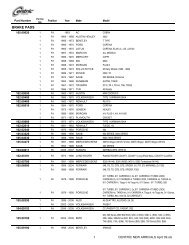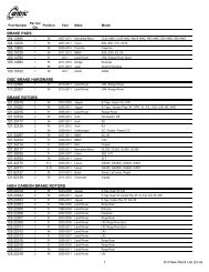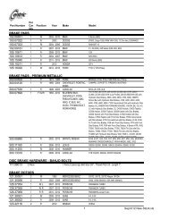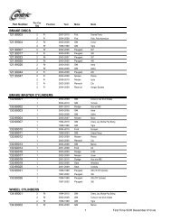
Brake Rotor Installation Tips - Centric Parts
Brake Rotor Installation Tips - Centric Parts
Brake Rotor Installation Tips - Centric Parts

You also want an ePaper? Increase the reach of your titles
YUMPU automatically turns print PDFs into web optimized ePapers that Google loves.
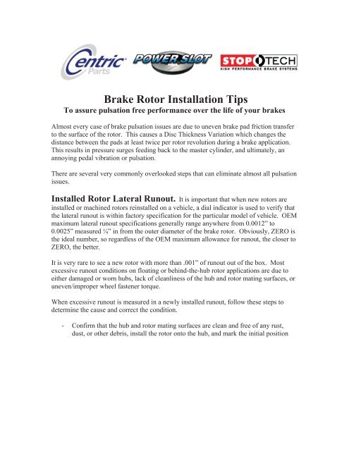
<strong>Brake</strong> <strong>Rotor</strong> <strong>Installation</strong> <strong>Tips</strong><br />
To assure pulsation free performance over the life of your brakes<br />
Almost every case of brake pulsation issues are due to uneven brake pad friction transfer<br />
to the surface of the rotor. This causes a Disc Thickness Variation which changes the<br />
distance between the pads at least twice per rotor revolution during a brake application.<br />
This results in pressure surges feeding back to the master cylinder, and ultimately, an<br />
annoying pedal vibration or pulsation.<br />
There are several very commonly overlooked steps that can eliminate almost all pulsation<br />
issues.<br />
Installed <strong>Rotor</strong> Lateral Runout. It is important that when new rotors are<br />
installed or machined rotors reinstalled on a vehicle, a dial indicator is used to verify that<br />
the lateral runout is within factory specification for the particular model of vehicle. OEM<br />
maximum lateral runout specifications generally range anywhere from 0.0012” to<br />
0.0025” measured ¼” in from the outer diameter of the brake rotor. Obviously, ZERO is<br />
the ideal number, so regardless of the OEM maximum allowance for runout, the closer to<br />
ZERO, the better.<br />
It is very rare to see a new rotor with more than .001” of runout out of the box. Most<br />
excessive runout conditions on floating or behind-the-hub rotor applications are due to<br />
either damaged or worn hubs, lack of cleanliness of the hub and rotor mating surfaces, or<br />
uneven/improper wheel fastener torque.<br />
When excessive runout is measured in a newly installed runout, follow these steps to<br />
determine the cause and correct the condition.<br />
- Confirm that the hub and rotor mating surfaces are clean and free of any rust,<br />
dust, or other debris, install the rotor onto the hub, and mark the initial position
with a paint mark on a lug stud and next to the corresponding lug hole.<br />
- Measure rotor runout, recording the ZERO location and the high spot location, as<br />
well the amount of runout on the surface of the rotor with a marker.<br />
- Next, remove the rotor and install in a different position on the hub:<br />
- Measure runout and record results once again. If the results from both<br />
measurements match in both location and amount of runout measured, then<br />
excessive runout exists in the rotor itself, and the rotor requires either replacement<br />
or machining.<br />
- If the results from both tests are marked in different locations on the rotor, then<br />
runout exists in the hub. If this is the case, cleanliness of mating surfaces should<br />
be confirmed once again, and then hub runout measured to confirm previous<br />
results. Any measurable hub runout requires hub replacement or a more short<br />
term solution of machining the disc on the hub using an on-car lathe. An on-car<br />
lathe with yield a finished product that compensates for any hub runout and if<br />
done correctly, will result in a rotor with ZERO installed runout when mounted to<br />
the hub in the same position in which it was machined. Any hub runout will show
up as a considerably higher number when measured at the edge of the rotor….the<br />
larger the rotor, the greater the increase in measured runout.<br />
- Minor runout conditions can sometimes be corrected by installing the rotor in<br />
different locations on the hub…if a minor runout condition exists in both the hub<br />
and the rotor, they can usually be “clocked” to counteract each other so that<br />
runout measured while the rotor is installed meets the factory specification.<br />
- Uneven wheel torque can distort and actually warp the rotor, creating runout.<br />
Make sure to use a torque wrench when installing lugs.<br />
- In more corrosive environments, even the most perfect brake job can go bad as<br />
rust develops between the hub and rotor over the course of the service life of the<br />
parts. Any rust development may “jack” the rotor away from the hub, creating<br />
runout. To resist situations like this, a high temperature grease or even paint can<br />
be applied to the mating surfaces before installation to act a sealer to delay<br />
corrosion.<br />
Uneven <strong>Brake</strong> Pad Friction Transfer:<br />
To function properly, modern brake pad formulas require a short bed-in to condition the<br />
brake rotor so that the system operates as designed. Conditioning the brake rotor or “bedin”<br />
consists of heat cycling the pads and rotor in a controlled manner to form a thin and<br />
uniform layer of brake pad friction material on the rotor surface. This is the “transfer<br />
layer”. When the brake pads are pressed against this layer of the same friction material<br />
on the rotor, bonds in the materials are broken and reformed converting the kinetic<br />
energy in the vehicle to heat energy to slow or stop the wheel.<br />
When a brake pad is operated outside of the temperature range for which it was designed,<br />
friction material transfer can become uncontrollable and occur in an uneven manner on<br />
the brake rotor. Additionally, since the transfer layer is constantly breaking down and<br />
renewing itself, runout in the rotor can cause the transfer to become uneven in thickness,<br />
causing a pedal pulsation. When a rotor has runout, there will be a relative “high spot”<br />
on each side of the rotor. These high spots will contact the pads at higher pressures than<br />
the rest of the rotor, and after the brakes are released, may contact the pads several times<br />
before the pads are able to retract while the pads are not contacting the “low spots”.<br />
These high spots will eventually develop a transfer layer that differs in thickness from the<br />
transfer layer on other parts of the rotor, making the high spots not only high, but also<br />
thicker than other parts of the rotor. This will cause a change in distance between the<br />
pads while the brakes are applied, resulting in a pedal pulsation.<br />
Additionally, if the brake pads are operating at the top of their designed temperature<br />
range or outside of their designed temperature range, and the driver comes to a complete<br />
stop and remains there with pedal pressure applied, excessive friction transfer can take<br />
place where the rotor came to rest between the pads, making it slightly thicker than the<br />
rest of the rotor and causing a pedal pulsation.