Chapter 21 Temperature Measurement of FBs-PLC and PID Control
Chapter 21 Temperature Measurement of FBs-PLC and PID Control
Chapter 21 Temperature Measurement of FBs-PLC and PID Control
Create successful ePaper yourself
Turn your PDF publications into a flip-book with our unique Google optimized e-Paper software.
FUN86<br />
TPCTL<br />
Convenient Instruction <strong>of</strong> <strong>PID</strong> <strong>Temperature</strong> <strong>Control</strong><br />
FUN86<br />
TPCTL<br />
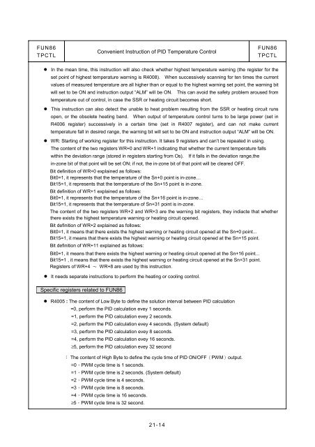
● In the mean time, this instruction will also check whether highest temperature warning (the register for the<br />
set point <strong>of</strong> highest temperature warning is R4008). When successively scanning for ten times the current<br />
values <strong>of</strong> measured temperature are all higher than or equal to the highest warning set point, the warning bit<br />
will set to be ON <strong>and</strong> instruction output “ALM” will be ON. This can avoid the safety problem aroused from<br />
temperature out <strong>of</strong> control, in case the SSR or heating circuit becomes short.<br />
● This instruction can also detect the unable to heat problem resulting from the SSR or heating circuit runs<br />
open, or the obsolete heating b<strong>and</strong>. When output <strong>of</strong> temperature control turns to be large power (set in<br />
R4006 register) successively in a certain time (set in R4007 register), <strong>and</strong> can not make current<br />
temperature fall in desired range, the warning bit will set to be ON <strong>and</strong> instruction output “ALM” will be ON.<br />
● WR: Starting <strong>of</strong> working register for this instruction. It takes 9 registers <strong>and</strong> can’t be repeated in using.<br />
The content <strong>of</strong> the two registers WR+0 <strong>and</strong> WR+1 indicating that whether the current temperature falls<br />
within the deviation range (stored in registers starting from Os). If it falls in the deviation range,the<br />
in-zone bit <strong>of</strong> that point will be set ON; if not, the in-zone bit <strong>of</strong> that point will be cleared OFF.<br />
Bit definition <strong>of</strong> WR+0 explained as follows:<br />
Bit0=1, it represents that the temperature <strong>of</strong> the Sn+0 point is in-zone…<br />
Bit15=1, it represents that the temperature <strong>of</strong> the Sn+15 point is in-zone.<br />
Bit definition <strong>of</strong> WR+1 explained as follows:<br />
Bit0=1, it represents that the temperature <strong>of</strong> the Sn+16 point is in-zone…<br />
Bit15=1, it represents that the temperature <strong>of</strong> Sn+31 point is in-zone.<br />
The content <strong>of</strong> the two registers WR+2 <strong>and</strong> WR+3 are the warning bit registers, they indiacte that whether<br />
there exists the highest temperature warning or heating circuit opened.<br />
Bit definition <strong>of</strong> WR+2 explained as follows:<br />
Bit0=1, it means that there exists the highest warning or heating circuit opened at the Sn+0 point...<br />
Bit15=1, it means that there exists the highest warning or heating circuit opened at the Sn+15 point.<br />
Bit definition <strong>of</strong> WR+11 explained as follows:<br />
Bit0=1, it means that there exists the highest warning or heating circuit opened at the Sn+16 point...<br />
Bit15=1 , it means that there exists the highest warning or heating circuit opened at the Sn+31 point.<br />
Registers <strong>of</strong> WR+4 ~ WR+8 are used by this instruction.<br />
● It needs separate instructions to perform the heating or cooling control.<br />
Specific registers related to FUN86<br />
● R4005 : The content <strong>of</strong> Low Byte to define the solution interval between <strong>PID</strong> calculation<br />
=0, perform the <strong>PID</strong> calculation evey 1 seconds.<br />
=1, perform the <strong>PID</strong> calculation evey 2 seconds.<br />
=2, perform the <strong>PID</strong> calculation evey 4 seconds. (System default)<br />
=3, perform the <strong>PID</strong> calculation evey 8 seconds.<br />
=4, perform the <strong>PID</strong> calculation evey 16 seconds.<br />
≥5, perform the <strong>PID</strong> calculation evey 32 second<br />
: The content <strong>of</strong> High Byte to define the cycle time <strong>of</strong> <strong>PID</strong> ON/OFF(PWM)output.<br />
=0,PWM cycle time is 1 seconds.<br />
=1,PWM cycle time is 2 seconds. (System default)<br />
=2,PWM cycle time is 4 seconds.<br />
=3,PWM cycle time is 8 seconds.<br />
=4,PWM cycle time is 16 seconds.<br />
≥5,PWM cycle time is 32 second.<br />
<strong>21</strong>-14


