Chapter 21 Temperature Measurement of FBs-PLC and PID Control
Chapter 21 Temperature Measurement of FBs-PLC and PID Control
Chapter 21 Temperature Measurement of FBs-PLC and PID Control

Create successful ePaper yourself
Turn your PDF publications into a flip-book with our unique Google optimized e-Paper software.
<strong>Chapter</strong> <strong>21</strong> <strong>Temperature</strong> <strong>Measurement</strong> <strong>of</strong> <strong>FBs</strong>-<strong>PLC</strong> <strong>and</strong> <strong>PID</strong> <strong>Control</strong><br />
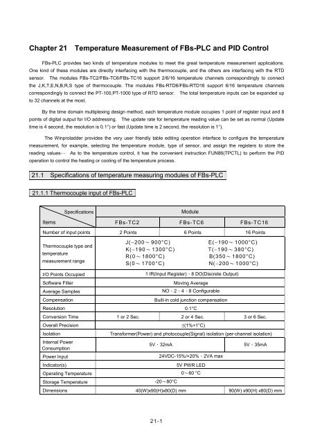
<strong>FBs</strong>-<strong>PLC</strong> provides two kinds <strong>of</strong> temperature modules to meet the great temperature measurement applications.<br />
One kind <strong>of</strong> these modules are directly interfacing with the thermocouple, <strong>and</strong> the others are interfacing with the RTD<br />
sensor. The modules <strong>FBs</strong>-TC2/<strong>FBs</strong>-TC6/<strong>FBs</strong>-TC16 support 2/6/16 temperature channels correspondingly to connect<br />
the J,K,T,E,N,B,R,S type <strong>of</strong> thermocouple. The modules <strong>FBs</strong>-RTD6/<strong>FBs</strong>-RTD16 support 6/16 temperature channels<br />
correspondingly to connect the PT-100,PT-1000 type <strong>of</strong> RTD sensor. The total temperature inputs can be exp<strong>and</strong>ed up<br />
to 32 channels at the most.<br />
By the time domain multiplexing design method, each temperature module occupies 1 point <strong>of</strong> register input <strong>and</strong> 8<br />
points <strong>of</strong> digital output for I/O addressing. The update rate for temperature reading value can be set as normal (Update<br />
time is 4 second, the resolution is 0.1°) or fast (Update time is 2 second, the resolution is 1°).<br />
The Winproladder provides the very user friendly table editing operation interface to configure the temperature<br />
measurement, for example, selecting the temperature module, type <strong>of</strong> sensor, <strong>and</strong> assign the registers to store the<br />
reading values… As to the temperature control, it has the convenient instruction FUN86(TPCTL) to perform the <strong>PID</strong><br />
operation to control the heating or cooling <strong>of</strong> the temperature process.<br />
<strong>21</strong>.1 Specifications <strong>of</strong> temperature measuring modules <strong>of</strong> <strong>FBs</strong>-<strong>PLC</strong><br />
<strong>21</strong>.1.1 Thermocouple input <strong>of</strong> <strong>FBs</strong>-<strong>PLC</strong><br />
Specifications<br />
Module<br />
Items <strong>FBs</strong>-TC2 <strong>FBs</strong>-TC6 <strong>FBs</strong>-TC16<br />
Number <strong>of</strong> input points 2 Points 6 Points 16 Points<br />
Thermocouple type <strong>and</strong><br />
temperature<br />
measurement range<br />
J(−200~ 900°C)<br />
K(−190~ 1300°C)<br />
R(0~ 1800°C)<br />
S(0~ 1700°C)<br />
E(−190~ 1000°C)<br />
T(−190~ 380°C)<br />
B(350~ 1800°C)<br />
N(−200~ 1000°C)<br />
I/O Points Occupied<br />
S<strong>of</strong>tware Filter<br />
Average Samples<br />
Compensation<br />
Resolution<br />
1 IR(Input Register)、8 DO(Discrete Output)<br />
Moving Average<br />
NO、2、4、8 Configurable<br />
Built-in cold junction compensation<br />
0.1°C<br />
Conversion Time 1 or 2 Sec. 2 or 4 Sec. 3 or 6 Sec.<br />
Overall Precision<br />
Isolation<br />
Internal Power<br />
Consumption<br />
Power Input<br />
Indicator(s)<br />
±(1%+1°C)<br />
Transformer(Power) <strong>and</strong> photocouple(Signal) isolation (per-channel isolation)<br />
5V,32mA<br />
24VDC-15%/+20%、2VA max<br />
5V PWR LED<br />
Operating <strong>Temperature</strong> 0~60 °C<br />
Storage <strong>Temperature</strong><br />
-20~80°C<br />
5V,35mA<br />
Dimensions 40(W)x90(H)x80(D) mm 90(W) x90(H) x80(D) mm<br />
<strong>21</strong>-1
<strong>21</strong>.1.2 RTD input <strong>of</strong> <strong>FBs</strong>-<strong>PLC</strong><br />
Specifications<br />
Module<br />
Items <strong>FBs</strong>-RTD6 <strong>FBs</strong>-RTD16<br />
Number <strong>of</strong> input points 6 Points 16 Points<br />
RTD type <strong>and</strong><br />
temperature<br />
measurement range<br />
I/O Points Occupied<br />
S<strong>of</strong>tware Filter<br />
Average Samples<br />
Resolution<br />
3-wire RTD sensor JIS(α=0.00392) or DIN(α=0.00385)<br />
Pt-100(−200~850°C)<br />
Pt-1000(−200~600°C)<br />
1 IR(Input Register)、8 DO(Discrete Output)<br />
Moving Average<br />
NO、2、4、8 Configurable<br />
0.1°C<br />
Conversion Time 1 or 2 Sec. 2 or 4 Sec.<br />
Overall Precision ±1%<br />
Isolation<br />
Internal Power<br />
Consumption<br />
Power Input<br />
Transformer(Power) <strong>and</strong> photocouple(Signal) isolation (per-channel isolation)<br />
5V,35mA<br />
5V,35mA<br />
24VDC-15%/+20%、2VA max<br />
Indicator(s)<br />
5V PWR LED<br />
Operating <strong>Temperature</strong> 0~60 °C<br />
Storage <strong>Temperature</strong><br />
-20~80°C<br />
Dimensions 40(W)x90(H)x80(D) mm 90(W) x90(H) x80(D)mm<br />
<strong>21</strong>.2 The procedure <strong>of</strong> using <strong>FBs</strong> temperature module<br />
<strong>21</strong>.2.1 <strong>Temperature</strong> measurement procedure<br />
Start<br />
Connect Modules to the expansion interface on <strong>PLC</strong> in<br />
series <strong>and</strong> connect an external 24VDC source <strong>and</strong><br />
temperature measure input wires.<br />
------- Please refer to section <strong>21</strong>.6 for setting <strong>and</strong> wiring.<br />
Executing the WinProladder <strong>and</strong> configure the<br />
configuration table address、<strong>Temperature</strong> register<br />
address <strong>and</strong> working register in “Temp. configuration”<br />
windows then you can read temperature value from<br />
register directly.<br />
------- Please refer to section <strong>21</strong>.3<br />
End<br />
<strong>21</strong>-2
<strong>21</strong>.2.2 Closed loop <strong>PID</strong> temperature control<br />
Start<br />
Connect Modules to the expansion interface on <strong>PLC</strong> in<br />
<strong>21</strong>-3
1.〔Starting Address <strong>of</strong> Configuration Table〕: Assign the starting <strong>of</strong> registers to store the temperature configuration table,<br />
there will allow the following inputs.<br />
a. Space (Without temperature configuration table)<br />
b. Rxxxx or Dxxxxx<br />
The configuration table will occupy 4+N <strong>of</strong> registers, where N is the number <strong>of</strong> modules.<br />
As shown the sample above, R5000~R5005 stores the table<br />
2.〔.Starting Address <strong>of</strong> Temp. Register〕: Assign the starting <strong>of</strong> registers to store the current temperature reading<br />
values, there will allow the following inputs, Rxxxx or Dxxxxx ; 1 channel <strong>of</strong> temperature occupies 1 register as<br />
shown the sample above, R0~R31 stores the reading values. The resolution <strong>of</strong> reading value is 0.1°.<br />
For example. R0=1234, it means 123.4°<br />
3.〔Starting Address <strong>of</strong> Working Register〕: Assign the starting <strong>of</strong> registers to reserve the working registers, there will<br />
allow the following inputs Rxxxx or Dxxxxx<br />
As shown the sample above, D0~D11 are the working registers<br />
【<strong>Temperature</strong> module installation information <strong>and</strong> setup】<br />
4.〔Module #1 ~ # 8〕: Display the name <strong>of</strong> the installed temperature module <strong>and</strong> the analog starting address <strong>of</strong> it's own,<br />
there are the following modules。<br />
○1 TC6 (6 channels <strong>of</strong> thermocouple input)<br />
○2 RTD6 (6 channels <strong>of</strong> RTD input)<br />
○3 TC16 (16 channels <strong>of</strong> thermocouple input)<br />
○4 RTD16 (16 channels <strong>of</strong> RTD input)<br />
○5 TC2 (2 channels <strong>of</strong> thermocouple input)<br />
※The Sensor Type field is used to assign <strong>and</strong> display the sensor type, the detail Sensor Type please refer to section <strong>21</strong>.1<br />
5.〔Unit <strong>of</strong> <strong>Temperature</strong>〕: Assign the unit <strong>of</strong> temperature, there have the following selections<br />
○1 Celsius<br />
○2 Fahrenheit<br />
6.〔Times <strong>of</strong> Average〕: Assign the times <strong>of</strong> average for temperature measurement, there have the following selections,<br />
No / 2 / 4 / 8.<br />
7.〔Scan Rate〕: Assign the update rate <strong>of</strong> temperature reading value, there will have the following selections : Normal<br />
(Update time is 4 second, the measurement resolution is 0.1°), Fast (Update time is 2 second, the<br />
measurement resolution is 1°). The resolution <strong>of</strong> reading value is always 0.1°.<br />
<strong>21</strong>.3.1 The internal format <strong>of</strong> temperature configuration table<br />
This introduction is for trouble shooting or HMI or SCADA User, because they may modify through registers.<br />
Winprolader’s User can ignore this introduction. When you configure temperature configuration table with Winproladder,<br />
these value <strong>of</strong> registers will be finished. When SR+0 = A556h, it means valid temperature configuration table. But if SR+0<br />
= other values, it means invalid temperature configuration table.<br />
<strong>21</strong>-4
Address High Byte Low Byte<br />
SR + 0 A5H 56H<br />
SR + 1 Quantity <strong>of</strong> temperature modules (1~8)<br />
SR + 2<br />
SR + 3<br />
Starting address <strong>of</strong> reading values<br />
Starting address <strong>of</strong> working registers<br />
SR + 4 Type <strong>of</strong> sensor (#1) Module name (#1)<br />
SR + 5 Type <strong>of</strong> sensor (#2) Module name (#2)<br />
SR + 6 Type <strong>of</strong> sensor (#3) Module name (#3)<br />
SR + 7 Type <strong>of</strong> sensor (#4) Module name (#4)<br />
SR + 8 Type <strong>of</strong> sensor (#5) Module name (#5)<br />
SR + 9 Type <strong>of</strong> sensor (#6) Module name (#6)<br />
.<br />
.<br />
.<br />
.<br />
.<br />
.<br />
.<br />
.<br />
.<br />
※ The temperature configuration table occupies (4+N) registers in total ; where N is the quantity <strong>of</strong> modules.<br />
<strong>21</strong>.3.2 The internal format <strong>of</strong> working registers<br />
Supposing the starting address is WR<br />
Address High Byte Low Byte<br />
WR+0 Execute Code XXXXH<br />
WR+1 Sensor abnormal indicator (Sensor 0 ~ Sensor 15)<br />
WR+2 Sensor abnormal indicator (Sensor 16 ~ Sensor 31)<br />
WR+3 Total amount <strong>of</strong> TP channel Qty <strong>of</strong> <strong>Temperature</strong> Module<br />
WR+4 Type <strong>of</strong> sensor <strong>of</strong> Module #1 D.O. <strong>of</strong> TP Module #1<br />
WR+5 Channel No. <strong>of</strong> Module #1 A.I. <strong>of</strong> TP Module #1<br />
WR+6 Reading start <strong>of</strong> <strong>Temperature</strong> Module #1<br />
WR+7 Current channel <strong>of</strong> <strong>Temperature</strong> Module #1<br />
.<br />
.<br />
.<br />
.<br />
.<br />
.<br />
WR+(N×4)+0 Sensor <strong>of</strong> Module #N D.O. <strong>of</strong> TP Module #N<br />
WR+(N×4)+1 Channel No. <strong>of</strong> Module #N A.I. <strong>of</strong> TP Module #N<br />
WR+(N×4)+2 Reading start <strong>of</strong> <strong>Temperature</strong> Module #N<br />
WR+(N×4)+3 Current channel <strong>of</strong> <strong>Temperature</strong> Module #N<br />
Notes :<br />
1. Lower byte <strong>of</strong> WR+0 : Tells the mismatch between the configuration table & installed temperature board<br />
b0=1,means module #1<br />
.<br />
.<br />
.<br />
b7=1,means module #8<br />
<strong>21</strong>-5
2. Upper byte <strong>of</strong> WR+0 : Execute Code<br />
= 00H,Idle<br />
= FFH,TP channel > 32, w/o temperature measurement<br />
= FEH,lower byte <strong>of</strong> WR+3 = 0 or > 8, same as above<br />
= 56H,already read all TP channels, measurement in progress<br />
※ The working table occupies (N×4)+4 registers in total ; where N is the quantity <strong>of</strong> modules<br />
<strong>21</strong>.3.3 Description <strong>of</strong> related special registers for temperature measurement<br />
sensor's installation status<br />
• R4010 : Each bit <strong>of</strong> R4010 to tell the status <strong>of</strong> the sensor's installation.<br />
Bit0=1 means that 1 st point <strong>of</strong> temperature sensor is installed.<br />
Bit1=1 means that 2 nd point <strong>of</strong> temperature sensor is installed.<br />
‧<br />
‧<br />
Bit15=1 means that 16 th point <strong>of</strong> temperature sensor is installed.<br />
(The default <strong>of</strong> R4010 is FFFFH)<br />
• R4011 : Each bit <strong>of</strong> R4011 to tell the status <strong>of</strong> the sensor's installation.<br />
Bit0=1 means that 17 th point <strong>of</strong> temperature sensor is installed.<br />
Bit1=1 means that 18 th point <strong>of</strong> temperature sensor is installed.<br />
‧<br />
‧<br />
Bit15=1 means that 32 th point <strong>of</strong> temperature sensor is installed.<br />
(The default <strong>of</strong> R4011 is FFFFH)<br />
• When the temperature sensor is installed (the corresponding bit <strong>of</strong> R4010 or R4011 must be 1), the system<br />
will perform the line broken detection to the sensor. If there is line broken happened to the sensor, there<br />
will have the warning <strong>and</strong> the line broken value will be displayed.<br />
• When the temperature sensor is not installed (the corresponding bit <strong>of</strong> R4010 or R4011 must be 0), the<br />
system won’t perform the line broken detection to the sensor <strong>and</strong> there will not have the warning; the<br />
temperature value will be displayed as 0.<br />
• Depends on the sensor's installation, the ladder program may control the corresponding bit <strong>of</strong> R4010 <strong>and</strong><br />
R4011 to perform or not to perform the line broken detection.<br />
<strong>21</strong>.4 I/O addressing <strong>of</strong> temperature module<br />
By the time domain multiplexing design method, each temperature module occupies 1 point <strong>of</strong> input register <strong>and</strong> 8<br />
points <strong>of</strong> digital output for I/O addressing. For correct I/O access, the I/O addressing <strong>of</strong> expension modules following the<br />
temperature module must be added the I/O quantity which the corresponding module shoud have. The WinProladder<br />
provides the easy <strong>and</strong> convenient way to calculate the I/O address for the expension modules through the on-line "I/O<br />
Numbering" operation.<br />
<strong>21</strong>.5 <strong>Temperature</strong> modules hardware description<br />
<strong>Temperature</strong> modules contains 3 PCBs overlapping one another. The lowest one is the power supply unit (isolated<br />
power supply). The middle one is the I/O board (connectors are on this layer). The upper one is the control board<br />
(control/expansion I/O connections) as described below.:<br />
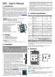
<strong>21</strong>.5.1 <strong>FBs</strong>-TC2、TC6、TC16 outlook <strong>of</strong> top view<br />
<strong>21</strong>-6
TC2<br />
1 6 7 8<br />
2<br />
T0+<br />
T0-<br />
T1+<br />
T1-<br />
FATEK<br />
4<br />
POW<br />
3<br />
5<br />
TC6<br />
1 6 7 8<br />
2<br />
T2+<br />
T4+<br />
T2- T3+ T3- T4- T5+<br />
T5-<br />
T0+<br />
T0- T1+<br />
T1-<br />
FATEK<br />
4<br />
POW<br />
3<br />
5<br />
9<br />
10<br />
11<br />
12<br />
<strong>21</strong>-7
TC16<br />
1 6 7 8 9 10 11 12<br />
2<br />
T0+ T1+ T2+<br />
T0- T1- T2- T3+ T4+ T5+ T6+<br />
T3- T4- T5- T6-<br />
PROGRAMMABLE<br />
CONTROLLER<br />
POW<br />
4<br />
3<br />
T7+<br />
T7- T8+ T9+ T10+ T11+ T12+ T13+ T14+ T15+<br />
T8- T9- T10- T11- T12- T13- T14- T15-<br />
5<br />
13 14<br />
15 16 17 18 19 20 <strong>21</strong><br />
○1 External power input terminal : Power supply for analogue circuit <strong>of</strong> <strong>FBs</strong>-TCXX module, supply voltage is<br />
24VDC±20%<br />
○2 Protecting ground terminal:Connect to the shielding <strong>of</strong> signal cable.<br />
○3 Expansion input cable:It should be connected to the front expansion unit, or the expansion output <strong>of</strong> main unit.<br />
○4 Expansion output connector:Provides the connection for next expansion unit.<br />
○5 Power indicator: Indicates whether the power supply at analogue circuit <strong>and</strong> external input power source are normal.<br />
○6 Input terminal for 1 st<br />
○7 Input terminal for 2 nd<br />
TC input:The TC input <strong>of</strong> channel0(T0+、T0-)<br />
TC input:The TC input <strong>of</strong> channel1(T1+、T1-)<br />
○8 ~○<strong>21</strong> Input terminal for (3 rd ~16 th ) TC input: The TC input <strong>of</strong> channel2~channel15(T2+、T2-~T15+、T15-)<br />
<strong>21</strong>-8
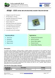
<strong>21</strong>.5.2 <strong>FBs</strong>-RTD6、RTD16 outlook <strong>of</strong> top view<br />
RTD6<br />
1 6 7 8<br />
2<br />
P0+ P1+<br />
COM P0- P1-<br />
FATEK<br />
4<br />
POW<br />
3<br />
P2+ P3+<br />
P2- P3- P4+ P5+<br />
P4- P5-<br />
5<br />
9 10 11 12<br />
RTD16<br />
1<br />
6<br />
7<br />
8<br />
9<br />
10 11<br />
12<br />
13<br />
2<br />
P0+<br />
COM<br />
P1+<br />
P0-<br />
P2+ P3+ P4+ P5+ P6+<br />
P1- P2- P3- P4- P5- P6-<br />
PROGRAMMABLE<br />
CONTROLLER<br />
POW<br />
4<br />
3<br />
P7+<br />
P8-<br />
P10+ P11+ P12+ P13+ P14+ P15+<br />
P9- P10- P11- P12- P13- P14- P15- 5<br />
14<br />
P7- P8+ P9+ 17 18<br />
15 16<br />
19<br />
20 <strong>21</strong><br />
22<br />
<strong>21</strong>-9
○1 External power input terminal : Power supply for analogue circuit <strong>of</strong> <strong>FBs</strong>-RTDXX module, supply voltage is<br />
24VDC±20%<br />
○2 Protecting ground terminal:Connect to the shielding signal cable.<br />
○3 Expansion input cable:It should be connected to the front expansion unit, or the expansion output <strong>of</strong> main unit.<br />
○4 Expansion output connector:Provides the connection for next expansion unit.<br />
○5 Power indicator: Indicates whether the power supply at analogue circuit <strong>and</strong> external input power source are normal.<br />
○6 Common terminal for 3-wires RTD input: To connect to the common wire <strong>of</strong> each 3-wires RTD input.<br />
○7 Input terminal for 1 st<br />
RTD input: The RTD input <strong>of</strong> channel0(P0+、P0-)<br />
○8 ~○22 Input terminal for (2 nd ~16 th ) RTD input: The RTD input <strong>of</strong> channel1~15 (P1+、P1-~P15+、P15-)<br />
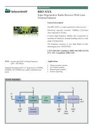
<strong>21</strong>.6 Wiring <strong>of</strong> the temperature modules<br />
<strong>21</strong>.6.1 Wiring <strong>of</strong> the thermocouple input module<br />
<strong>FBs</strong>-TC××<br />
Inputs<br />
24V+ + 24VDC<br />
24V<br />
External power supply<br />
+<br />
TC0+<br />
TC0<br />
J(K) extension cable<br />
+<br />
J(K) type<br />
thermocouple<br />
thermocouple<br />
+<br />
TC1+<br />
TC1<br />
+<br />
J(K) type<br />
thermocouple<br />
thermocouple<br />
Thermocouple<br />
Input<br />
+<br />
TCn+<br />
TCn<br />
+<br />
J(K) type<br />
thermocouple<br />
thermocouple<br />
Multiplexer<br />
extension J(K) extension cable cable<br />
(Shielding must be connected to FG)<br />
If it's <strong>FBs</strong>-TC6, n is 5<br />
If it's <strong>FBs</strong>-TC16, n is 15<br />
<strong>21</strong>-10
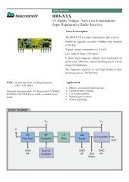
<strong>21</strong>.6.2 Wiring <strong>of</strong> the RTD input module<br />
<strong>FBs</strong>-RTD<br />
××<br />
Inputs<br />
24V+ +<br />
24V<br />
24VDC<br />
External power supply<br />
+<br />
P0+<br />
P0<br />
Red line<br />
White line<br />
RTD Sensor<br />
COM<br />
White line<br />
+<br />
+<br />
P1+<br />
P1<br />
Red line<br />
White line<br />
White line<br />
RTD Sensor<br />
+<br />
Pn+<br />
Red line<br />
Multiplexer<br />
Pn<br />
White line<br />
White line<br />
RTD Sensor<br />
If it's <strong>FBs</strong>-RTD6, n is 5<br />
If it's <strong>FBs</strong>-RTD16, n is 15<br />
<strong>21</strong>.7 Instructions explanation <strong>and</strong> program example for temperature measurement <strong>and</strong><br />
<strong>PID</strong> temperature control <strong>of</strong> <strong>FBs</strong>-<strong>PLC</strong><br />
The followings are the instructions explanation <strong>and</strong> program example for temperature measurement <strong>and</strong> <strong>PID</strong><br />
temperature control <strong>of</strong> <strong>FBs</strong>-<strong>PLC</strong>.<br />
<strong>21</strong>-11
FUN86<br />
TPCTL<br />
Convenient Instruction <strong>of</strong> <strong>PID</strong> <strong>Temperature</strong> <strong>Control</strong><br />
FUN86<br />
TPCTL<br />
Oper<strong>and</strong><br />
Md<br />
Yn<br />
Sn<br />
Zn<br />
Range<br />
Y HR ROR DR K<br />
Y0<br />
∣<br />
Y255<br />
○<br />
R0<br />
∣<br />
R3839<br />
R5000<br />
∣<br />
R8071<br />
D0<br />
∣<br />
D3999<br />
Sv ○ ○* ○<br />
Os ○ ○* ○<br />
PR ○ ○* ○<br />
IR ○ ○* ○<br />
DR ○ ○* ○<br />
OR ○ ○* ○<br />
WR ○ ○* ○<br />
0~1<br />
0~31<br />
1~32<br />
Md : Selection <strong>of</strong> <strong>PID</strong> method<br />
=0, Modified minimum overshoot method<br />
=1, Universal <strong>PID</strong> method<br />
Yn : Starting address <strong>of</strong> <strong>PID</strong> ON/OFF output;<br />
it takes Zn points.<br />
Sn : Starting point <strong>of</strong> <strong>PID</strong> control <strong>of</strong> this instruction;<br />
Sn = 0~31.<br />
Zn : Number <strong>of</strong> the <strong>PID</strong> control <strong>of</strong> this instruction;<br />
1≤ Zn ≤32 <strong>and</strong> 1 ≤ Sn+Zn ≤ 32<br />
Sv : Starting register <strong>of</strong> the setpoint;<br />
it takes Zn registers. (Unit in 0.1°)<br />
Os : Starting register <strong>of</strong> the in-zone <strong>of</strong>fset;<br />
it takes Zn registers. (Unit in 0.1°)<br />
PR : Starting register <strong>of</strong> the gain (Kc);<br />
it takes Zn registers.<br />
IR :Starting register <strong>of</strong> integral tuning constant (Ki);it<br />
takes Zn registers.<br />
DR : Starting register <strong>of</strong> derivative tuning constant<br />
(Td); it takes Zn registers.<br />
OR : Starting register <strong>of</strong> the <strong>PID</strong> analog output;<br />
it takes Zn registers.<br />
WR: Starting <strong>of</strong> working register for this instruction.<br />
It takes 9 registers <strong>and</strong> can’t be repeated in<br />
using.<br />
● By employing the temperature module <strong>and</strong> table editing method to get the current value <strong>of</strong> temperature <strong>and</strong> let<br />
it be as so called Process Variable (PV); after the calculation <strong>of</strong> s<strong>of</strong>tware <strong>PID</strong> expression, it will respond the<br />
error with an output signal according to the setting <strong>of</strong> Set Point (SP),the error's integral <strong>and</strong> the rate <strong>of</strong> change<br />
<strong>of</strong> the process variable. Through the closed loop operation, the steady state <strong>of</strong> the process may be expected.<br />
● Convert the output <strong>of</strong> <strong>PID</strong> calculation to be the time proportional on/<strong>of</strong>f (PWM) output, <strong>and</strong> via transistor output<br />
to control the SSR for heating or cooling process; this is a good performance <strong>and</strong> very low cost solution.<br />
● Through the analog output module (D/A module), the output <strong>of</strong> <strong>PID</strong> calculation may control the SCR or<br />
proportional valve to get more precise process control.<br />
● Digitized <strong>PID</strong> expression is as follows:<br />
n<br />
M n =[Kc × E n ]+∑ [K c × K i × T s × E n ]+[K c × T d × (PV n − PV n-1 )/T s ]<br />
0<br />
M n : Output at time “n”.<br />
K c : Gain (Range: 1~9999;Pb=1000 / Kc ×0.1%, Unit in 0.1%)<br />
K i : Integral tuning constant (Range:0~9999, equivalent to 0.00~99.99 Repeat/Minute)<br />
T d : Derivative tuning constant (Range:0~9999, equivalent to 0.00~99.99 Minute)<br />
PVn : Process variable at time “n”<br />
PVn − 1 : Process variable when loop was last sovled<br />
E n : Error at time “n” ; E= SP – PVn<br />
T s : Solution interval for <strong>PID</strong> calculation (Valid value are 10, 20, 40, 80,160, 320; the unit is in 0.1Sec)<br />
<strong>21</strong>-12
FUN86<br />
TPCTL<br />
Convenient Instruction <strong>of</strong> <strong>PID</strong> <strong>Temperature</strong> <strong>Control</strong><br />
FUN86<br />
TPCTL<br />
Principle <strong>of</strong> <strong>PID</strong> parameter adjustment<br />
● As the gain (Kc) adjustment getting larger, the larger the proportional contribution to the output. This can<br />
obtain a sensitive <strong>and</strong> rapid control reaction. However, when the gain is too large, it may cause oscillation.<br />
Do the best to adjust “Kc” larger (but not to the extent <strong>of</strong> making oscillation), which could increase the<br />
process reaction <strong>and</strong> reduce the steady state error.<br />
● Integral item may be used to eliminate the steady state error. The larger the number ( Ki, integral tuning<br />
constant, Ki=1/Ti ), the larger the integral contribution to the output. When there is steady state error, adjust<br />
the “Ki” larger to decrease the error.<br />
When the “Ki” = 0, the integral item makes no contribution to the output.<br />
For example : if the reset time is 5 minutes, Ki=1/Ti=100/5=20;It means integral tuning constant is 0.2 Repeat/Minute<br />
● Derivative item may be used to make the process smoother <strong>and</strong> not too over shoot. The larger the number<br />
(Td, derivative tuning constant), the larger the derivative contribution to the output. When there is too over<br />
shoot, adjust the “Td” larger to decrease the amount <strong>of</strong> over shoot.<br />
When the “Td” = 0, the derivative item makes no contribution to the output.<br />
For example : if the rate time is 1 minute, then the Td = 100; if the differential time is 2 minute, then the Td = 200.<br />
● Properly adjust the <strong>PID</strong> parameters can obtain an excellent result for temperature control.<br />
● The default solution interval for <strong>PID</strong> calculation is 4 seconds (Ts=40).<br />
● The default <strong>of</strong> gain value (Kc) is 110, where Pb=1000/110×0.1%≒0.91%; the system full range is 1638°, it<br />
means the value SP-14.8° (1638×0.91≒14.8) will let <strong>PID</strong> operation enter proportional b<strong>and</strong> control.<br />
● The default <strong>of</strong> integral tuning constant is 17<br />
● The default <strong>of</strong> derivative tuning constant is50, it means the rate time is 0.5 minutes (Td=50).<br />
● When changing the <strong>PID</strong> solution interval, it may tune the parameters Kc, Ki, Td again.<br />
Instruction guide<br />
● FUN86 will be enabled after reading all temperature channels.<br />
● When execution control “EN” = 1, it depends on the input status <strong>of</strong> H/C for <strong>PID</strong> operation to make heating<br />
(H/C=1) or cooling (H/C=0) control. The current values <strong>of</strong> measured temperature are through the<br />
multiplexing temperature module ; the set points <strong>of</strong> desired temperature are stored in the registers starting<br />
from Sv. With the calculation <strong>of</strong> s<strong>of</strong>tware <strong>PID</strong> expression, it will respond the error with an output signal<br />
according to the setting <strong>of</strong> set point, the error's integral <strong>and</strong> the rate <strong>of</strong> change <strong>of</strong> the process variable.<br />
Convert the output <strong>of</strong> <strong>PID</strong> calculation to be the time proportional on/<strong>of</strong>f (PWM) output, <strong>and</strong> via transistor<br />
output to control the SSR for heating or cooling process; where there is a good performance <strong>and</strong> very low<br />
cost solution. It may also apply the output <strong>of</strong> <strong>PID</strong> calculation (stored in registers starting from OR), by way<br />
<strong>of</strong> D/A analog output module, to control SCR or proportional valve, so as to get more precise process control.<br />
● When the setting <strong>of</strong> Sn, Zn (0 Sn 31 <strong>and</strong> 1 Zn 32, as well as 1 Sn + Zn 32) comes error, this<br />
instruction will not be executed <strong>and</strong> the instruction output “ERR” will be ON.<br />
● This instruction compares the current value with the set point to check whether the current temperature falls<br />
within deviation range (stored in register starting from Os). If it falls in the deviation range, it will set the<br />
in-zone bit <strong>of</strong> that point to be ON; if not, clear the in-zone bit <strong>of</strong> that point to be OFF, <strong>and</strong> make instruction<br />
output “ALM” to be ON.<br />
<strong>21</strong>-13
FUN86<br />
TPCTL<br />
Convenient Instruction <strong>of</strong> <strong>PID</strong> <strong>Temperature</strong> <strong>Control</strong><br />
FUN86<br />
TPCTL<br />
● In the mean time, this instruction will also check whether highest temperature warning (the register for the<br />
set point <strong>of</strong> highest temperature warning is R4008). When successively scanning for ten times the current<br />
values <strong>of</strong> measured temperature are all higher than or equal to the highest warning set point, the warning bit<br />
will set to be ON <strong>and</strong> instruction output “ALM” will be ON. This can avoid the safety problem aroused from<br />
temperature out <strong>of</strong> control, in case the SSR or heating circuit becomes short.<br />
● This instruction can also detect the unable to heat problem resulting from the SSR or heating circuit runs<br />
open, or the obsolete heating b<strong>and</strong>. When output <strong>of</strong> temperature control turns to be large power (set in<br />
R4006 register) successively in a certain time (set in R4007 register), <strong>and</strong> can not make current<br />
temperature fall in desired range, the warning bit will set to be ON <strong>and</strong> instruction output “ALM” will be ON.<br />
● WR: Starting <strong>of</strong> working register for this instruction. It takes 9 registers <strong>and</strong> can’t be repeated in using.<br />
The content <strong>of</strong> the two registers WR+0 <strong>and</strong> WR+1 indicating that whether the current temperature falls<br />
within the deviation range (stored in registers starting from Os). If it falls in the deviation range,the<br />
in-zone bit <strong>of</strong> that point will be set ON; if not, the in-zone bit <strong>of</strong> that point will be cleared OFF.<br />
Bit definition <strong>of</strong> WR+0 explained as follows:<br />
Bit0=1, it represents that the temperature <strong>of</strong> the Sn+0 point is in-zone…<br />
Bit15=1, it represents that the temperature <strong>of</strong> the Sn+15 point is in-zone.<br />
Bit definition <strong>of</strong> WR+1 explained as follows:<br />
Bit0=1, it represents that the temperature <strong>of</strong> the Sn+16 point is in-zone…<br />
Bit15=1, it represents that the temperature <strong>of</strong> Sn+31 point is in-zone.<br />
The content <strong>of</strong> the two registers WR+2 <strong>and</strong> WR+3 are the warning bit registers, they indiacte that whether<br />
there exists the highest temperature warning or heating circuit opened.<br />
Bit definition <strong>of</strong> WR+2 explained as follows:<br />
Bit0=1, it means that there exists the highest warning or heating circuit opened at the Sn+0 point...<br />
Bit15=1, it means that there exists the highest warning or heating circuit opened at the Sn+15 point.<br />
Bit definition <strong>of</strong> WR+11 explained as follows:<br />
Bit0=1, it means that there exists the highest warning or heating circuit opened at the Sn+16 point...<br />
Bit15=1 , it means that there exists the highest warning or heating circuit opened at the Sn+31 point.<br />
Registers <strong>of</strong> WR+4 ~ WR+8 are used by this instruction.<br />
● It needs separate instructions to perform the heating or cooling control.<br />
Specific registers related to FUN86<br />
● R4005 : The content <strong>of</strong> Low Byte to define the solution interval between <strong>PID</strong> calculation<br />
=0, perform the <strong>PID</strong> calculation evey 1 seconds.<br />
=1, perform the <strong>PID</strong> calculation evey 2 seconds.<br />
=2, perform the <strong>PID</strong> calculation evey 4 seconds. (System default)<br />
=3, perform the <strong>PID</strong> calculation evey 8 seconds.<br />
=4, perform the <strong>PID</strong> calculation evey 16 seconds.<br />
≥5, perform the <strong>PID</strong> calculation evey 32 second<br />
: The content <strong>of</strong> High Byte to define the cycle time <strong>of</strong> <strong>PID</strong> ON/OFF(PWM)output.<br />
=0,PWM cycle time is 1 seconds.<br />
=1,PWM cycle time is 2 seconds. (System default)<br />
=2,PWM cycle time is 4 seconds.<br />
=3,PWM cycle time is 8 seconds.<br />
=4,PWM cycle time is 16 seconds.<br />
≥5,PWM cycle time is 32 second.<br />
<strong>21</strong>-14
FUN86<br />
TPCTL<br />
Convenient Instruction <strong>of</strong> <strong>PID</strong> <strong>Temperature</strong> <strong>Control</strong><br />
FUN86<br />
TPCTL<br />
Note 1 : When changing the value <strong>of</strong> R4005, the execution control “EN” <strong>of</strong> FUN86 must be set at 0. The next time<br />
when execution control “EN” =1, it will base on the latest set point to perform the <strong>PID</strong> calculation.<br />
Note 2 : The smaller the cycle time <strong>of</strong> PWM, the more even can it perform the heating. However, the error<br />
caused by the <strong>PLC</strong> scan time will also become greater. For the best control, it can base on the scan time<br />
<strong>of</strong> <strong>PLC</strong> to adjust the solution interval <strong>of</strong> <strong>PID</strong> calculation <strong>and</strong> the PWM cycle time.<br />
● R4006:The setting point <strong>of</strong> large power output detection for SSR or heating circuit opened, or heating b<strong>and</strong><br />
obsolete. The unit is in % <strong>and</strong> the setting range falls in 80~100(%); system default is 90(%).<br />
● R4007:The setting time to detect the continuing duration <strong>of</strong> large power output while SSR or heating circuit<br />
opened, or heating b<strong>and</strong> obsolete. The unit is in second <strong>and</strong> the setting range falls in 60~65535<br />
(seconds); system default is 600 (seconds).<br />
● R4008:The setting point <strong>of</strong> highest temperature warning for SSR, or heating circuit short detection. The unit<br />
is in 0.1 degree <strong>and</strong> the setting range falls in 100~65535; system default is 3500 (Unit in 0.1°).<br />
● R4012:Each bit <strong>of</strong> R4012 to tell the need <strong>of</strong> <strong>PID</strong> temperature control.<br />
Bit0=1 means that 1 st point needs <strong>PID</strong> temperature control.<br />
Bit1=1 means that 2 nd point needs <strong>PID</strong> temperature control.<br />
‧<br />
‧<br />
Bit15=1 means that 16 th point needs <strong>PID</strong> temperature control.<br />
(The default <strong>of</strong> R4012 is FFFFH)<br />
● R4013:Each bit <strong>of</strong> R4013 to tell the need <strong>of</strong> <strong>PID</strong> temperature control.<br />
Bit0=1 means that 17 th point needs <strong>PID</strong> temperature control.<br />
Bit1=1 means that 18 th point needs <strong>PID</strong> temperature control.<br />
‧<br />
‧<br />
Bit15=1 means that 32 th point needs <strong>PID</strong> temperature control.<br />
(The default <strong>of</strong> R4013 is FFFFH)<br />
●<br />
●<br />
●<br />
While execution control “EN”=1 <strong>and</strong> the corresponding bit <strong>of</strong> <strong>PID</strong> control <strong>of</strong> that point is ON (corresponding<br />
bit <strong>of</strong> R4012 or R4013 must be 1), the FUN86 instruction will perform the <strong>PID</strong> operation <strong>and</strong> respond to the<br />
calculation with the output signal.<br />
While execution control “EN”=1 <strong>and</strong> the corresponding bit <strong>of</strong> <strong>PID</strong> control <strong>of</strong> that point is OFF<br />
(corresponding bit <strong>of</strong> R4012 or R4013 must be 0), the FUN86 will not perform the <strong>PID</strong> operation <strong>and</strong> the<br />
output <strong>of</strong> that point will be OFF.<br />
The ladder program may control the corresponding bit <strong>of</strong> R4012 <strong>and</strong> R4013 to tell the FUN86 to perform or<br />
not to perform the <strong>PID</strong> control, <strong>and</strong> it needs only one FUN86 instruction.<br />
<strong>21</strong>-15
FUN86<br />
TPCTL<br />
Convenient Instruction <strong>of</strong> <strong>PID</strong> <strong>Temperature</strong> <strong>Control</strong><br />
FUN86<br />
TPCTL<br />
Program example<br />
08.MOV<br />
EN<br />
S<br />
: WM800<br />
D<br />
: R4012<br />
M0<br />
EN<br />
86.TPCTL<br />
MD : 0<br />
ERR<br />
M100<br />
H/C<br />
Yn<br />
Sn<br />
: Y30<br />
: 0<br />
ALM<br />
M101<br />
Zn<br />
: 10<br />
Sv<br />
: R100<br />
Os<br />
: R110<br />
PR<br />
: R120<br />
IR<br />
: R130<br />
DR<br />
: R140<br />
OR<br />
: R200<br />
WR : R300<br />
08.MOV<br />
EN<br />
S<br />
: R300<br />
D : WM400<br />
08.MOV<br />
EN<br />
S<br />
: R302<br />
D : WM416<br />
Description<br />
● The status <strong>of</strong> M800~M815 are controlled by the MMI or external inputs to tell which temperature channel<br />
needs <strong>PID</strong> control; if the corresponding bit is ON, it means yes; if the bit is OFF, it means no <strong>PID</strong> control.<br />
● When M0=ON, it will perform the <strong>PID</strong> heating control <strong>of</strong> 10 (Zn=10) channels from channel 0 (Sn=0) to<br />
channel 9.<br />
● Y30 ~ Y39 : <strong>PID</strong> ON/OFF (PWM) output; they must be the transistor outputs.<br />
● R100~R109 : Registers <strong>of</strong> set point (Unit in 0.1°).<br />
● R110~R119 : Registers <strong>of</strong> deviation zone (Unit in 0.1°), it determines whether the temperature falls into<br />
setting range.<br />
E.g. Set point is 2000 (200.0°) <strong>and</strong> deviation zone is 50 (5.0°), then<br />
1950 (195.0°) ≦ Current value ≦ 2050 (205.0°) means the temperature is in zone.<br />
● R120~R129 : Setting point <strong>of</strong> gain .<br />
● R130~R139 : Setting point <strong>of</strong> integral tuning constant .<br />
● R140~R149 : Setting point <strong>of</strong> derivative tuning constant .<br />
● R200~R209 : Output <strong>of</strong> <strong>PID</strong> calculation (Value from 0~16383).<br />
● R300~R308 : Working registers, they can't be repeated in use.<br />
● When the setting <strong>of</strong> Sn, Zn comes error, this instruction will not be executed <strong>and</strong> output M100 will be ON.<br />
<strong>21</strong>-16
FUN86<br />
TPCTL<br />
Convenient Instruction <strong>of</strong> <strong>PID</strong> <strong>Temperature</strong> <strong>Control</strong><br />
FUN86<br />
TPCTL<br />
● When one <strong>of</strong> the temperatures is not in zone, or there exists highest temperature warning or heating<br />
abnormal, the output M101 will be ON.<br />
● M400~M409 : The temperature in zone indicators.<br />
● M416~M425 : To tell the highest temperature warning or heating abnormal channel.<br />
Note : When performing the instruction <strong>of</strong> the first time, the system will automatically assgin the default value<br />
<strong>of</strong> gain (Kc), integral tuning constant (Ki), <strong>and</strong> derivative tuning constant (Td) for each channel. They<br />
can be changed while application tuning.<br />
<strong>21</strong>-17
MEMO