Barracuda 18LP Family: ST39175LW/LC ST318275LW ... - Seagate
Barracuda 18LP Family: ST39175LW/LC ST318275LW ... - Seagate
Barracuda 18LP Family: ST39175LW/LC ST318275LW ... - Seagate

Create successful ePaper yourself
Turn your PDF publications into a flip-book with our unique Google optimized e-Paper software.
52 <strong>Barracuda</strong> <strong>18LP</strong> Product Manual, Rev. E<br />
9.5 Synchronous data transfer<br />
9.5.1 Synchronous data transfer periods supported<br />
Table 11 and Section 9.5.2 list Synchronous Data transfer periods supported by the drive. The data transfer<br />
period to be used by the drive and the initiator is established by an exchange of messages during the Message<br />
Phase of operation. See the section “Extended Message” on message protocol in the SCSI Interface Product<br />
Manual, part number 77738479. Byte 3 of the message format lists a transfer period factor. The factors possible<br />
and equivalent transfer periods are listed in Table 11.<br />
Table 11:<br />
Synchronous data transfer periods for drive<br />
Transfer period<br />
factor<br />
Transfer period<br />
(nanoseconds)<br />
00h-09h Reserved [1]<br />
0Ah Transfer period equals 25 ns [2]<br />
0Bh Transfer period equals 30.3 ns [3]<br />
0Ch Transfer period equals 50 ns [3]<br />
0Dh-18h Transfer period equals the transfer period factor * 4 [3]<br />
19h-31h Transfer period equals the transfer period factor * 4 [4]<br />
32h-FFh Transfer period equals the transfer period factor * 4 [5]<br />
Notes.<br />
[1] Faster timings may be allowed by future SCSI parallel interface standards.<br />
[2] Fast-40 data transfer rates that have a period equal to 25 ns or 30.3 ns.<br />
[3] Fast-20 data transfer rates that have a period of ≤ 96 ns and ≥ 50 ns.<br />
[4] Fast-10 data transfer rates that have a period of ≤ 196 ns and ≥ 100 ns.<br />
[5] Fast-5 data transfer rates that have a period of ≤ 1020 ns and ≥ 200 ns.<br />
9.5.2 REQ/ACK offset<br />
The maximum value supported by the <strong>Barracuda</strong> <strong>18LP</strong> family drives for REQ/ACK offset is 15 (0Fh).<br />
9.6 Physical interface<br />
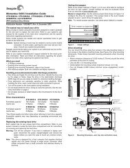
Figures 9a and 9b show the locations of the drive physical interface components for the various models of the<br />
drive. Shown are the locations of the DC power connector, the SCSI interface connector, and the drive select<br />
and option select headers.<br />
Details of the physical, electrical and logical characteristics are given in sections following, while the SCSI<br />
operational aspects of <strong>Seagate</strong> drive interfaces are given in the SCSI Interface Product Manual, part number<br />
77738479.<br />
This section describes the connectors, cables, signals, terminators and bus timing of the DC and SCSI I/O<br />
interface. See Section 9.8 and Section 9.9 for additional terminator information.<br />
9.6.1 DC cable and connector<br />
With the exception of the “<strong>LC</strong>” drives, the drive receives DC power through a 4 pin connector (see Figure 9a for<br />
pin assignment) mounted at the rear of the main PCBA. Recommended part numbers of the mating connector<br />
are listed below, but equivalent parts may be used.<br />
Type of cable Connector Contacts (20-14 AWG)<br />
14 AWG MP 1-480424-0 AMP 60619-4 (Loose Piece)<br />
AMP 61117-4 (Strip)<br />
Model “<strong>LC</strong>” receives power through the 80 pin I/O connector. See Table 13d.