Barracuda 18LP Family: ST39175LW/LC ST318275LW ... - Seagate
Barracuda 18LP Family: ST39175LW/LC ST318275LW ... - Seagate
Barracuda 18LP Family: ST39175LW/LC ST318275LW ... - Seagate

Create successful ePaper yourself
Turn your PDF publications into a flip-book with our unique Google optimized e-Paper software.
30 <strong>Barracuda</strong> <strong>18LP</strong> Product Manual, Rev. E<br />
[3]<br />
C<br />
G<br />
[1]<br />
E<br />
F<br />
D<br />
A<br />
Notes:<br />
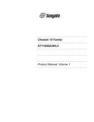
[1] Mounting holes three on each side, 6-32 UNC. Max screw length<br />
into side of drive 0.15 in. (3.81 mm). Screw tightening torque 6.0<br />
in-lb (.675 NM) max with minimum thread engagement of 0.12 in.<br />
(3.05 mm).<br />
L<br />
Pin 1<br />
B [4]<br />
Connector Centerline<br />
[2]<br />
[3]<br />
[4]<br />
Mounting holes four on bottom, 6-32 UNC. Max screw length into<br />
bottom of drive 0.15 in. (3.81 mm). Screw tightening torque 6.0<br />
in-lb (.675 NM) max with minimum thread engagement of 0.12 in.<br />
(3.05 mm).<br />
Interface connector is flush with the end of drive within<br />
±0.020 in. (.5 mm). The interface connector location may extend<br />
beyond HDA dimension “A” by 0.020 in. (.5 mm).<br />
Connector J1 is centered (side to side) on drive within ±0.020 in.<br />
(.508 mm).<br />
[5]<br />
Dimension “M” is from bottom rear drive mounting holes center(s)<br />
to the face of the connector at the center of the drive.<br />
X<br />
[7]<br />
[6]<br />
Dimensions “M” and “N” are unique requirements for SCA drives<br />
only, required for conformance with latest SFF Spec #8337.<br />
[7]<br />
N<br />
X<br />
M [5]<br />
[2]<br />
J<br />
[7] Maximum connector non-perpendicularity to side planes pointed<br />
to by X.<br />
[8] Centerline of pad for Pin 1 of J6.<br />
[9] Centerline of pad for Pin 1 of J2. Dimensions indicated are for<br />
reference only.<br />
U [9]<br />
[9] T<br />
H<br />
S [11]<br />
[13] K<br />
J2<br />
J6<br />
P [8]<br />
R<br />
LED<br />
[10] Dimensions to Pin 1 of each connector are nominal values.<br />
[11] To pin ends on J6. Pin ends on J6 are nominally flush with end of drive.<br />
[12] Nominal values cannot be added to any toleranced dimension to<br />
achieve a valid toleranced dimension.<br />
[13] Dimension “K” is from drive mounting hole to end of drive chasis<br />
(not the PCBA).<br />
[6]<br />
[7]<br />
A<br />
B<br />
C<br />
D<br />
E<br />
F<br />
G<br />
H<br />
J<br />
K<br />
L<br />
M<br />
N<br />
P<br />
R<br />
S<br />
T<br />
U<br />
Dimension Table<br />
Inches Millimeters<br />
5.75<br />
4.00<br />
1.002<br />
2.362<br />
1.120<br />
4.000<br />
.250<br />
1.750<br />
3.750<br />
2.380<br />
0.181<br />
1.625<br />
.015<br />
.405<br />
2.265<br />
2.350<br />
.165<br />
.753<br />
± .025<br />
± .015<br />
+ .027<br />
– .021<br />
± .010<br />
± .020<br />
± .010<br />
+ .010<br />
– .005<br />
± .010<br />
± .010<br />
± .010<br />
+ .015<br />
– .010<br />
± .02<br />
146.05<br />
101.60<br />
25.45<br />
60.00<br />
28.45<br />
101.60<br />
6.35<br />
44.45<br />
95.25<br />
60.45<br />
4.597<br />
41.28<br />
.38<br />
10.29<br />
52.53<br />
± .64<br />
± .38<br />
+ .69<br />
– .53<br />
± .25<br />
± .51<br />
± .25<br />
+ .25<br />
– .12<br />
± .25<br />
± .25<br />
± .25<br />
+ .38<br />
– .25<br />
± .50<br />
[10] 59.69<br />
4.19<br />
[10]<br />
19.13<br />
Figure 6b.<br />
Mounting configuration dimensions for “<strong>LC</strong>” model