You also want an ePaper? Increase the reach of your titles
YUMPU automatically turns print PDFs into web optimized ePapers that Google loves.
. . . . . . . . . . . . . . . . . . . . . . . . . . . . . . . . . . . . . . . . . . . . . . . . .<br />
Cheetah 18 Family:<br />
. . . . . . . . . . . . . . . . . . . . . . . . . . . . . . . . . . . . . . . . . . . . . . . . .<br />
ST118202LW/LC<br />
. . . . . . . . . . . . . . . . . . . . . . . . . . . . . . . . . . . . . . . . . . . . . . . . .<br />
. . . . . . . . . . . . . . . . . . . . . . . . . . . . . . . . . . . . . . . . . . . . . . . . .<br />
. . . . . . . . . . . . . . . . . . . . . . . . . . . . . . . . . . . . . . . . . . . . . . . . .<br />
<strong>Product</strong> <strong>Manual</strong>, Volume 1<br />
. . . . . . . . . . . . . . . . . . . . . . . . . . . . . . . . . . . . . . . . . . . . . . . . .
. . . . . . . . . . . . . . . . . . . . . . . . . . . . . . . . . . . . . . . . . . . . . . . . .<br />
Cheetah 18 Family:<br />
. . . . . . . . . . . . . . . . . . . . . . . . . . . . . . . . . . . . . . . . . . . . . . . . .<br />
ST118202LW/LC<br />
. . . . . . . . . . . . . . . . . . . . . . . . . . . . . . . . . . . . . . . . . . . . . . . . .<br />
. . . . . . . . . . . . . . . . . . . . . . . . . . . . . . . . . . . . . . . . . . . . . . . . .<br />
. . . . . . . . . . . . . . . . . . . . . . . . . . . . . . . . . . . . . . . . . . . . . . . . .<br />
<strong>Product</strong> <strong>Manual</strong>, Volume 1<br />
. . . . . . . . . . . . . . . . . . . . . . . . . . . . . . . . . . . . . . . . . . . . . . . . .
© 1997, 1998 Seagate Technology, Inc. All rights reserved<br />
Publication number: 83329260, Rev. B<br />
August 1998<br />
Seagate, Seagate Technology, and the Seagate logo are registered trademarks of Seagate Technology,<br />
Inc. Cheetah, SeaFAX, SeaFONE, SeaBOARD, and SeaTDD are either trademarks or registered trademarks<br />
of Seagate Technology, Inc. or one of its subsidiaries. All other trademarks or registered trademarks<br />
are the property of their respective owners.<br />
Seagate reserves the right to change, without notice, product offerings or specifications. No part of this<br />
publication may be reproduced in any form without written permission of Seagate Technology, Inc.
Revision status summary sheet<br />
Revision Date Writer/Engineer Sheets Affected<br />
Rev. A 05/19/98 L. Newman/J. Nowitzke 1/1, v thru viii, 1-69<br />
Rev. B 08/14/98 L. Newman/J. Nowitzke Add Multimode signal input and output<br />
characteristics to Section 9.<br />
Notice.<br />
<strong>Product</strong> <strong>Manual</strong> 83329260 is Volume 1 of a two volume document with the SCSI Interface information in<br />
the Volume 2 SCSI Interface <strong>Product</strong> <strong>Manual</strong>, part number 77738479.<br />
If the SCSI Interface information is needed the Volume 2 Interface <strong>Manual</strong> should be ordered,<br />
part number 77738479.
Cheetah 18 <strong>Product</strong> <strong>Manual</strong>, Rev. B<br />
v<br />
Contents<br />
1.0 Scope . . . . . . . . . . . . . . . . . . . . . . . . . . . . . . . . . . . . . . . . . . . . . . . . . . . . . . . . . . . . . . . . . . . . . . . . . . 1<br />
2.0 Applicable standards and reference documentation. . . . . . . . . . . . . . . . . . . . . . . . . . . . . . . . . . . . 3<br />
2.1 Standards. . . . . . . . . . . . . . . . . . . . . . . . . . . . . . . . . . . . . . . . . . . . . . . . . . . . . . . . . . . . . . . . . 3<br />
2.1.1 Electromagnetic <strong>com</strong>patibility . . . . . . . . . . . . . . . . . . . . . . . . . . . . . . . . . . . . . . . . . . 3<br />
2.1.2 Electromagnetic susceptibility. . . . . . . . . . . . . . . . . . . . . . . . . . . . . . . . . . . . . . . . . . 3<br />
2.2 Electromagnetic <strong>com</strong>pliance . . . . . . . . . . . . . . . . . . . . . . . . . . . . . . . . . . . . . . . . . . . . . . . . . . 3<br />
2.3 Reference documents . . . . . . . . . . . . . . . . . . . . . . . . . . . . . . . . . . . . . . . . . . . . . . . . . . . . . . . 4<br />
3.0 General description. . . . . . . . . . . . . . . . . . . . . . . . . . . . . . . . . . . . . . . . . . . . . . . . . . . . . . . . . . . . . . . 5<br />
3.1 Standard features. . . . . . . . . . . . . . . . . . . . . . . . . . . . . . . . . . . . . . . . . . . . . . . . . . . . . . . . . . . 7<br />
3.2 Media characteristics . . . . . . . . . . . . . . . . . . . . . . . . . . . . . . . . . . . . . . . . . . . . . . . . . . . . . . . . 7<br />
3.3 Performance. . . . . . . . . . . . . . . . . . . . . . . . . . . . . . . . . . . . . . . . . . . . . . . . . . . . . . . . . . . . . . . 7<br />
3.4 Reliability . . . . . . . . . . . . . . . . . . . . . . . . . . . . . . . . . . . . . . . . . . . . . . . . . . . . . . . . . . . . . . . . . 7<br />
3.5 Unformatted and formatted capacities . . . . . . . . . . . . . . . . . . . . . . . . . . . . . . . . . . . . . . . . . . . 8<br />
3.6 Programmable drive capacity. . . . . . . . . . . . . . . . . . . . . . . . . . . . . . . . . . . . . . . . . . . . . . . . . . 8<br />
3.7 Factory installed accessories . . . . . . . . . . . . . . . . . . . . . . . . . . . . . . . . . . . . . . . . . . . . . . . . . . 8<br />
3.8 Options (factory installed). . . . . . . . . . . . . . . . . . . . . . . . . . . . . . . . . . . . . . . . . . . . . . . . . . . . . 8<br />
3.9 Accessories (user installed) . . . . . . . . . . . . . . . . . . . . . . . . . . . . . . . . . . . . . . . . . . . . . . . . . . . 8<br />
4.0 Performance characteristics . . . . . . . . . . . . . . . . . . . . . . . . . . . . . . . . . . . . . . . . . . . . . . . . . . . . . . . 9<br />
4.1 Internal drive characteristics (transparent to user) . . . . . . . . . . . . . . . . . . . . . . . . . . . . . . . . 9<br />
4.2 SCSI performance characteristics (visible to user) . . . . . . . . . . . . . . . . . . . . . . . . . . . . . . . . . 9<br />
4.2.1 Access time . . . . . . . . . . . . . . . . . . . . . . . . . . . . . . . . . . . . . . . . . . . . . . . . . . . . . . . 9<br />
4.2.2 Format <strong>com</strong>mand execution time (minutes) . . . . . . . . . . . . . . . . . . . . . . . . . . . . . . . 9<br />
4.2.3 Generalized performance characteristics . . . . . . . . . . . . . . . . . . . . . . . . . . . . . . . . . 9<br />
4.3 Start/stop time . . . . . . . . . . . . . . . . . . . . . . . . . . . . . . . . . . . . . . . . . . . . . . . . . . . . . . . . . . . . 10<br />
4.4 Prefetch/multi-segmented cache control . . . . . . . . . . . . . . . . . . . . . . . . . . . . . . . . . . . . . . . . 10<br />
4.5 Cache operation . . . . . . . . . . . . . . . . . . . . . . . . . . . . . . . . . . . . . . . . . . . . . . . . . . . . . . . . . . . 10<br />
4.5.1 Caching write data . . . . . . . . . . . . . . . . . . . . . . . . . . . . . . . . . . . . . . . . . . . . . . . . . 11<br />
4.5.2 Prefetch operation . . . . . . . . . . . . . . . . . . . . . . . . . . . . . . . . . . . . . . . . . . . . . . . . . 12<br />
5.0 Reliability specifications . . . . . . . . . . . . . . . . . . . . . . . . . . . . . . . . . . . . . . . . . . . . . . . . . . . . . . . . . 13<br />
5.1 Error rates . . . . . . . . . . . . . . . . . . . . . . . . . . . . . . . . . . . . . . . . . . . . . . . . . . . . . . . . . . . . . . . 13<br />
5.1.1 Environmental interference. . . . . . . . . . . . . . . . . . . . . . . . . . . . . . . . . . . . . . . . . . . 13<br />
5.1.2 Read errors. . . . . . . . . . . . . . . . . . . . . . . . . . . . . . . . . . . . . . . . . . . . . . . . . . . . . . . 13<br />
5.1.3 Write errors . . . . . . . . . . . . . . . . . . . . . . . . . . . . . . . . . . . . . . . . . . . . . . . . . . . . . . . 13<br />
5.1.4 Seek errors . . . . . . . . . . . . . . . . . . . . . . . . . . . . . . . . . . . . . . . . . . . . . . . . . . . . . . . 13<br />
5.2 Reliability and service. . . . . . . . . . . . . . . . . . . . . . . . . . . . . . . . . . . . . . . . . . . . . . . . . . . . . . . 14<br />
5.2.1 Mean time between failure . . . . . . . . . . . . . . . . . . . . . . . . . . . . . . . . . . . . . . . . . . . 14<br />
5.2.2 Field failure rate vs time . . . . . . . . . . . . . . . . . . . . . . . . . . . . . . . . . . . . . . . . . . . . . 14<br />
5.2.3 Preventive maintenance . . . . . . . . . . . . . . . . . . . . . . . . . . . . . . . . . . . . . . . . . . . . . 15<br />
5.2.4 Service life . . . . . . . . . . . . . . . . . . . . . . . . . . . . . . . . . . . . . . . . . . . . . . . . . . . . . . . 15<br />
5.2.5 Service philosophy . . . . . . . . . . . . . . . . . . . . . . . . . . . . . . . . . . . . . . . . . . . . . . . . . 15<br />
5.2.6 Service tools . . . . . . . . . . . . . . . . . . . . . . . . . . . . . . . . . . . . . . . . . . . . . . . . . . . . . . 15<br />
5.2.7 Hot plugging Cheetah 18 disc drives . . . . . . . . . . . . . . . . . . . . . . . . . . . . . . . . . . . 15<br />
5.2.8 S.M.A.R.T. . . . . . . . . . . . . . . . . . . . . . . . . . . . . . . . . . . . . . . . . . . . . . . . . . . . . . . . 16<br />
5.2.9 <strong>Product</strong> warranty. . . . . . . . . . . . . . . . . . . . . . . . . . . . . . . . . . . . . . . . . . . . . . . . . . . 17<br />
6.0 Physical/electrical specifications . . . . . . . . . . . . . . . . . . . . . . . . . . . . . . . . . . . . . . . . . . . . . . . . . . 19<br />
6.1 AC power requirements . . . . . . . . . . . . . . . . . . . . . . . . . . . . . . . . . . . . . . . . . . . . . . . . . . . . . 19<br />
6.2 DC power requirements . . . . . . . . . . . . . . . . . . . . . . . . . . . . . . . . . . . . . . . . . . . . . . . . . . . . . 19<br />
6.2.1 Conducted noise immunity . . . . . . . . . . . . . . . . . . . . . . . . . . . . . . . . . . . . . . . . . . . 20<br />
6.2.2 Power sequencing . . . . . . . . . . . . . . . . . . . . . . . . . . . . . . . . . . . . . . . . . . . . . . . . . 20<br />
6.2.3 12 V - Current profile . . . . . . . . . . . . . . . . . . . . . . . . . . . . . . . . . . . . . . . . . . . . . . . 20<br />
6.3 Power dissipation . . . . . . . . . . . . . . . . . . . . . . . . . . . . . . . . . . . . . . . . . . . . . . . . . . . . . . . . . . 21<br />
6.4 Environmental limits . . . . . . . . . . . . . . . . . . . . . . . . . . . . . . . . . . . . . . . . . . . . . . . . . . . . . . . . 21<br />
6.4.1 Temperature . . . . . . . . . . . . . . . . . . . . . . . . . . . . . . . . . . . . . . . . . . . . . . . . . . . . . . 21
vi<br />
Cheetah 18 <strong>Product</strong> <strong>Manual</strong>, Rev. B<br />
6.4.2 Relative humidity . . . . . . . . . . . . . . . . . . . . . . . . . . . . . . . . . . . . . . . . . . . . . . . . . . .22<br />
6.4.3 Effective altitude (sea level). . . . . . . . . . . . . . . . . . . . . . . . . . . . . . . . . . . . . . . . . . .22<br />
6.4.4 Shock and vibration . . . . . . . . . . . . . . . . . . . . . . . . . . . . . . . . . . . . . . . . . . . . . . . . .23<br />
6.4.4.1 Shock . . . . . . . . . . . . . . . . . . . . . . . . . . . . . . . . . . . . . . . . . . . . . . . . .23<br />
6.4.4.2 Vibration . . . . . . . . . . . . . . . . . . . . . . . . . . . . . . . . . . . . . . . . . . . . . . .25<br />
6.4.5 Air cleanliness . . . . . . . . . . . . . . . . . . . . . . . . . . . . . . . . . . . . . . . . . . . . . . . . . . . . .25<br />
6.4.6 Acoustics . . . . . . . . . . . . . . . . . . . . . . . . . . . . . . . . . . . . . . . . . . . . . . . . . . . . . . . . .25<br />
6.4.7 Electromagnetic susceptibility . . . . . . . . . . . . . . . . . . . . . . . . . . . . . . . . . . . . . . . . .25<br />
6.5 Mechanical specifications . . . . . . . . . . . . . . . . . . . . . . . . . . . . . . . . . . . . . . . . . . . . . . . . . . . .26<br />
7.0 Defect and error management . . . . . . . . . . . . . . . . . . . . . . . . . . . . . . . . . . . . . . . . . . . . . . . . . . . . .29<br />
7.1 Drive internal defects. . . . . . . . . . . . . . . . . . . . . . . . . . . . . . . . . . . . . . . . . . . . . . . . . . . . . . . .29<br />
7.2 Drive error recovery procedures . . . . . . . . . . . . . . . . . . . . . . . . . . . . . . . . . . . . . . . . . . . . . . .29<br />
7.3 SCSI systems errors . . . . . . . . . . . . . . . . . . . . . . . . . . . . . . . . . . . . . . . . . . . . . . . . . . . . . . . .30<br />
8.0 Installation . . . . . . . . . . . . . . . . . . . . . . . . . . . . . . . . . . . . . . . . . . . . . . . . . . . . . . . . . . . . . . . . . . . . .31<br />
8.1 Drive ID/option select header . . . . . . . . . . . . . . . . . . . . . . . . . . . . . . . . . . . . . . . . . . . . . . . . .31<br />
8.1.1 Notes for Figures 8, 9, and 10. . . . . . . . . . . . . . . . . . . . . . . . . . . . . . . . . . . . . . . . .34<br />
8.1.2 Function description. . . . . . . . . . . . . . . . . . . . . . . . . . . . . . . . . . . . . . . . . . . . . . . . .35<br />
8.2 Drive orientation . . . . . . . . . . . . . . . . . . . . . . . . . . . . . . . . . . . . . . . . . . . . . . . . . . . . . . . . . . .36<br />
8.3 Cooling . . . . . . . . . . . . . . . . . . . . . . . . . . . . . . . . . . . . . . . . . . . . . . . . . . . . . . . . . . . . . . . . . .36<br />
8.3.1 Air flow . . . . . . . . . . . . . . . . . . . . . . . . . . . . . . . . . . . . . . . . . . . . . . . . . . . . . . . . . . .36<br />
8.4 Drive mounting . . . . . . . . . . . . . . . . . . . . . . . . . . . . . . . . . . . . . . . . . . . . . . . . . . . . . . . . . . . .37<br />
8.5 Grounding . . . . . . . . . . . . . . . . . . . . . . . . . . . . . . . . . . . . . . . . . . . . . . . . . . . . . . . . . . . . . . . .37<br />
9.0 Interface requirements. . . . . . . . . . . . . . . . . . . . . . . . . . . . . . . . . . . . . . . . . . . . . . . . . . . . . . . . . . . .39<br />
9.1 General description . . . . . . . . . . . . . . . . . . . . . . . . . . . . . . . . . . . . . . . . . . . . . . . . . . . . . . . . .39<br />
9.2 SCSI interface messages supported. . . . . . . . . . . . . . . . . . . . . . . . . . . . . . . . . . . . . . . . . . . .39<br />
9.3 SCSI interface <strong>com</strong>mands supported . . . . . . . . . . . . . . . . . . . . . . . . . . . . . . . . . . . . . . . . . . .40<br />
9.3.1 Inquiry Vital <strong>Product</strong> data. . . . . . . . . . . . . . . . . . . . . . . . . . . . . . . . . . . . . . . . . . . . .43<br />
9.3.2 Mode Sense data. . . . . . . . . . . . . . . . . . . . . . . . . . . . . . . . . . . . . . . . . . . . . . . . . . .44<br />
9.4 SCSI bus conditions and miscellaneous features supported . . . . . . . . . . . . . . . . . . . . . . . . .46<br />
9.5 Synchronous data transfer . . . . . . . . . . . . . . . . . . . . . . . . . . . . . . . . . . . . . . . . . . . . . . . . . . .47<br />
9.5.1 Synchronous data transfer periods supported. . . . . . . . . . . . . . . . . . . . . . . . . . . . .47<br />
9.5.2 REQ/ACK offset. . . . . . . . . . . . . . . . . . . . . . . . . . . . . . . . . . . . . . . . . . . . . . . . . . . .47<br />
9.6 Physical interface . . . . . . . . . . . . . . . . . . . . . . . . . . . . . . . . . . . . . . . . . . . . . . . . . . . . . . . . . .47<br />
9.6.1 DC cable and connector . . . . . . . . . . . . . . . . . . . . . . . . . . . . . . . . . . . . . . . . . . . . .47<br />
9.6.2 SCSI interface physical description . . . . . . . . . . . . . . . . . . . . . . . . . . . . . . . . . . . . .49<br />
9.6.3 SCSI interface cable requirements . . . . . . . . . . . . . . . . . . . . . . . . . . . . . . . . . . . . .49<br />
9.6.4 Mating connectors . . . . . . . . . . . . . . . . . . . . . . . . . . . . . . . . . . . . . . . . . . . . . . . . . .50<br />
9.6.4.1 Mating connectors for LW drives. . . . . . . . . . . . . . . . . . . . . . . . . . . . .50<br />
9.6.4.2 Mating connectors for LC drives . . . . . . . . . . . . . . . . . . . . . . . . . . . . .50<br />
9.7 Electrical description . . . . . . . . . . . . . . . . . . . . . . . . . . . . . . . . . . . . . . . . . . . . . . . . . . . . . . . .58<br />
9.7.1 Multimode—SE and LVD alternatives . . . . . . . . . . . . . . . . . . . . . . . . . . . . . . . . . . .58<br />
9.7.1.1 Single-ended drivers/receivers . . . . . . . . . . . . . . . . . . . . . . . . . . . . . .60<br />
9.7.1.2 Low voltage differential I/O circuits . . . . . . . . . . . . . . . . . . . . . . . . . . .60<br />
9.7.1.3 General cable characteristics . . . . . . . . . . . . . . . . . . . . . . . . . . . . . . .60<br />
9.8 Terminator requirements . . . . . . . . . . . . . . . . . . . . . . . . . . . . . . . . . . . . . . . . . . . . . . . . . . . . .60<br />
9.9 Terminator power . . . . . . . . . . . . . . . . . . . . . . . . . . . . . . . . . . . . . . . . . . . . . . . . . . . . . . . . . .60<br />
9.10 Disc drive SCSI timing. . . . . . . . . . . . . . . . . . . . . . . . . . . . . . . . . . . . . . . . . . . . . . . . . . . . . . .61<br />
10.0 Seagate technical support services . . . . . . . . . . . . . . . . . . . . . . . . . . . . . . . . . . . . . . . . . . . . . . . . .63
Cheetah 18 <strong>Product</strong> <strong>Manual</strong>, Rev. B<br />
vii<br />
List of Figures<br />
Figure 1. Cheetah 18 family drive (ST118202LW shown). . . . . . . . . . . . . . . . . . . . . . . . . . . . . . . . . . . . 1<br />
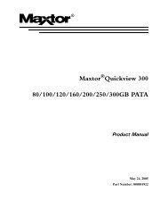
Figure 2. Cheetah 18 family drive . . . . . . . . . . . . . . . . . . . . . . . . . . . . . . . . . . . . . . . . . . . . . . . . . . . . . . 6<br />
Figure 3. Typical Cheetah 18 family drive +12 V current profile . . . . . . . . . . . . . . . . . . . . . . . . . . . . . . 20<br />
Figure 4. Locations of PCBA <strong>com</strong>ponents listed in Table 3 . . . . . . . . . . . . . . . . . . . . . . . . . . . . . . . . . 22<br />
Figure 5. Re<strong>com</strong>mended mounting . . . . . . . . . . . . . . . . . . . . . . . . . . . . . . . . . . . . . . . . . . . . . . . . . . . . 24<br />
Figure 6. ST118202LW mounting configuration dimensions. . . . . . . . . . . . . . . . . . . . . . . . . . . . . . . . . 26<br />
Figure 7. ST118202LC mounting configuration dimensions . . . . . . . . . . . . . . . . . . . . . . . . . . . . . . . . . 27<br />
Figure 8. J6 jumper header . . . . . . . . . . . . . . . . . . . . . . . . . . . . . . . . . . . . . . . . . . . . . . . . . . . . . . . . . . 32<br />
Figure 9. J5 jumper header (on LW models only) . . . . . . . . . . . . . . . . . . . . . . . . . . . . . . . . . . . . . . . . . 33<br />
Figure 10. J2 option select header . . . . . . . . . . . . . . . . . . . . . . . . . . . . . . . . . . . . . . . . . . . . . . . . . . . . . 34<br />
Figure 11. Air flow (suggested) . . . . . . . . . . . . . . . . . . . . . . . . . . . . . . . . . . . . . . . . . . . . . . . . . . . . . . . . 36<br />
Figure 12. ST118202LW drive physical interface (68-pin J1 SCSI I/O connector) . . . . . . . . . . . . . . . . . 48<br />
Figure 13. ST118202LC drive physical interface (80-pin J1 SCSI I/O connector) . . . . . . . . . . . . . . . . . 48<br />
Figure 14. SCSI daisy chain interface cabling LW drives . . . . . . . . . . . . . . . . . . . . . . . . . . . . . . . . . . . . 51<br />
Figure 15. Nonshielded 68 pin SCSI device connector used on LW drives . . . . . . . . . . . . . . . . . . . . . . 52<br />
Figure 16. Nonshielded 80 pin SCSI “SCA-2” connector, used on LC drives . . . . . . . . . . . . . . . . . . . . . 53<br />
Figure 17. LVD output signals . . . . . . . . . . . . . . . . . . . . . . . . . . . . . . . . . . . . . . . . . . . . . . . . . . . . . . . . . 59<br />
Figure 18. Typical SE-LVD alternative transmitter receiver circuits . . . . . . . . . . . . . . . . . . . . . . . . . . . . 59
Cheetah 18 <strong>Product</strong> <strong>Manual</strong>, Rev. B 1<br />
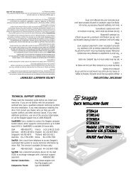
1.0 Scope<br />
This manual describes Seagate Technology®, Inc. Cheetah 18 disc drives.<br />
Cheetah 18 drives support the small <strong>com</strong>puter system interface (SCSI) as described in the ANSI SCSI, SCSI-<br />
2, and SCSI-3 (Fast-20 and Fast-40) interface specifications to the extent described in this manual. The SCSI<br />
Interface <strong>Product</strong> <strong>Manual</strong> (part number 77738479) describes general SCSI interface characteristics of this and<br />
other families of Seagate drives.<br />
From this point on in this product manual the reference to Cheetah 18 models is referred to as “the drive”<br />
unless references to individual models are necessary.<br />
*<br />
Figure 1.<br />
Cheetah 18 family drive (ST118202LW shown)
Cheetah 18 <strong>Product</strong> <strong>Manual</strong>, Rev. B 3<br />
2.0 Applicable standards and reference documentation<br />
The drive has been developed as a system peripheral to the highest standards of design and construction. The<br />
drive depends upon its host equipment to provide adequate power and environment in order to achieve optimum<br />
performance and <strong>com</strong>pliance with applicable industry and governmental regulations. Special attention<br />
must be given in the areas of safety, power distribution, shielding, audible noise control, and temperature regulation.<br />
In particular, the drive must be securely mounted in order to guarantee the specified performance characteristics.<br />
Mounting by bottom holes must meet the requirements of Section 8.4.<br />
2.1 Standards<br />
The Cheetah 18 family <strong>com</strong>plies with Seagate standards as noted in the appropriate sections of this <strong>Manual</strong><br />
and the Seagate SCSI Interface <strong>Product</strong> <strong>Manual</strong>, part number 77738479 (Vol. 2).<br />
The Cheetah 18 disc drive is a UL recognized <strong>com</strong>ponent per UL1950, CSA certified to CSA C22.2 No. 950-<br />
M89, and VDE certified to VDE 0805 and EN60950.<br />
2.1.1 Electromagnetic <strong>com</strong>patibility<br />
The drive, as delivered, is designed for system integration and installation into a suitable enclosure prior to use.<br />
As such the drive is supplied as a subassembly and is not subject to Subpart B of Part 15 of the FCC Rules<br />
and Regulations nor the Radio Interference Regulations of the Canadian Department of Communications.<br />
The design characteristics of the drive serve to minimize radiation when installed in an enclosure that provides<br />
reasonable shielding. As such, the drive is capable of meeting the Class B limits of the FCC Rules and Regulations<br />
of the Canadian Department of Communications when properly packaged. However, it is the user’s<br />
responsibility to assure that the drive meets the appropriate EMI requirements in their system. Shielded I/O<br />
cables may be required if the enclosure does not provide adequate shielding. If the I/O cables are external to<br />
the enclosure, shielded cables should be used, with the shields grounded to the enclosure and to the host controller.<br />
2.1.2 Electromagnetic susceptibility<br />
As a <strong>com</strong>ponent assembly, the drive is not required to meet any susceptibility performance requirements. It is<br />
the responsibility of those integrating the drive within their systems to perform those tests required and design<br />
their system to ensure that equipment operating in the same system as the drive or external to the system<br />
does not adversely affect the performance of the drive. See Section 5.1.1 and Table 2, DC power requirements.<br />
2.2 Electromagnetic <strong>com</strong>pliance<br />
Seagate uses an independent laboratory to confirm <strong>com</strong>pliance to the directives/standard(s) for CE Marking<br />
and C-Tick Marking. The drive was tested in a representative system for typical applications. The selected system<br />
represents the most popular characteristics for test platforms. The system configurations include:<br />
• 486, Pentium, and PowerPC microprocessors<br />
• 3.5-inch floppy disc drive<br />
• Keyboard<br />
• Monitor/display<br />
• Printer<br />
• External modem<br />
• Mouse<br />
Although the test system with this Seagate model <strong>com</strong>plies to the directives/standard(s), we cannot guarantee<br />
that all systems will <strong>com</strong>ply. The <strong>com</strong>puter manufacturer or system integrator shall confirm EMC <strong>com</strong>pliance<br />
and provide CE Marking and C-Tick Marking for their product.<br />
Electromagnetic <strong>com</strong>pliance for the European Union<br />
If this model has the CE Marking it <strong>com</strong>plies with the European Union requirements of the Electromagnetic<br />
Compatibility Directive 89/336/EEC of 03 May 1989 as amended by Directive 92/31/EEC of 28 April 1992 and<br />
Directive 93/68/EEC of 22 July 1993.
4 Cheetah 18 <strong>Product</strong> <strong>Manual</strong>, Rev. B<br />
Australian C-Tick<br />
If this model has the C-Tick Marking it <strong>com</strong>plies with the Australia/New Zealand Standard AS/NZS3548 1995<br />
and meets the Electromagnetic Compatibility (EMC) Framework requirements of Australia’s Spectrum Management<br />
Agency (SMA).<br />
2.3 Reference documents<br />
Cheetah 18 Installation Guide Seagate P/N 83329250<br />
SCSI Interface <strong>Product</strong> <strong>Manual</strong> Seagate P/N 77738479<br />
ANSI small <strong>com</strong>puter system interface (SCSI) document numbers:<br />
X3.131-1994<br />
SCSI-2<br />
X3.253-1995<br />
SCSI-3 Parallel Interface<br />
T10/1142D Rev. 14 SPI-2 (SCSI-3 Parallel Interface version 2)<br />
SFF-8046 Specification for 80-pin connector for SCSI disk drives<br />
SCA-2 EIA Specification ANSI/EIA<br />
68-pin EIA # 3652<br />
Package Test Specification<br />
Package Test Specification<br />
Seagate P/N 30190-001 (under 100 lb.)<br />
Seagate P/N 30191-001 (over 100 lb.)<br />
Specification, Acoustic Test Requirements, and Procedures Seagate P/N 30553-001<br />
In case of conflict between this document and any referenced document, this document takes precedence.
Cheetah 18 <strong>Product</strong> <strong>Manual</strong>, Rev. B 5<br />
3.0 General description<br />
Cheetah 18 drives <strong>com</strong>bine magnetoresistive (MR) heads, partial response/maximum likelihood (PRML) read<br />
channel electronics, embedded servo technology, and a wide Ultra2 SCSI interface to provide high performance,<br />
high capacity data storage for a variety of systems including engineering workstations, network servers,<br />
mainframes, and super<strong>com</strong>puters.<br />
Ultra SCSI and Ultra2 SCSI use negotiated transfer rates. These transfer rates will occur only if your host<br />
adapter supports these data transfer rates and is <strong>com</strong>patible with the required hardware requirements of the<br />
I/O circuit type. This drive also operates at SCSI-1 and SCSI-2 data transfer rates for backward <strong>com</strong>patibility<br />
with non-Ultra/Ultra2 SCSI host adapters.<br />
Table 1 lists the features that differentiate the two Cheetah 18 models.<br />
Table 1:<br />
Drive model number vs. differentiating features<br />
Model number<br />
Number<br />
of heads I/O circuit type [1]<br />
Number of I/O<br />
connector pins<br />
Number of I/O<br />
data bus bits<br />
ST118202LW 24 Multimode—single-ended (SE)<br />
and low voltage differential (LVD)<br />
ST118202LC 24 Multimode—single-ended (SE)<br />
and low voltage differential (LVD)<br />
68 16<br />
80 16<br />
[1] See Section 9.6 for details and definitions.<br />
The drive records and recovers data on approximately 3-inch (84 mm) non-removeable discs.<br />
The drive supports the Small Computer System Interface (SCSI) as described in the ANSI SCSI-2/SCSI-3<br />
interface specifications to the extent described in this manual (volume 1), which defines the product performance<br />
characteristics of the Cheetah 18 family of drives, and the SCSI Interface <strong>Product</strong> <strong>Manual</strong> (volume 2),<br />
part number 77738479, which describes the general interface characteristics of this and other families of<br />
Seagate SCSI drives.<br />
The drive’s interface supports multiple initiators, disconnect/reconnect, self-configuring host software, and<br />
automatic features that relieve the host from the necessity of knowing the physical characteristics of the targets<br />
(logical block addressing is used).<br />
The head and disc assembly (HDA) is sealed at the factory. Air circulates within the HDA through a nonreplaceable<br />
filter to maintain a contamination-free HDA environment.<br />
Refer to Figure 2 for an exploded view of the drive. This exploded view is for information only—never disassemble<br />
the HDA and do not attempt to service items in the sealed enclosure (heads, media, actuator, etc.) as this<br />
requires special facilities. The drive contains no replaceable parts. Opening the HDA voids your warranty.<br />
Cheetah 18 drives use a dedicated landing zone at the innermost radius of the media to eliminate the possibility<br />
of destroying or degrading data by landing in the data zone. The drive automatically goes to the landing<br />
zone when power is removed.<br />
An automatic shipping lock prevents potential damage to the heads and discs that results from movement during<br />
shipping and handling. The shipping lock automatically disengages when power is applied to the drive and<br />
the head load process begins.<br />
Cheetah 18 drives decode track 0 location data from the servo data embedded on each surface to eliminate<br />
mechanical transducer adjustments and related reliability concerns.<br />
A high-performance actuator assembly with a low-inertia, balanced, patented, straight-arm design provides<br />
excellent performance with minimal power dissipation.
6 Cheetah 18 <strong>Product</strong> <strong>Manual</strong>, Rev. B<br />
Figure 2.<br />
Cheetah 18 family drive
Cheetah 18 <strong>Product</strong> <strong>Manual</strong>, Rev. B 7<br />
3.1 Standard features<br />
The Cheetah 18 family has the following standard features:<br />
• Integrated Ultra/Ultra2 SCSI controller<br />
• Multimode SCSI drivers and receivers—single-ended (SE) and low voltage differential (LVD)<br />
• 16 bit I/O data bus<br />
• Asynchronous and synchronous data transfer protocol<br />
• Firmware downloadable via SCSI interface<br />
• Selectable even byte sector sizes from 180 to 4,096 bytes/sector<br />
• Programmable sector reallocation scheme<br />
• Flawed sector reallocation at format time<br />
• Programmable auto write and read reallocation<br />
• Reallocation of defects on <strong>com</strong>mand (post format)<br />
• Enhanced ECC correction capability up to 185 bits<br />
• Sealed head and disc assembly<br />
• No preventative maintenance or adjustment required<br />
• Dedicated head landing zone<br />
• Embedded servo design<br />
• Self diagnostics performed when power is applied to the drive<br />
• 1:1 Interleave<br />
• Zoned bit recording (ZBR)<br />
• Vertical, horizontal, or top down mounting<br />
• Dynamic spindle brake<br />
• 1,024 kbyte data buffer (or 4,096 kbyte option)<br />
• Hot plug <strong>com</strong>patibility (Section 9.6.4.2 lists proper host connector needed) for “LC” model drives<br />
• SCAM (SCSI Configured AutoMagically) plug-n-play level 2 <strong>com</strong>pliant, factory set to level 1<br />
3.2 Media characteristics<br />
The media used on the drive has a diameter of approximately 3 inches (84 mm). The aluminum substrate is<br />
coated with a thin film magnetic material, overcoated with a proprietary protective layer for improved durability<br />
and environmental protection.<br />
3.3 Performance<br />
• Supports industry standard Ultra2 SCSI interface<br />
• Programmable multi-segmentable cache buffer (see Section 3.1)<br />
• 10,025 RPM spindle. Average latency = 2.99 ms<br />
• Command queuing of up to 64 <strong>com</strong>mands<br />
• Background processing of queue<br />
• Supports start and stop <strong>com</strong>mands (spindle stops spinning)<br />
3.4 Reliability<br />
• 1,000,000 hour MTBF<br />
• LSI circuitry<br />
• Balanced low mass rotary voice coil actuator<br />
• Incorporates industry-standard Self-Monitoring, Analysis and Reporting Technology (S.M.A.R.T.)<br />
• 5-year warranty
8 Cheetah 18 <strong>Product</strong> <strong>Manual</strong>, Rev. B<br />
3.5 Unformatted and formatted capacities<br />
Formatted capacity depends on the number of spare reallocation sectors reserved and the number of bytes per<br />
sector. The following table shows the standard OEM model capacities:<br />
Formatted<br />
data block size<br />
512 bytes/sector [1] Unformatted<br />
ST118202 021EB38Fh (18.210 GB) [2] 22.54 GB<br />
Notes.<br />
[1] Sector size selectable at format time. Users having the necessary equipment may modify the data block<br />
size before issuing a format <strong>com</strong>mand and obtain different formatted capacities than those listed. See<br />
Mode Select Command and Format Command in the SCSI Interface <strong>Product</strong> <strong>Manual</strong>, part number<br />
77738479.<br />
[2] User available capacity depends on spare reallocation scheme selected, the number of data tracks per<br />
sparing zone, and the number of alternate sectors (LBAs) per sparing zone.<br />
3.6 Programmable drive capacity<br />
Using the Mode Select <strong>com</strong>mand, the drive can change its capacity to something less than maximum. See<br />
Table 5.2.1-13 in the SCSI Interface <strong>Product</strong> <strong>Manual</strong>, part number 77738479, Rev. H. Refer to the Parameter<br />
list block descriptor number of blocks field. A value of zero in the number of blocks field indicates that the drive<br />
shall not change the capacity it is currently formatted to have. A number in the number of blocks field that is<br />
less than the maximum number of LBAs changes the total drive capacity to the value in the block descriptor<br />
number of blocks field. A value greater than the maximum number of LBAs is rounded down to the maximum<br />
capacity.<br />
3.7 Factory installed accessories<br />
OEM Standard drives are shipped with the Cheetah 18 Installation Guide, part number 83329250 (unless otherwise<br />
specified). The factory also ships with the drive a small bag of jumper plugs used for the J2, J5, and J6<br />
option select jumper headers.<br />
3.8 Options (factory installed)<br />
All customer requested options are incorporated during production or packaged at the manufacturing facility<br />
before shipping. Some of the options available are (not an exhaustive list of possible options):<br />
• Other capacities can be ordered depending on sparing scheme and sector size requested.<br />
• 4 Mbyte optional buffer size.<br />
• Single unit shipping pack. The drive is normally shipped in bulk packaging to provide maximum protection<br />
against transit damage. Units shipped individually require additional protection as provided by the single unit<br />
shipping pack. Users planning single unit distribution should specify this option.<br />
• The Cheetah 18 Installation Guide, part number 83329250, is usually included with each standard OEM<br />
drive shipped, but extra copies may be ordered.<br />
3.9 Accessories (user installed)<br />
The following accessories are available. All accessories may be installed in the field.<br />
• Single unit shipping pack.
Cheetah 18 <strong>Product</strong> <strong>Manual</strong>, Rev. B 9<br />
4.0 Performance characteristics<br />
4.1 Internal drive characteristics (transparent to user)<br />
ST118202<br />
Drive capacity 18.210 GByte (formatted, rounded off values)<br />
Read/write heads 24<br />
Bytes/track 104,840–159,008 Bytes (average, rounded off values)<br />
Mbytes/surface 939 Mbytes (unformatted, rounded off values)<br />
Tracks/surface (total) 6,962 Tracks (user accessible)<br />
Tracks/inch 8,962 TPI<br />
Peak bits/inch 183 KBPI<br />
Internal data rate 152-231 Mbits/sec (variable with zone)<br />
Disc rotational speed 10,025 r/min<br />
Average rotational latency 2.99 msec<br />
4.2 SCSI performance characteristics (visible to user)<br />
The values given in Section 4.2.1 apply to all models of the Cheetah 18 family unless otherwise specified.<br />
Refer to Section 9.10 and to the SCSI Interface <strong>Product</strong> <strong>Manual</strong>, part number 77738479, for additional timing<br />
details.<br />
4.2.1 Access time [5]<br />
Including controller overhead<br />
(without disconnect) [1] [3]<br />
Drive level<br />
Read Write<br />
msec<br />
Average – Typical [2] 6.0 6.8<br />
Single Track – Typical [2] 0.8 1.1<br />
Full Stroke – Typical [2] 12.2 13.2<br />
4.2.2 Format <strong>com</strong>mand execution time (minutes) [1]<br />
ST118202<br />
Maximum (with verify)
10 Cheetah 18 <strong>Product</strong> <strong>Manual</strong>, Rev. B<br />
Sector Sizes:<br />
Default<br />
Variable<br />
512 byte user data blocks<br />
180 to 4,096 bytes per sector in even number of<br />
bytes per sector.<br />
If n (number of bytes per sector) is odd, then n-1<br />
will be used.<br />
Read/write consecutive sectors on a track Yes<br />
Flaw reallocation performance impact (for flaws reallocated at format time using<br />
the spare sectors per sparing zone reallocation scheme.)<br />
Overhead time for head switch (512 byte sectors) in sequential mode<br />
Overhead time for one track cylinder switch in sequential mode<br />
Average rotational latency<br />
Negligible<br />
0.8 msec<br />
1.2 msec (typical)<br />
2.99 msec<br />
Notes for Section 4.2.<br />
[1] Execution time measured from receipt of the last Byte of the Command Descriptor Block (CDB) to the<br />
request for a Status Byte Transfer to the Initiator (excluding connect/disconnect).<br />
[2] Typical access times are measured under nominal conditions of temperature, voltage, and horizontal orientation<br />
as measured on a representative sample of drives.<br />
[3] Assumes no errors and no sector has been relocated.<br />
[4] Assumes system ability to support the rates listed and no cable loss.<br />
[5] Access time = controller overhead + average seek time.<br />
Access to data = controller overhead + average seek time + latency time.<br />
4.3 Start/stop time<br />
After DC power at nominal voltage has been applied, the drive be<strong>com</strong>es ready within 30 seconds if the Motor<br />
Start Option is disabled (i.e. the motor starts as soon as the power has been applied). If a recoverable error<br />
condition is detected during the start sequence, the drive executes a recovery procedure which may cause the<br />
time to be<strong>com</strong>e ready to exceed 30 seconds. During spin up to ready time the drive responds to some <strong>com</strong>mands<br />
over the SCSI interface in less than 3 seconds after application of power. Stop time is less than 30 seconds<br />
from removal of DC power.<br />
If the Motor Start Option is enabled, the internal controller accepts the <strong>com</strong>mands listed in the SCSI Interface<br />
<strong>Product</strong> <strong>Manual</strong> less than 3 seconds after DC power has been applied. After the Motor Start Command has<br />
been received the drive be<strong>com</strong>es ready for normal operations within 30 seconds typically (excluding an error<br />
recovery procedure). The Motor Start Command can also be used to <strong>com</strong>mand the drive to stop the spindle<br />
(see SCSI Interface <strong>Product</strong> <strong>Manual</strong>, part number 77738479).<br />
There is no power control switch on the drive.<br />
4.4 Prefetch/multi-segmented cache control<br />
The drive provides prefetch (read look-ahead) and multi-segmented cache control algorithms that in many<br />
cases can enhance system performance. “Cache” as used herein refers to the drive buffer storage space when<br />
it is used in cache operations. To select prefetch and cache features the host sends the Mode Select <strong>com</strong>mand<br />
with the proper values in the applicable bytes in Mode Page 08h (see SCSI Interface <strong>Product</strong> <strong>Manual</strong>, part<br />
number 77738479. Prefetch and cache operation are independent features from the standpoint that each is<br />
enabled and disabled independently via the Mode Select <strong>com</strong>mand. However, in actual operation the prefetch<br />
feature overlaps cache operation somewhat as is noted in Section 4.5.1 and 4.5.2.<br />
All default cache and prefetch Mode parameter values (Mode Page 08h) for standard OEM versions of this<br />
drive family are given in Tables 8.<br />
4.5 Cache operation<br />
In general, 840 Kbytes (3,700 kbytes of the 4,096 kbytes on units with this option) of the physical buffer space<br />
in the drive can be used as storage space for cache operations. The buffer can be divided into logical segments<br />
(Mode Select Page 08h, byte 13) from which data is read and to which data is written. The drive main-
Cheetah 18 <strong>Product</strong> <strong>Manual</strong>, Rev. B 11<br />
tains a table of logical block disk medium addresses of the data stored in each segment of the buffer. If cache<br />
operation is enabled (RCD bit = 0 in Mode Page 08h, byte 2, bit 0. See SCSI Interface <strong>Product</strong> <strong>Manual</strong>, part<br />
number 77738479), data requested by the host with a Read <strong>com</strong>mand is retrieved from the buffer (if it is there),<br />
before any disc access is initiated. If cache operation is not enabled, the buffer (still segmented with required<br />
number of segments) is still used, but only as circular buffer segments during disc medium read operations<br />
(disregarding Prefetch operation for the moment). That is, the drive does not check in the buffer segments for<br />
the requested read data, but goes directly to the medium to retrieve it. The retrieved data merely passes<br />
through some buffer segment on the way to the host. On a cache miss, all data transfers to the host are in<br />
accordance with buffer-full ratio rules. On a cache hit the drive ignores the buffer-full ratio rules. See explanations<br />
associated with Mode page 02h (disconnect/reconnect control) in the SCSI Interface <strong>Product</strong> <strong>Manual</strong>.<br />
The following is a simplified description of a read operation with cache operation enabled:<br />
Case A - A Read <strong>com</strong>mand is received and the first logical block (LB) is already in cache:<br />
1. Drive transfers to the initiator the first LB requested plus all subsequent contiguous LBs that are already in<br />
the cache. This data may be in multiple segments.<br />
2. When the requested LB is reached that is not in any cache segment, the drive fetches it and any remaining<br />
requested LBs from the disc and puts them in a segment of the cache. The drive transfers the remaining<br />
requested LBs from the cache to the host in accordance with the disconnect/reconnect specification mentioned<br />
above.<br />
3. If the prefetch feature is enabled, refer to Section 4.5.2 for operation from this point.<br />
Case B - A Read <strong>com</strong>mand requests data, the first LB of which is not in any segment of the cache:<br />
1. The drive fetches the requested LBs from the disc and transfers them into a segment, and from there to the<br />
host in accordance with the disconnect/reconnect specification referred to in case A.<br />
2. If the prefetch feature is enabled, refer to Section 4.5.2 for operation from this point.<br />
Each buffer segment is actually a self-contained circular storage (wrap-around occurs), the length of which is<br />
an integer number of disc medium sectors. The wrap-around capability of the individual segments greatly<br />
enhances the buffer’s overall performance as a cache storage, allowing a wide range of user selectable configurations,<br />
which includes their use in the prefetch operation (if enabled), even when cache operation is disabled<br />
(see Section 4.5.2). The number of segments may be selected using the Mode Select <strong>com</strong>mand, but the size<br />
can not be directly selected. Size is selected only as a by-product of selecting the segment number specification.<br />
The size in Kbytes of each segment is not reported by the Mode Sense <strong>com</strong>mand page 08h, bytes 14 and<br />
15. The value 0XFFFF is always reported. If a size specification is sent by the host in a Mode Select <strong>com</strong>mand<br />
(bytes 14 and 15) no new segment size is set up by the drive, and if the STRICT bit in Mode page 00h (byte 2,<br />
bit 1) is set to one, the drive responds as it does for any attempt to change unchangeable parameters (see<br />
SCSI Interface <strong>Product</strong> <strong>Manual</strong>, part number 77738479). The drive supports operation of any integer number<br />
of segments from 1 to 16. Default is three segments.<br />
4.5.1 Caching write data<br />
Write caching is a write operation by the drive that makes use of a drive buffer storage area where the data to<br />
be written to the medium is stored in one or more segments while the drive performs the write <strong>com</strong>mand.<br />
If read caching is enabled (RCD=0), then data written to the medium is retained in the cache to be made available<br />
for future read cache hits. The same buffer space and segmentation is used as set up for read functions.<br />
The buffer segmentation scheme is set up or changed independently, having nothing to do with the state of<br />
RCD. When a write <strong>com</strong>mand is issued, if RCD=0, the cache is first checked to see if any logical blocks that<br />
are to be written are already stored in the cache from a previous read or write <strong>com</strong>mand. If there are, the<br />
respective cache segments are cleared. The new data is cached for subsequent Read <strong>com</strong>mands.<br />
If the number of write data logical blocks exceeds the size of the segment being written into, when the end of<br />
the segment is reached, the data is written into the beginning of the same cache segment, overwriting the data<br />
that was written there at the beginning of the operation. However, the drive does not overwrite data that has not<br />
yet been written to the medium.<br />
If write caching is enabled (WCE=1), then the drive may return GOOD status on a write <strong>com</strong>mand after the<br />
data has been transferred into the cache, but before the data has been written to the medium. If an error occurs
12 Cheetah 18 <strong>Product</strong> <strong>Manual</strong>, Rev. B<br />
while writing the data to the medium, and GOOD status has already been returned, a deferred error will be<br />
generated.<br />
The Synchronize Cache <strong>com</strong>mand may be used to force the drive to write all cached write data to the medium.<br />
Upon <strong>com</strong>pletion of a Synchronize Cache <strong>com</strong>mand, all data received from previous write <strong>com</strong>mands will have<br />
been written to the medium.<br />
Tables 8 show Mode default settings for the drives.<br />
4.5.2 Prefetch operation<br />
If the Prefetch feature is enabled, data in contiguous logical blocks on the disc immediately beyond that which<br />
was requested by a Read <strong>com</strong>mand can be retrieved and stored in the buffer for immediate transfer from the<br />
buffer to the host on subsequent Read <strong>com</strong>mands that request those logical blocks (this is true even if cache<br />
operation is disabled). Though the prefetch operation uses the buffer as a cache, finding the requested data in<br />
the buffer is a prefetch hit, not a cache operation hit. Prefetch is enabled using Mode Select page 08h, byte 12,<br />
bit 5 (Disable Read Ahead - DRA bit). DRA bit = 0 enables prefetch. Since data that is prefetched replaces data<br />
already in some buffer segment(s), the host can limit the amount of prefetch data to optimize system performance.<br />
The max prefetch field (bytes 8 and 9) limits the amount of prefetch. The drive does not use the<br />
Prefetch Ceiling field (bytes 10 and 11).<br />
During a prefetch operation, the drive crosses a cylinder boundary to fetch more data only if the Discontinuity<br />
(DISC) bit is set to one in bit 4 of byte 2 of Mode parameters page 08h.<br />
Whenever prefetch (read look-ahead) is enabled (enabled by DRA = 0), it operates under the control of ARLA<br />
(Adaptive Read Look-Ahead). If the host uses software interleave, ARLA enables prefetch of contiguous blocks<br />
from the disc when it senses that a prefetch hit will likely occur, even if two consecutive read operations were<br />
not for physically contiguous blocks of data (e.g. “software interleave”). ARLA disables prefetch when it decides<br />
that a prefetch hit will not likely occur. If the host is not using software interleave, and if two sequential read<br />
operations are not for contiguous blocks of data, ARLA disables prefetch, but as long as sequential read operations<br />
request contiguous blocks of data, ARLA keeps prefetch enabled.
Cheetah 18 <strong>Product</strong> <strong>Manual</strong>, Rev. B 13<br />
5.0 Reliability specifications<br />
The following reliability specifications assume correct host/drive operational interface, including all interface<br />
timings, power supply voltages, environmental requirements and drive mounting constraints (see Section 8.4).<br />
Seek Errors<br />
Read Error Rates [1]<br />
Recovered Data<br />
Unrecovered Data<br />
Miscorrected Data<br />
MTBF<br />
Service Life<br />
Preventive Maintenance<br />
Less than 10 in 10 8 seeks<br />
Less than 10 errors in 10 12 bits transferred (OEM default settings)<br />
Less than 1 sector in 10 15 bits transferred (OEM default settings)<br />
Less than 1 sector in 10 21 bits transferred<br />
1,000,000 hours<br />
5 years<br />
None required<br />
Note.<br />
[1] Error rate specified with automatic retries and data correction with ECC enabled and all flaws reallocated.<br />
5.1 Error rates<br />
The error rates stated in this specification assume the following:<br />
• The drive is operated per this specification using DC power as defined in this manual (see Section 6.2).<br />
• The drive has been formatted with the SCSI FORMAT <strong>com</strong>mand.<br />
• Errors caused by media defects or host system failures are excluded from error rate <strong>com</strong>putations. Refer to<br />
Section 3.2, “Media Characteristics.”<br />
• Assume random data.<br />
5.1.1 Environmental interference<br />
When evaluating systems operation under conditions of Electromagnetic Interference (EMI), the performance<br />
of the drive within the system shall be considered acceptable if the drive does not generate an unrecoverable<br />
condition.<br />
An unrecoverable error, or unrecoverable condition, is defined as one that:<br />
• Is not detected and corrected by the drive itself;<br />
• Is not capable of being detected from the error or fault status provided through the drive or SCSI interface; or<br />
• Is not capable of being recovered by normal drive or system recovery procedures without operator intervention.<br />
5.1.2 Read errors<br />
Before determination or measurement of read error rates:<br />
• The data that is to be used for measurement of read error rates must be verified as being written correctly on<br />
the media.<br />
• All media defect induced errors must be excluded from error rate calculations.<br />
5.1.3 Write errors<br />
Write errors can occur as a result of media defects, environmental interference, or equipment malfunction.<br />
Therefore, write errors are not predictable as a function of the number of bits passed.<br />
If an unrecoverable write error occurs because of an equipment malfunction in the drive, the error is classified<br />
as a failure affecting MTBF. Unrecoverable write errors are those which cannot be corrected within two<br />
attempts at writing the record with a read verify after each attempt (excluding media defects).<br />
5.1.4 Seek errors<br />
A seek error is defined as a failure of the drive to position the heads to the addressed track. There shall be no<br />
more than ten recoverable seek errors in 10 8 physical seek operations. After detecting an initial seek error, the<br />
drive automatically performs an error recovery process. If the error recovery process fails, a seek positioning<br />
error (15h) is reported with a Medium error (3h) or Hardware error (4h) reported in the Sense Key. This is an
14 Cheetah 18 <strong>Product</strong> <strong>Manual</strong>, Rev. B<br />
unrecoverable seek error. Unrecoverable seek errors are classified as failures for MTBF calculations. Refer to<br />
Section 5.1.1.2 of the SCSI Interface <strong>Product</strong> <strong>Manual</strong>, part number 77738479, for Request Sense information.<br />
5.2 Reliability and service<br />
You can enhance the reliability of Cheetah 18 disc drives by ensuring that the drive receives adequate cooling.<br />
Section 6.0 provides temperature measurements and other information that may be used to enhance the service<br />
life of the drive. Section 8.3.1 provides re<strong>com</strong>mended air-flow information.<br />
5.2.1 Mean time between failure<br />
The production disc drive shall achieve an MTBF of 1,000,000 hours when operated in an environment that<br />
ensures the case temperatures specified in Section 6.4.1, Table 3 are not exceeded. Short-term excursions up<br />
to the specification limits of the operating environment will not affect MTBF performance. Continual or sustained<br />
operation at case temperatures above the values shown in Table 3 may degrade product reliability.<br />
The MTBF target is specified as device power-on hours (POH) for all drives in service per failure.<br />
MTBF per measurement period =<br />
Estimated power-on operating hours in the period<br />
Number of drive failures in the period<br />
Estimated power-on operation hours means power-up hours per disc drive times the total number of disc drives<br />
in service. Each disc drive shall have accumulated at least nine months of operation. Data shall be calculated<br />
on a rolling average base for a minimum period of six months.<br />
MTBF is based on the following assumptions:<br />
• 8,760 power-on hours per year.<br />
• 250 average on/off cycles per year.<br />
• Read/seek/write operation 20% of power-on hours.<br />
• Operations at nominal voltages.<br />
• Systems will provide adequate cooling to ensure the case temperatures specified in Section 6.4.1 are not<br />
exceeded.<br />
Drive failure means any stoppage or substandard performance caused by drive malfunction.<br />
A S.M.A.R.T. predictive failure indicates that the drive is deteriorating to an imminent failure and is considered<br />
an MTBF hit.<br />
5.2.2 Field failure rate vs time<br />
The expected field failure rate is listed below. Drive utilization will vary. An estimated range of utilization is:<br />
• 720 power-on hours (POH) per month.<br />
• 250 on/off cycles per year.<br />
• Read/seek/write operation 20% of power-on hours.<br />
• Systems will provide adequate cooling to ensure the case temperatures specified in Section 6.4.1 are not<br />
exceeded.<br />
Month 1 2,364 PPM<br />
Month 2 1,422 PPM<br />
Month 3 1,403 PPM<br />
Month 4 1,391 PPM<br />
Month 5 1,317 PPM<br />
Month 6 1,255 PPM<br />
Month 7 1,162 PPM<br />
Month 8+ 1,025 PPM<br />
Failure rate is calculated as follows:<br />
• No system-induced failures are counted<br />
• PPM targets include 30% no defect found and handling failures<br />
• Based on 1,000,000 MTBF and 720 power-on hours per month<br />
• Month 1’s rate includes a 300 PPM installation failure
Cheetah 18 <strong>Product</strong> <strong>Manual</strong>, Rev. B 15<br />
5.2.3 Preventive maintenance<br />
No routine scheduled preventive maintenance shall be required.<br />
5.2.4 Service life<br />
The drive shall have a useful service life of five years. Depot repair or replacement of major parts is permitted<br />
during the lifetime (see Section 5.2.5).<br />
5.2.5 Service philosophy<br />
Special equipment is required to repair the drive HDA. In order to achieve the above service life, repairs must<br />
be performed only at a properly equipped and staffed service and repair facility. Troubleshooting and repair of<br />
PCBs in the field is not re<strong>com</strong>mended, because of the extensive diagnostic equipment required for effective<br />
servicing. Also, there are no spare parts available for this drive. Drive warranty is voided if the HDA is opened.<br />
5.2.6 Service tools<br />
No special tools are required for site installation or re<strong>com</strong>mended for site maintenance. Refer to Section 5.2.5.<br />
The depot repair philosophy of the drive precludes the necessity for special tools. Field repair of the drive is not<br />
practical since there are no user purchasable parts in the drive.<br />
5.2.7 Hot plugging Cheetah 18 disc drives<br />
The ANSI SPI-2 (T10/1142D) document defines the physical requirements for removal and insertion of SCSI<br />
devices on the SCSI bus. Four cases are addressed. The cases are differentiated by the state of the SCSI bus<br />
when the removal or insertion occurs.<br />
Case 1 - All bus devices powered off during removal or insertion<br />
Case 2 - RST signal asserted continuously during removal or insertion<br />
Case 3 - Current I/O processes not allowed during insertion or removal<br />
Case 4 - Current I/O process allowed during insertion or removal, except on the device being changed<br />
Seagate Cheetah 18 disc drives support all four hot plugging cases. Provision shall be made by the system<br />
such that a device being inserted makes power and ground connections prior to the connection of any device<br />
signal contact to the bus. A device being removed shall maintain power and ground connections after the disconnection<br />
of any device signal contact from the bus (see SFF-8046, SCA-2 specification).<br />
It is the responsibility of the systems integrator to assure that no hazards from temperature, energy, voltage, or<br />
ESD potential are presented during the hot connect/disconnect operation.<br />
All I/O processes for the SCSI device being inserted or removed shall be quiescent. All SCSI devices on the<br />
bus shall have receivers that conform to the SPI-2 standard.<br />
If the device being hot plugged uses single-ended (SE) drivers and the bus is currently operating in low voltage<br />
differential (LVD) mode, then all I/O processes for all devices on the bus must be <strong>com</strong>pleted, and the bus quiesced,<br />
before attempting to hot plug. Following the insertion of the newly installed device, the SCSI host<br />
adapter must issue a Bus Reset, followed by a synchronous transfer negotiation. Failure to perform the SCSI<br />
Bus Reset could result in erroneous bus operations.<br />
The SCSI bus termination and termination power source shall be external to the device being inserted or<br />
removed.<br />
End users should not mix devices with high voltage differential (HVD) drivers and receivers and devices with<br />
SE, LVD, or multimode drivers and receivers on the same SCSI bus since the <strong>com</strong>mon mode voltages in the<br />
HVD environment may not be controlled to safe levels for SE and LVD devices (see ANSI SPI-2).<br />
The disc drive spindle must <strong>com</strong>e to a <strong>com</strong>plete stop prior to <strong>com</strong>pletely removing the drive from the cabinet<br />
chassis. Use of the Stop Spindle <strong>com</strong>mand or partial withdrawal of the drive, enough to be disconnected from<br />
the power source, prior to removal are methods for insuring that this requirement is met. During drive insertion,<br />
care should be taken to avoid exceeding the limits stated in Section 6.4.4, "Shock and vibration" in this manual.
16 Cheetah 18 <strong>Product</strong> <strong>Manual</strong>, Rev. B<br />
5.2.8 S.M.A.R.T.<br />
S.M.A.R.T. is an acronym for Self-Monitoring Analysis and Reporting Technology. This technology is intended<br />
to recognize conditions that indicate a drive failure and is designed to provide sufficient warning of a failure to<br />
allow data back-up before an actual failure occurs.<br />
Note.<br />
The firmware will monitor specific attributes for degradation over time but cannot predict instantaneous<br />
drive failures.<br />
Each attribute has been selected to monitor a specific set of failure conditions in the operating performance of<br />
the drive, and the thresholds are optimized to minimize “false” and “failed” predictions.<br />
Controlling S.M.A.R.T.<br />
The operating mode of S.M.A.R.T. is controlled by the DEXCPT bit and the PERF bit of the “Informational<br />
Exceptions Control Mode Page” (1Ch). The DEXCPT bit is used to enable or disable the S.M.A.R.T. process.<br />
Setting the DEXCPT bit will disable all S.M.A.R.T. functions. When enabled, S.M.A.R.T. will collect on-line data<br />
as the drive performs normal read/write operations. When the PERF bit is set, the drive is considered to be in<br />
“On-line Mode Only” and will not perform off-line functions.<br />
The process of measuring off-line attributes and saving data can be forced by the RTZ <strong>com</strong>mand. Forcing<br />
S.M.A.R.T. will reset the timer so that the next scheduled interrupt will be two hours.<br />
The drive can be interrogated by the host to determine the time remaining before the next scheduled measurement<br />
and data logging process will occur. This is ac<strong>com</strong>plished by a log sense <strong>com</strong>mand to log page 0x3E.<br />
The purpose is to allow the customer to control when S.M.A.R.T. interruptions occur. As described above, forcing<br />
S.M.A.R.T by the Rezero Unit <strong>com</strong>mand will reset the timer.<br />
Performance impact<br />
S.M.A.R.T. attribute data will be saved to the disc for the purpose of recreating the events that caused a predictive<br />
failure. The drive will measure and save parameters once every two hours subject to an idle period on the<br />
SCSI bus. The process of measuring off-line attribute data and saving data to the disc is uninterruptable and<br />
the maximum delay is summarized below:<br />
Maximum processing delay<br />
On-line only delay Fully enabled delay<br />
DEXCPT = 0, PERF = 1 DEXCPT = 0, PERF = 0<br />
S.M.A.R.T. delay times 50 milliseconds 300 milliseconds<br />
Reporting control<br />
Reporting is controlled in the Informational Exceptions Control Page (1Ch). Subject to the reporting method,<br />
the firmware will issue a 01-5D00 sense code to the host. The error code is preserved through bus resets and<br />
power cycles.<br />
Determining rate<br />
S.M.A.R.T. monitors the rate at which errors occur and signals a predictive failure if the rate of degraded error<br />
rate increases to an unacceptable level. To determine rate, error events are logged and <strong>com</strong>pared to the number<br />
of total operations for a given attribute. The interval defines the number of operations over which to measure<br />
the rate. The counter that keeps track of the current number of operations is referred to as the Interval<br />
Counter.<br />
S.M.A.R.T. measures error rate, hence for each attribute the occurrence of an error is recorded. A counter<br />
keeps track of the number of errors for the current interval. This counter is referred to as the Failure Counter.<br />
Error rate is simply the number of errors per operation. The algorithm that S.M.A.R.T. uses to record rates of<br />
error is to set thresholds for the number of errors and the interval. If the number of errors exceeds the threshold<br />
before the interval expires, then the error rate is considered to be unacceptable. If the number of errors does<br />
not exceed the threshold before the interval expires, then the error rate is considered to be acceptable. In either<br />
case, the interval and failure counters are reset and the process starts over.
Cheetah 18 <strong>Product</strong> <strong>Manual</strong>, Rev. B 17<br />
Predictive failures<br />
S.M.A.R.T. signals predictive failures when the drive is performing unacceptably for a period of time. The firmware<br />
keeps a running count of the number of times the error rate for each attribute is unacceptable. To ac<strong>com</strong>plish<br />
this, a counter is incremented whenever the error rate is unacceptable and decremented (not to exceed<br />
zero) whenever the error rate is acceptable. Should the counter continually be incremented such that it reaches<br />
the predictive threshold, a predictive failure is signaled. This counter is referred to as the Failure History<br />
Counter. There is a separate Failure History Counter for each attribute.<br />
5.2.9 <strong>Product</strong> warranty<br />
Beginning on the date of shipment to customer and continuing for a period of five years, Seagate warrants that<br />
each product (including <strong>com</strong>ponents and subassemblies) or spare part that fails to function properly under normal<br />
use due to defect in materials on workmanship or due to nonconformance to the applicable specifications<br />
will be repaired or replaced, at Seagate’s option and at no charge to customer, if returned by customer at customer’s<br />
expense to Seagate’s designated facility in accordance with Seagate’s warranty procedure. Seagate<br />
will pay for transporting the repair or replacement item to customer. For more detailed warranty information<br />
refer to the Standard terms and conditions of Purchase for Seagate products.<br />
Shipping<br />
When transporting or shipping a drive, a Seagate approved container must be used. Keep your original box.<br />
They are easily identified by the Seagate-approved package label. Shipping a drive in a non-approved container<br />
voids the drive warranty.<br />
Seagate repair centers may refuse receipt of <strong>com</strong>ponents improperly packaged or obviously damaged in transit.<br />
Contact your Authorized Seagate Distributor to purchase additional boxes. Seagate re<strong>com</strong>mends shipping<br />
by an air-ride carrier experienced in handling <strong>com</strong>puter equipment.<br />
<strong>Product</strong> repair and return information<br />
Seagate customer service centers are the only facilities authorized to service Seagate drives. Seagate does<br />
not sanction any third-party repair facilities. Any unauthorized repair or tampering with the factory-seal voids<br />
the warranty.
Cheetah 18 <strong>Product</strong> <strong>Manual</strong>, Rev. B 19<br />
6.0 Physical/electrical specifications<br />
This section provides information relating to the physical and electrical characteristics of the Cheetah 18 drive.<br />
6.1 AC power requirements<br />
None.<br />
6.2 DC power requirements<br />
The voltage and current requirements for a single drive are shown in the following table. Values indicated apply<br />
at the drive power connector. The table shows current values in Amperes.<br />
Table 2:<br />
DC power requirements<br />
Notes SE mode LVD mode<br />
Voltage +5 V +12 V +5 V [8] +12 V<br />
Regulation [5] ±5% ±5%[2] ±5% ±5%[2]<br />
Maximum operating current DC3σ [1] 0.88 1.22 0.95 1.22<br />
Average idle current DCX [1][9] 0.72 0.98 0.74 0.98<br />
Maximum starting current<br />
(peak DC) DC3σ<br />
(peak AC) AC3σ<br />
[3] [6]<br />
[3]<br />
0.89 2.5<br />
3.2<br />
0.90 2.5<br />
3.2<br />
Delayed motor start (max) DC3σ [1][4] 0.66 0.03 0.68 0.03<br />
Peak operating current<br />
Typical DCX<br />
Maximum DC3σ<br />
Peak (avg) DC3σ<br />
[1][7]<br />
[1]<br />
0.85<br />
0.88<br />
1.07<br />
[1] Measured with average reading DC ammeter. Instantaneous +12 V current peaks will exceed these values.<br />
[2] For +12 V, a –10% tolerance is permissible during initial start of spindle, and must return to ±5% before<br />
10,000 rpm is reached. The ±5% must be maintained after the drive signifies that its power-up sequence<br />
has been <strong>com</strong>pleted and that the drive is able to accept selection by the host initiator.<br />
[3] See +12 V current profile in Figure 3.<br />
[4] This condition occurs when the Motor Start Option is enabled and the drive has not yet received a Start<br />
Motor <strong>com</strong>mand.<br />
[5] See Section 6.2.1 “Conducted Noise Immunity.” Specified voltage tolerance is inclusive of ripple, noise,<br />
and transient response.<br />
[6] At power up, the motor current regulator limits the 12 volt current to an average of less than 2.1 amperes,<br />
although instantaneous peaks may exceed this value. These peaks should measure 5 msec duration or<br />
less.<br />
[7] Operating condition is defined as a third stroke seek at OD and read one track. Command issued every<br />
0.042 seconds.<br />
[8] No terminator power.<br />
[9] During idle, the drive heads are relocated every 60 seconds to a random location within the band from<br />
track zero to one-fourth of the maximum track. This results in a random variation in +12 volt idle current of<br />
0.0152 amperes (0.182 watts).<br />
General Notes from Table 2:<br />
1. Minimum current loading for each supply voltage is not less than 2% of the maximum operating current<br />
shown.<br />
2. The +5 and +12 volt supplies shall employ separate ground returns.<br />
3. Where power is provided to multiple drives from a <strong>com</strong>mon supply, careful consideration for individual drive<br />
power requirements should be noted. Where multiple units are powered on simultaneously, the peak starting<br />
current must be available to each device.<br />
4. Parameters, other than spindle start, are measured after a 10-minute warm up.<br />
1.2<br />
1.22<br />
2.6<br />
0.93<br />
0.95<br />
1.3<br />
1.2<br />
1.22<br />
2.6
20 Cheetah 18 <strong>Product</strong> <strong>Manual</strong>, Rev. B<br />
6.2.1 Conducted noise immunity<br />
Noise is specified as a periodic and random distribution of frequencies covering a band from DC to 10 MHz.<br />
Maximum allowed noise values given below are peak to peak measurements and apply at the drive power connector.<br />
+5 V = 150 mV pp from 0 to 100 kHz and 100 mV pp from 100 kHz to 10 MHz.<br />
+12 V = 150 mV pp from 0 to100 kHz and 100 mV pp from 100 kHz to 10 MHz.<br />
6.2.2 Power sequencing<br />
The drive does not require power sequencing. The drive protects against inadvertent writing during power-up<br />
and down. Daisy-chain operation requires that power be maintained on the SCSI bus terminator to ensure<br />
proper termination of the peripheral I/O cables. To automatically delay motor start based on the target ID (SCSI<br />
ID) enable the Delay Motor Start option and disable the Enable Motor Start option on the J2 connector. See<br />
Section 8.1 for pin selection information. To delay the motor until the drive receives a Start Unit <strong>com</strong>mand,<br />
enable the Enable Remote Motor Start option on the J2 connector.<br />
6.2.3 12 V - Current profile<br />
Figure 3 identifies the drive +12 V current profile. The current during the various times is as shown:<br />
T0 -<br />
T1 -<br />
T2 -<br />
T3 -<br />
Power is applied to the drive.<br />
Controller self tests are performed.<br />
Spindle begins to accelerate under current limiting after performing drive internal<br />
diagnostics. See Note 1 of Table 2.<br />
The spindle is up to speed and the head-arm restraint is unlocked.<br />
Note.<br />
All times and currents are typical. See Table 2 for maximum current requirements.<br />
+12 Volt Current during spindle start – Typical Amperes<br />
5<br />
4<br />
Peak AC<br />
3<br />
Peak DC<br />
2<br />
A<br />
1<br />
0<br />
Min. AC<br />
T0 T1 T2<br />
T3<br />
0.0 2 4 6 8 10 12 14 16<br />
Seconds<br />
Figure 3.<br />
Typical Cheetah 18 family drive +12 V current profile
Cheetah 18 <strong>Product</strong> <strong>Manual</strong>, Rev. B 21<br />
6.3 Power dissipation<br />
For drives using single-ended interface circuits, typical operating random read power dissipation is 18.7 watts<br />
(64 BTUs per hour) of DC power average at nominal voltages. Typical power dissipation under idle conditions<br />
is 15.4 watts (52.7 BTUs per hour).<br />
For drives using low voltage differential interface circuits, typical operating random read power dissipation is<br />
19.1 watts (65.3 BTUs per hour) of DC power average at nominal voltages. Typical power dissipation under idle<br />
conditions is 15.5 watts (53 BTUs per hour).<br />
6.4 Environmental limits<br />
Temperature and humidity values experienced by the drive must be such that condensation does not occur on<br />
any drive part. Altitude and atmospheric pressure specifications are referenced to a standard day at 58.7°F<br />
(14.8°C). Maximum wet bulb temperature is 82°F (28°C).<br />
6.4.1 Temperature<br />
a. Operating<br />
With cooling designed to maintain the case temperatures of Table 3, the drive meets all specifications over<br />
a 41°F to 122°F (5°C to 50°C) drive ambient temperature range with a maximum temperature gradient of<br />
36°F (20°C) per hour. The enclosure for the drive should be designed such that the temperatures at the<br />
locations specified in Table 3 are not exceeded. Air flow may be needed to achieve these temperature values<br />
(see Section 8.3 and 8.3.1). Operation at case temperatures above these values may adversely affect<br />
the drives ability to meet specifications.<br />
The MTBF specification for the drive is based on operating in an environment that ensures that the case<br />
temperatures specified in Table 3 are not exceeded. Occasional excursions to drive ambient temperatures<br />
of 122°F (50°C) or 41°F (5°C) may occur without impact to specified MTBF. Air flow may be needed to<br />
achieve these temperatures (see Section 8.3.1). Continual or sustained operation at case temperatures<br />
above these values may degrade MTBF.<br />
To confirm that the required cooling for the Cheetah electronics and HDA is provided, place the drive in its<br />
final mechanical configuration, perform random write/read operations. After the temperatures stabilize,<br />
measure the case temperature of the <strong>com</strong>ponents listed in Table 3 (see note [2]).<br />
The maximum allowable HDA case temperature is 60°C. Operation of the drive at the maximum case temperature<br />
is intended for short time periods only. Continuous operation at the elevated temperatures will<br />
reduce product reliability.<br />
Table 3:<br />
PCBA and HDA temperatures<br />
Items in<br />
Figure 4<br />
Note.<br />
Maximum allowable<br />
case temperature (°C)<br />
operating<br />
HDA [2] 60 45<br />
U12 80 60<br />
U1 68 48<br />
U5 76 56<br />
U14 71 51<br />
Maximum allowable<br />
case [3] temperatures (°C)<br />
to meet MTBF spec.<br />
[1] Section 8.3.1 describes the air-flow patterns used when generating the 1 million hours MTBF guidelines<br />
in column 2. Air flow was opposite that shown in Section 8.3.1. Local air velocity was 0.74 m/sec<br />
(145 lfpm). Inlet air temperature to the drive was 77°F (25°C), plus 9°F (5°C) temperature rise in the<br />
test enclosure 86°F/30°C ambient local to the drive).<br />
[2] Measure HDA temp at point labeled “HDA” on Figure 4.<br />
[3] PCB mounted integrated circuit case.
22 Cheetah 18 <strong>Product</strong> <strong>Manual</strong>, Rev. B<br />
b. Non-operating<br />
–40° to 158°F (–40° to 70°C) package ambient with a maximum gradient of 36°F (20°C) per hour. This<br />
specification assumes that the drive is packaged in the shipping container designed by Seagate for use with<br />
drive.<br />
HDA Temp.<br />
Check Point<br />
1.0"<br />
.5"<br />
Model “LC” PCBA<br />
Model “LW” PCBA<br />
1<br />
U12<br />
J6<br />
1<br />
U12<br />
J6<br />
U11<br />
U11<br />
J4<br />
J4<br />
U4<br />
U20<br />
U4<br />
U20<br />
2<br />
U1<br />
U3<br />
U7<br />
2<br />
U1<br />
U3<br />
U7<br />
U18<br />
U6<br />
U18<br />
U6<br />
J2<br />
4<br />
U14<br />
U5<br />
3<br />
4<br />
U14<br />
U5<br />
3<br />
J1A<br />
J1<br />
Figure 4. Locations of PCBA <strong>com</strong>ponents listed in Table 3<br />
6.4.2 Relative humidity<br />
The values below assume that no condensation on the drive occurs.<br />
a. Operating<br />
5% to 95% non-condensing relative humidity with a maximum gradient of 10% per hour.<br />
b. Non-operating<br />
5% to 95% non-condensing relative humidity.<br />
6.4.3 Effective altitude (sea level)<br />
a. Operating<br />
–1,000 to +10,000 feet (–305 to +3,048 meters)
Cheetah 18 <strong>Product</strong> <strong>Manual</strong>, Rev. B 23<br />
b. Non-operating<br />
–1,000 to +40,000 feet (–305 to +12,210 meters)<br />
6.4.4 Shock and vibration<br />
Shock and vibration limits specified in this document are measured directly on the drive chassis. If the drive is<br />
installed in an enclosure to which the stated shock and/or vibration criteria is applied, resonances may occur<br />
internally to the enclosure resulting in drive movement in excess of the stated limits. If this situation is apparent,<br />
it may be necessary to modify the enclosure to minimize drive movement.<br />
The limits of shock and vibration defined within this document are specified with the drive mounted by any of<br />
the four methods shown in Figure 5, and in accordance with the restrictions of Section 8.4. Orientation of the<br />
side nearest the LED may be up or down.<br />
6.4.4.1 Shock<br />
a. Operating—normal<br />
The drive, as installed for normal operation, shall operate error free while subjected to intermittent shock not<br />
exceeding 2.0 Gs at a maximum duration of 11 msec (half sinewave). Shock may be applied in the X, Y, or<br />
Z axis.<br />
b. Operating—abnormal<br />
Equipment, as installed for normal operation, does not incur physical damage while subjected to intermittent<br />
shock not exceeding 10 Gs at a maximum duration of 11 msec (half sinewave). Shock occurring at<br />
abnormal levels may promote degraded operational performance during the abnormal shock period. Specified<br />
operational performance will continue when normal operating shock levels resume. Shock may be<br />
applied in the X, Y, or Z axis. Shock is not to be repeated more than two times per second.<br />
c. Non-operating<br />
The limits of non-operating shock shall apply to all conditions of handling and transportation. This includes<br />
both isolated drives and integrated drives.<br />
The drive subjected to nonrepetitive shock not exceeding 50 Gs at a maximum duration of 11 msec (half<br />
sinewave) shall not exhibit device damage or performance degradation. Shock may be applied in the X, Y,<br />
or Z axis.<br />
The drive subjected to nonrepetitive shock not exceeding 125 Gs at a maximum duration of 2 msec (half<br />
sinewave) does not exhibit device damage or performance degradation. Shock may be applied in the X, Y,<br />
or Z axis.<br />
d. Packaged<br />
Disc drives shipped as loose load (not palletized) general freight will be packaged to withstand drops from<br />
heights as defined in the table below. For additional details refer to Seagate specifications 30190-001<br />
(under 100 lbs/45 kg) or 30191-001 (over 100 lbs/45 Kg).<br />
Package size Packaged/product weight Drop height<br />
19,700 cu cm) 0-20 lb (0 to 9.1 kg) 42 in (1067 mm)<br />
>600 cu in (>9,800 cu cm) 20-40 lb (9.1 to 18.1 kg) 36 in (914 mm)<br />
Drives packaged in single or multipacks with a gross weight of 20 pounds (8.95 kg) or less by Seagate for<br />
general freight shipment shall withstand a drop test from 48 inches (1,070 mm) against a concrete floor or<br />
equivalent.
24 Cheetah 18 <strong>Product</strong> <strong>Manual</strong>, Rev. B<br />
Z<br />
Y<br />
Z<br />
X<br />
Y<br />
X<br />
Figure 5.<br />
Re<strong>com</strong>mended mounting
Cheetah 18 <strong>Product</strong> <strong>Manual</strong>, Rev. B 25<br />
6.4.4.2 Vibration<br />
a. Operating - normal<br />
The drive as installed for normal operation, shall <strong>com</strong>ply with the <strong>com</strong>plete specified performance while<br />
subjected to continuous vibration not exceeding<br />
5-350 Hz @ 0.5 G<br />
Vibration may be applied in the X, Y, or Z axis.<br />
b. Operating - abnormal<br />
Equipment as installed for normal operation shall not incur physical damage while subjected to periodic<br />
vibration not exceeding:<br />
15 minutes of duration at major resonant frequency<br />
5-350 Hz @ 0.75 G (X, Y, or Z axis)<br />
Vibration occuring at these levels may degrade operational performance during the abnormal vibration<br />
period. Specified operational performance will continue when normal operating vibration levels are<br />
resumed. This assumes system recovery routines are available.<br />
c. Non-operating<br />
The limits of non-operating vibration shall apply to all conditions of handling and transportation. This<br />
includes both isolated drives and integrated drives.<br />
The drive shall not incur physical damage or degraded performance as a result of continuous vibration not<br />
exceeding<br />
5-22 Hz @ 0.040 inches (1.02 mm) displacement<br />
22-400 Hz @ 2.00 G<br />
Vibration may be applied in the X, Y, or Z axis.<br />
6.4.5 Air cleanliness<br />
The drive is designed to operate in a typical office environment with minimal environmental control.<br />
6.4.6 Acoustics<br />
Sound power during idle mode shall be 4.6 bels typical when measured to ISO 7779 specification.<br />
6.4.7 Electromagnetic susceptibility<br />
See Section 2.1.2.
26 Cheetah 18 <strong>Product</strong> <strong>Manual</strong>, Rev. B<br />
6.5 Mechanical specifications<br />
The following nominal dimensions are exclusive of the decorative front panel accessory. However, dimensions<br />
of the front panel are shown in figure below. Refer to Figures 6 and 7 for detailed mounting configuration<br />
dimensions. See Section 8.4, “Drive mounting.”<br />
Height: 1.654 in. max. 42.01 mm max.<br />
Width: 4.000 in 101.6 mm<br />
Depth: 5.75 in 146.05 mm<br />
Weight: 2.0 pounds 0.907 kilograms<br />
//<br />
T<br />
-Z-<br />
S<br />
K<br />
H<br />
L<br />
[1]<br />
J<br />
-Z-<br />
B<br />
R<br />
Notes:<br />
U<br />
-X-<br />
-Z-<br />
A<br />
M<br />
[1]<br />
Mounting holes are 6-32 UNC 2B, three<br />
on each side and four on the bottom.<br />
Max screw penetration into side of drive<br />
is 0.15 in. (3.81 mm). Max screw<br />
tightening torque is 6.0 in-lb (3.32 nm)<br />
with minimum full thread engagement of<br />
0.12 in. (3.05 mm).<br />
P<br />
[1]<br />
G<br />
F<br />
A<br />
B<br />
C<br />
D<br />
E<br />
F<br />
G<br />
H<br />
J<br />
K<br />
L<br />
M<br />
Dimension Table<br />
Inches<br />
1.654 max<br />
5.787 max<br />
4.000 ± .010<br />
3.750 ± .010<br />
.125 ± .010<br />
1.750 ± .010<br />
1.625 ± .020<br />
1.122 ± .020<br />
4.000 ± .010<br />
.250 ± .010<br />
1.638 ± .010<br />
.181 ± .020<br />
Millimeters<br />
42.01 max<br />
147.00 max<br />
101.60 ± .25<br />
92.25 ± .25<br />
3.18 ± .25<br />
44.45 ± .25<br />
41.28 ± .50<br />
28.50 ± .50<br />
101.60 ± .25<br />
6.35 ± .25<br />
41.60 ± .25<br />
4.60 ± .50<br />
E<br />
D<br />
P<br />
R<br />
S<br />
T<br />
U<br />
1.625 ± .020<br />
.265 ± .010<br />
.315 ± .040<br />
.015 max<br />
.015 max<br />
41.28 ± .50<br />
6.73 ± .25<br />
7.00 ± .10<br />
0.38 max<br />
0.38 max<br />
C<br />
-X-<br />
Figure 6.<br />
ST118202LW mounting configuration dimensions
Cheetah 18 <strong>Product</strong> <strong>Manual</strong>, Rev. B 27<br />
//<br />
T<br />
-Z-<br />
S<br />
K<br />
H<br />
L<br />
[1]<br />
B<br />
J<br />
-Z-<br />
R<br />
Notes:<br />
U<br />
-X-<br />
-Z-<br />
A<br />
M<br />
N<br />
-Z- -X-<br />
[1]<br />
Mounting holes are 6-32 UNC 2B, three<br />
on each side and four on the bottom.<br />
Max screw penetration into side of drive<br />
is 0.15 in. (3.81 mm). Max screw<br />
tightening torque is 6.0 in-lb (3.32 nm)<br />
with minimum full thread engagement<br />
of 0.12 in. (3.05 mm).<br />
P<br />
[1]<br />
G<br />
F<br />
A<br />
B<br />
C<br />
D<br />
E<br />
F<br />
G<br />
H<br />
J<br />
K<br />
L<br />
M<br />
N<br />
P<br />
R<br />
S<br />
T<br />
U<br />
Dimension Table<br />
Inches Millimeters<br />
1.654 max 42.01 max<br />
5.787 max 147.00 max<br />
4.000 ± .010 101.60 ± .25<br />
3.750 ± .010 92.25 ± .25<br />
.125 ± .010 3.18 ± .25<br />
1.750 ± .010 44.45 ± .25<br />
1.625 ± .020 41.28 ± .50<br />
1.122 ± .020 28.50 ± .50<br />
4.000 ± .010 101.60 ± .25<br />
.250 ± .010 6.35 ± .25<br />
1.638 ± .010 41.61 ± .25<br />
.181 ± .020 4.60 ± .50<br />
.040 max 1.20 max<br />
1.625 ± .020 41.28 ± .50<br />
2.618 ± .010 66.50 ± .25<br />
.276 ± .040 7.00 ± 1.02<br />
.015 max 0.38 max<br />
.015 max 0.38 max<br />
E<br />
D<br />
C<br />
-X-<br />
Figure 7.<br />
ST118202LC mounting configuration dimensions
Cheetah 18 <strong>Product</strong> <strong>Manual</strong>, Rev. B 29<br />
7.0 Defect and error management<br />
The drive, as delivered, <strong>com</strong>plies with this specification. The read error rate and specified storage capacity are<br />
not dependent upon use of defect management routines by the host (initiator).<br />
Defect and error management in the SCSI system involves the drive internal defect/error management and<br />
SCSI systems error considerations (errors in <strong>com</strong>munications between Initiator and the drive). Tools for use in<br />
designing a defect/error management plan are briefly outlined in this section, with references to other sections<br />
where further details are given.<br />
7.1 Drive internal defects<br />
During the initial drive format operation at the factory, media defects are identified, tagged as being unusable,<br />
and their locations recorded on the drive primary defects list (referred to as the “P” list and also as the ETF<br />
defect list). At factory format time, these known defects are also reallocated, that is, reassigned to a new place<br />
on the medium and the location listed in the defects reallocation table. The “P” list is not altered after factory<br />
formatting. Locations of defects found and reallocated during error recovery procedures after drive shipment<br />
are listed in the “G” list (defects growth list). The “P” and “G” lists may be referenced by the initiator using the<br />
Read Defect Data <strong>com</strong>mand (see Section 5.2.1.2 in the SCSI Interface <strong>Product</strong> <strong>Manual</strong>, part number<br />
77738479).<br />
7.2 Drive error recovery procedures<br />
Whenever an error occurs during drive operation, the drive, if programmed to do so, performs error recovery<br />
procedures to attempt to recover the data. The error recovery procedures used depend on the options previously<br />
set up in the error recovery parameters mode page. Error recovery and defect management may involve<br />
the use of several SCSI <strong>com</strong>mands, the details of which are described in the SCSI Interface <strong>Product</strong> <strong>Manual</strong>.<br />
The drive implements selectable error recovery time limits such as are required in video applications. For additional<br />
information on this, refer to Table 5.2.1-22 in the SCSI Interface <strong>Product</strong> <strong>Manual</strong> which describes the<br />
Mode Select/Mode Sense Error Recovery parameters.<br />
The error recovery scheme supported by the drive provides a means to control the total error recovery time for<br />
the entire <strong>com</strong>mand in addition to controlling the recovery level for a single LBA. The total amount of time spent<br />
in error recovery for a <strong>com</strong>mand can be limited via the Recovery Time Limit bytes in the Error Recovery Mode<br />
Page. The total amount of time spent in error recovery for a single LBA can be limited via the Read Retry Count<br />
or Write Retry Count bytes in the Error Recovery Mode Page.<br />
The drive firmware error recovery algorithms consist of 12 levels for read recoveries and 5 levels for writes.<br />
Each level may consist of multiple steps, where a step is defined as a recovery function involving a single reread<br />
or re-write attempt. The maximum level used by the drive in LBA recovery is determined by the Read and<br />
Write Retry Counts.<br />
Table 4 equates the Read and Write Retry Count with the maximum possible recovery time for read and write<br />
recovery of individual LBAs. The times given do not include time taken to perform reallocations, if reallocations<br />
are performed. Reallocations are performed when the ARRE bit (for reads) or AWRE bit (for writes) is one, the<br />
RC bit is zero, and the Recovery Time Limit for the <strong>com</strong>mand has not yet been met. Time needed to perform<br />
reallocation is not counted against the Recovery Time Limit.<br />
When the RC bit is one, reallocations are disabled even if the ARRE or AWRE bits are one. The drive will still<br />
perform data recovery actions within the limits defined by the Read Retry Count, Write Retry Count, and<br />
Recovery Time Limit parameters. However, the drive does not report any unrecovered errors.
30 Cheetah 18 <strong>Product</strong> <strong>Manual</strong>, Rev. B<br />
Table 4: Read and write retry count maximum recovery times [1]<br />
Read retry<br />
count [1]<br />
Maximum recovery time per<br />
LBA (cumulative, msec)<br />
[1] Setting these retry counts to a value below the default setting could result in degradation of the unrecovered<br />
error rate below the product specification. For example, suppose the read/write recovery page has<br />
the RC bit = 0, the read retry count set to 4, and the recovery time limit set to 450. A 4-block read <strong>com</strong>mand<br />
can take up to 149.3 msec recovery time for each block and a maximum of 450 msec recovery for<br />
all 4 blocks. If either of these limits is reached and a block has not yet been recovered, the <strong>com</strong>mand will<br />
end with CHECK CONDITION status and an unrecoverable read error will be reported.<br />
7.3 SCSI systems errors<br />
Write retry<br />
count<br />
0 65.7 0 35.8<br />
1 77.6 1 53.7<br />
2 89.6 2 59.7<br />
3 113.4 3 77.6<br />
4 149.3 4 185.1<br />
5 197.0 5 (default) 226.9<br />
6 244.8<br />
7 334.3<br />
8 394.0<br />
9 441.8<br />
10 549.2<br />
11 2,009.2<br />
12 (default) 4,283.8<br />
Maximum recovery time per<br />
LBA (cumulative, msec)<br />
Information on the reporting of operational errors or faults across the interface is given in the SCSI Interface<br />
<strong>Product</strong> <strong>Manual</strong>, part number 77738479. Message Protocol System is described in the SCSI Interface <strong>Product</strong><br />
<strong>Manual</strong>. Several of the messages are used in the SCSI systems error management system. The Request<br />
Sense <strong>com</strong>mand returns information to the host about numerous kinds of errors or faults. The Receive Diagnostic<br />
Results reports the results of diagnostic operations performed by the drive.<br />
Status returned by the drive to the Initiator is described in the SCSI Interface <strong>Product</strong> <strong>Manual</strong>. Status reporting<br />
plays a role in the SCSI systems error management and its use in that respect is described in sections where<br />
the various <strong>com</strong>mands are discussed.
Cheetah 18 <strong>Product</strong> <strong>Manual</strong>, Rev. B 31<br />
8.0 Installation<br />
Note.<br />
These drives are designed to be used only on single-ended (SE) or low voltage differential (LVD) busses.<br />
Do not install these drives on a high voltage differential (HVD) bus.<br />
The first thing to do when installing a drive is to set the drive SCSI ID and set up certain operating options. This<br />
is usually done by installing small shorting jumpers on the pins of connectors J2 and J6 on the PCBA (or J1-<br />
Auxiliary on the LW model), or via the drive to host I/O signals on the LC model. Some users connect cables to<br />
J6 or J5-Auxiliary and perform the set-up using remote switches.<br />
If your system is “SCAM” (SCSI Configured Auto Magically) <strong>com</strong>pliant, the system assigns the drive SCSI ID<br />
over the interface, so there is no need to be concerned about drive SCSI ID. Setting the drive SCSI ID jumpers<br />
doesn’t hurt anything, but is not necessary.<br />
If your system is not “SCAM” <strong>com</strong>pliant you do need to set the drive SCSI ID using the ID jumpers.<br />
Configure drive options<br />
For option jumper locations and definitions refer to Figures 8, 9, and 10. Drive default mode parameters are not<br />
normally needed for installation. Refer to Section 9.3.2 for default mode parameters if they are needed.<br />
• Ensure that the SCSI ID of the drive is not the same as the host adapter. Most host adapters use SCSI ID 7<br />
because ID 7 is the highest priority on both 8 and 16 bit data buses.<br />
• If multiple devices are on the bus set the drive SCSI ID to one that is not presently used by other devices on<br />
the bus.<br />
• If the drive is the only device on the bus, attach it to the end of the SCSI bus cable. The user, system integrator,<br />
or host equipment manufacturer must provide external terminators.<br />
Note. For additional information about terminator requirements, refer to Sections 9.8 and 9.9.<br />
• Set all appropriate option jumpers for desired operation prior to power on. If jumpers are changed after<br />
power has been applied, recycle the drive power to make the new settings effective.<br />
• Installation instructions are provided by host system documentation or with any additionally purchased drive<br />
installation software. If necessary see Section 10 for Seagate support services telephone numbers.<br />
• Do not remove the manufacturer’s installed labels from the drive and do not cover with additional labels, as<br />
the manufacturer labels contain information required when servicing the product.<br />
Formatting<br />
• It is not necessary to low level format this drive. The drive is shipped from the factory low level formatted in<br />
512 byte sectors.<br />
• Reformat the drive if a different spare sector allocation scheme is selected.<br />
• High level formatting the drive involves assigning one or more partitions or logical drives to the drive volume.<br />
Follow the instructions in the system manuals for the system into which the drive is to be installed.<br />
8.1 Drive ID/option select header<br />
Figures 8 and 9 show views of the drive ID select jumper connectors. Figure 10 shows the option select jumper<br />
connector for all models. Figure 8 shows the drive’s J5-auxiliary jumper connector. Both J5-auxiliary and J6<br />
have pins for selecting drive ID and for connecting the remote LED cable. Only one or the other should be<br />
used, although using both at the same time would not damage the drive. The notes following the figures<br />
describe the functions of the various jumper positions on the connectors J2, J5-Auxiliary and J6. Suggested<br />
part number for the jumpers used on J2 is Molex 52747-0211 (Seagate part number 77679052). A bag with the<br />
two jumper plug types is shipped with the standard OEM drives.
32 Cheetah 18 <strong>Product</strong> <strong>Manual</strong>, Rev. B<br />
Drive<br />
Front<br />
Jumper Plug<br />
(enlarged to<br />
show detail)<br />
J6 [1]<br />
Pin 1<br />
[4]<br />
[4]<br />
SCSI ID = 0<br />
SCSI ID = 1<br />
SCSI ID = 2<br />
SCSI ID = 3<br />
SCSI ID = 4<br />
SCSI ID = 5<br />
SCSI ID = 6<br />
SCSI ID = 7<br />
SCSI ID = 8<br />
SCSI ID = 9<br />
SCSI ID = 10<br />
SCSI ID = 11<br />
SCSI ID = 12<br />
SCSI ID = 13<br />
SCSI ID = 14<br />
SCSI ID = 15<br />
Host<br />
Alternate<br />
Usage Plug:<br />
+5V<br />
[6]<br />
L R<br />
Reserved E ES A A 2<br />
A 1<br />
A<br />
D 3 0<br />
Reserved<br />
Pins<br />
11 9 7 5 3 1<br />
Ground<br />
8 6 4 2<br />
(default)<br />
Shipped with cover installed.<br />
Do not install jumpers;<br />
retain cover.<br />
[4]<br />
Drive Activity LED<br />
Dashed area is optional host circuitry (external to the drive)<br />
connected to host supplied optional usage plug.<br />
Do not connect anything to pins 13-20.<br />
Figure 8.<br />
J6 jumper header
Cheetah 18 <strong>Product</strong> <strong>Manual</strong>, Rev. B 33<br />
Drive HDA (rear view, PCB facing downward)<br />
Pin 1<br />
+5V Ground<br />
J5<br />
Pin 1<br />
[1] [2]<br />
4P<br />
3P 2P<br />
1P<br />
[2]<br />
J1-DC Power<br />
68 Pin<br />
SCSI I/O Connector<br />
J1<br />
SCSI ID = 0<br />
SCSI ID = 1<br />
SCSI ID = 2<br />
SCSI ID = 3<br />
SCSI ID = 4<br />
SCSI ID = 5<br />
SCSI ID = 6<br />
SCSI ID = 7<br />
SCSI ID = 8<br />
SCSI ID = 9<br />
SCSI ID = 10<br />
SCSI ID = 11<br />
SCSI ID = 12<br />
SCSI ID = 13<br />
SCSI ID = 14<br />
SCSI ID = 15<br />
A 3<br />
A 2<br />
A 1<br />
A<br />
Reserved<br />
0<br />
Host<br />
Alternate<br />
Usage Plug<br />
+5V<br />
[4]<br />
+5V<br />
N.C.<br />
Ground<br />
N.C.<br />
11 9 7 5 3 1<br />
12 10 8 6 4 2<br />
Drive Activity LED<br />
(default)<br />
A 0 A 1 A 2 A 3<br />
[4] Dashed area is optional host circuitry (external to the<br />
drive) connected to host supplied optional usage plug.<br />
For ID selection use<br />
jumpers as shown or<br />
connect a cable for<br />
remote switching as<br />
shown below.<br />
PCB<br />
Pins 1, 3, 5, and 7 are<br />
optional connections to<br />
switching circuits in host<br />
equipment to establish<br />
drive ID.<br />
Remote Switches<br />
Pins 2, 4, 6, and 8 are<br />
normally not grounded.<br />
They are driven low (ground)<br />
for 250 ms after a Reset<br />
or PWR ON to allow drive to<br />
read SCSI ID selected.<br />
Figure 9.<br />
J5 jumper header (on LW models only)
34 Cheetah 18 <strong>Product</strong> <strong>Manual</strong>, Rev. B<br />
J2<br />
Pin 1<br />
*Additional notes on these<br />
functions in section 8.1.2.<br />
Jumper<br />
Positions<br />
Force single-ended bus mode<br />
Delay Motor Start<br />
Enable Remote Motor Start<br />
Write Protect<br />
Parity Disable<br />
Reserved<br />
Term. Power to SCSI Bus<br />
S<br />
E<br />
D<br />
S<br />
M<br />
E<br />
R R<br />
W P E E<br />
P D S S<br />
T<br />
P<br />
[3]<br />
(applies to “LW” model only;<br />
reserved on “LC” model)<br />
J2<br />
Jumper Plug<br />
(enlarged to<br />
show detail)<br />
J6<br />
Drive<br />
Front<br />
J2<br />
Figure 10.<br />
J2 option select header<br />
8.1.1 Notes for Figures 8, 9, and 10.<br />
[1] Notes explaining the functions of the various jumpers on jumper header connectors J2, J5, and J6 are<br />
given here and in Section 8.1.2. The term “default” means as standard OEM units are configured with a<br />
jumper on those positions when shipped from factory. “Off” means no jumper is installed; “On” means a<br />
jumper is installed. OFF or ON underlined is factory default condition.<br />
The PCBA on LC models does not have connector J5. The J5 connector signals conform to SFF-8009<br />
Revision 2.0, Unitized Connector for Cabled Drives, signal assignments for auxiliary connectors.<br />
[2] These signals are also on 80-pin J1 I/O connector. See Tables 14 and 15.<br />
[3] Voltage supplied by the drive.
Cheetah 18 <strong>Product</strong> <strong>Manual</strong>, Rev. B 35<br />
8.1.2 Function description<br />
J2<br />
jumper<br />
installation<br />
SE<br />
On<br />
Off<br />
Jumper function description<br />
Forces drive to use single-ended I/O drivers/receivers only.<br />
Drive can operate on the interface in low voltage differential mode or single-ended, depending<br />
on the voltage state of the I/O “DIFFSNS” line. Default is SE jumper not installed.<br />
DS ME<br />
Off Off Spindle starts immediately after power up - Default setting.<br />
Off On Drive spindle does not start until Start Unit <strong>com</strong>mand received from host.<br />
On Off Spindle Startup is delayed by SCSI ID times 12 seconds after power is applied, i.e., drive 0<br />
spindle starts immediately when DC power connected, drive 1 starts after 12 second delay,<br />
drive 2 starts after 24 second delay, etc.<br />
On On Drive spindle starts when Start Unit <strong>com</strong>mand received from host. Delayed start feature is<br />
overridden and does not apply when ME jumper is installed.<br />
WP<br />
On<br />
Off<br />
PD<br />
On<br />
Off<br />
RES<br />
Off<br />
TP1<br />
Off<br />
On<br />
Entire drive is write protected.<br />
Drive is not write protected. Default is WP jumper not installed.<br />
Parity checking and parity error reporting by the drive is disabled.<br />
Drive checks for parity and reports result of parity checking to host.<br />
Default is PD jumper not installed.<br />
Reserved jumper position. Default is no RES jumper installed.<br />
(Does not apply to “LC” model)<br />
The drive does not supply terminator power to external terminators or to the SCSI bus I/O<br />
calbe.<br />
Drive supplies power to SCSI bus I/O cable. When drives have differential I/O circuits, a<br />
jumper on the TP1 position may be needed to power external terminators (see system documentation).<br />
These drives do not have terminator circuits on the drive.
36 Cheetah 18 <strong>Product</strong> <strong>Manual</strong>, Rev. B<br />
8.2 Drive orientation<br />
The balanced rotary arm actuator design of the drive allows it to be mounted in any orientation. All drive performance<br />
characterization, however, has been done with the drive in horizontal (discs level) and vertical (drive on<br />
its side) orientations, and these are the two preferred mounting orientations.<br />
8.3 Cooling<br />
Cabinet cooling must be designed by the customer so that the ambient temperature immediately surrounding<br />
the drive will not exceed temperature conditions specified in Section 6.4.1, “Temperature.” Specific consideration<br />
should be given to make sure adequate air circulation is present around the printed circuit board (PCB) to<br />
meet the requirements of Section 6.4.1, “Temperature.”<br />
8.3.1 Air flow<br />
The rack, cabinet, or drawer environment for the drive must provide heat removal from the electronics and<br />
head and disc assembly (HDA). You should confirm that adequate heat removal is provided using the temperature<br />
measurement guidelines described in Section 6.4.1.<br />
Forced air flow may be required to keep temperatures at or below the specified case temperatures of Table 3,<br />
in which case the drive should be oriented, or air flow directed, so that the least amount of air flow resistance is<br />
created while providing air flow to the electronics and HDA. Also, the shortest possible path between the air<br />
inlet and exit should be chosen to minimize the travel length of air heated by the drive and other heat sources<br />
within the rack, cabinet, or drawer environment.<br />
If forced air is determined to be necessary, possible air-flow patterns are shown in Figure 11. The air-flow patterns<br />
are created by one or more fans, either forcing or drawing air as shown in the illustrations. Conduction,<br />
convection, or other forced air-flow patterns are acceptable as long as the temperature measurement guidelines<br />
of Section 6.4.1 are met.<br />
Above unit<br />
Note. Air flows in the direction shown (back to front)<br />
or in reverse direction (front to back)<br />
Under unit<br />
Above unit<br />
Note. Air flows in the direction shown or<br />
in reverse direction (side to side)<br />
Under unit<br />
Figure 11.<br />
Air flow (suggested)
Cheetah 18 <strong>Product</strong> <strong>Manual</strong>, Rev. B 37<br />
8.4 Drive mounting<br />
When mounting the drive using the bottom holes (x-y plane in Figure 5) care must be taken to ensure that the<br />
drive is not physically distorted due to a stiff non-flat mounting surface. The allowable mounting surface stiffness<br />
is 80 lb/in (14.0 N/mm). The following equation and paragraph define the allowable mounting surface stiffness:<br />
where ‘k’ represents the mounting surface stiffness (units of lb/in or N/mm), and ‘x’ represents the out-of-plane<br />
mounting surface distortion (units of inches or millimeters). The out-of-plane distortion (‘x’) is determined by<br />
defining a plane with three of the four mounting points fixed and evaluating the out-of-plane deflection of the<br />
fourth mounting point when a known force (F) is applied to the fourth point.<br />
Note.<br />
Before mounting the drive in any kind of 3.5-inch to 5.25-inch adapter frame, verify with Seagate Technology<br />
that the drive can meet the shock and vibration specifications given herein while mounted in<br />
such an adapter frame. Adapter frames that are available may not have a mechanical structure capable<br />
of mounting the drive so that it can meet the shock and vibration specifications listed in this manual.<br />
8.5 Grounding<br />
k * x = F < 15lb = 67N<br />
Signal ground (PCBA) and HDA ground are connected together in the drive and cannot be separated by the<br />
user. The equipment in which the drive is mounted is connected directly to the HDA and PCBA with no electrically<br />
isolating shock mounts. If it is desired for the system chassis to not be connected to the HDA/PCBA<br />
ground, the systems integrator or user must provide a nonconductive (electrically isolating) method of mounting<br />
the drive in the host equipment.<br />
Increased radiated emissions may result if you do not provide the maximum surface area ground connection<br />
between system ground and drive ground. This is the system designer’s and integrator’s responsibility.
Cheetah 18 <strong>Product</strong> <strong>Manual</strong>, Rev. B 39<br />
9.0 Interface requirements<br />
This section partially describes the interface requirements as implemented on the drives.<br />
9.1 General description<br />
This section describes in essentially general terms the interface requirements supported by the . No attempt is<br />
made to describe all of the minute details of conditions and constraints that must be considered by designers<br />
when designing a system in which this family of drives can properly operate. Seagate declares that the drives<br />
operate in accordance with the appropriate ANSI Standards referenced in various places herein, with exceptions<br />
as noted herein or in the Seagate SCSI Interface <strong>Product</strong> <strong>Manual</strong>, part number 77738479.<br />
9.2 SCSI interface messages supported<br />
Table 5 lists the messages supported by the SCSI-2 and SCSI-3 modes of the family drives.<br />
Table 5: SCSI messages supported by family drives<br />
Message name<br />
Message code<br />
Abort 06h Y<br />
Abort-tag 0Dh Y<br />
Bus device reset 0Ch Y<br />
Clear ACA 16h N<br />
Clear queue 0Eh Y<br />
Command <strong>com</strong>plete 00h Y<br />
Continue I/O process 12h Y<br />
Disconnect 04h Y<br />
Extended messages 01h[1] Y<br />
Identify 80h-FFh Y<br />
Ignore wide residue (two bytes) 23h Y<br />
Initiate recovery 0Fh N<br />
Initiator detected error 05h Y<br />
Linked <strong>com</strong>mand <strong>com</strong>plete 0Ah Y<br />
Linked <strong>com</strong>mand <strong>com</strong>plete with flag 0Bh Y<br />
Message parity error 09h Y<br />
Message reject 07h Y<br />
Modify data pointer [1] N<br />
No operation 08h Y<br />
Queue tag messages (two bytes)<br />
ACA 24h N<br />
Head of queue tag 21h Y<br />
Ordered queue tag 22h Y<br />
Simple queue tag 20h Y<br />
Release recovery 10h N<br />
Restore pointers 03h Y<br />
Save data pointer 02h Y<br />
Synchronous data transfer req. [1] Y<br />
Target transfer disable 13h Y<br />
Terminate I/O process 11h Y<br />
Wide data transfer request [1] Y<br />
Supported by<br />
SCSI-2/3<br />
Notes.<br />
[1] Extended messages (see the SCSI Interface <strong>Product</strong> <strong>Manual</strong>, part number 77738479).
40 Cheetah 18 <strong>Product</strong> <strong>Manual</strong>, Rev. B<br />
9.3 SCSI interface <strong>com</strong>mands supported<br />
Table 6 following lists the SCSI interface <strong>com</strong>mands that are supported in the SCSI-2, and SCSI-3 modes of<br />
the drive. Family drives can be changed back and forth between SCSI-1 and SCSI-2/SCSI-3 modes using the<br />
Change Definition Command. OEM standard drives are shipped set to operate in SCSI-2/SCSI-3 mode.<br />
Table 6: Commands supported by family drive<br />
Command name<br />
Command<br />
code<br />
Change definition 40h Y<br />
Compare 39h N<br />
Copy 18h N<br />
Copy and verify 3Ah N<br />
Format unit [1] 04h Y<br />
DPRY bit supported<br />
N<br />
DCRT bit supported<br />
Y<br />
STPF bit supported<br />
Y<br />
IP bit supported<br />
Y<br />
DSP bit supported<br />
Y<br />
IMMED bit supported<br />
Y<br />
VS (vendor specific)<br />
N<br />
Inquiry 12h Y<br />
Date code page (C1h)<br />
Y<br />
Firmware numbers page (C0h)<br />
Y<br />
Implemented operating def page (81h)<br />
Y<br />
Jumper settings page (C2h)<br />
Y<br />
Supported Vital product data page (00h)<br />
Y<br />
Unit serial number page (80h)<br />
Y<br />
Lock-unlock cache 36h N<br />
Log select 4Ch Y<br />
PCR bit<br />
Y<br />
DU bit<br />
N<br />
DS bit<br />
Y<br />
TSD bit<br />
Y<br />
ETC bit<br />
N<br />
TMC bit<br />
N<br />
LP bit<br />
N<br />
Log sense 4Dh Y<br />
Cache statistics page (37h)<br />
Y<br />
Non-medium error page (06h)<br />
N<br />
Pages supported list (00h)<br />
Y<br />
Read error counter page (03h)<br />
Y<br />
Verify error counter page (05h)<br />
Y<br />
Write error counter page (02h)<br />
Y<br />
Factory log page (3Eh)<br />
Y<br />
Mode select (same pages as Mode Sense 1Ah) 15h Y [2]<br />
Mode select (10) (same pages as Mode Sense 1Ah) 55h Y<br />
Mode sense 1Ah Y [2]<br />
Caching parameters page (08h)<br />
Y<br />
Control mode page (0Ah)<br />
Y<br />
Disconnect/reconnect (02h)<br />
Y<br />
Error recovery page (01h)<br />
Y<br />
Supported by<br />
SCSI-2/3
Cheetah 18 <strong>Product</strong> <strong>Manual</strong>, Rev. B 41<br />
Table 6:<br />
Commands supported by family drive (Continued)<br />
Command name<br />
Command<br />
code<br />
Format page (03h)<br />
Y<br />
Information exceptions control page (1Ch)<br />
Y<br />
Notch and Partition Page (0Ch)<br />
N<br />
Power condition page (1Ah)<br />
Y<br />
Rigid disc drive geometry page (04h)<br />
Y<br />
Unit attention page (00h)<br />
Y<br />
Verify error recovery page (07h)<br />
Y<br />
Xor Control page (10h)<br />
N<br />
Mode sense (10) (same pages as Mode Sense 1Ah) 5Ah Y<br />
Prefetch 34h N<br />
Read 08h Y<br />
Read buffer (modes 0, 2, 3 supported) 3Ch Y<br />
Read capacity 25h Y<br />
Read defect data 37h Y<br />
Read extended 28h Y<br />
DPO bit supported<br />
Y<br />
FUA bit supported<br />
Y<br />
Read long 3Eh Y<br />
Reassign blocks 07h Y<br />
Receive diagnostic results 1Ch Y<br />
Supported diagnostics pages (00h)<br />
Y<br />
Translate page (40h)<br />
Y<br />
Release 17h Y<br />
Release (10) 57h Y<br />
Request sense 03h Y<br />
Actual retry count bytes<br />
Y<br />
Extended sense<br />
Y<br />
Field pointer bytes<br />
Y<br />
Reserve 16h Y<br />
3rd party reserve<br />
Y<br />
Extent reservation<br />
N<br />
Reserve (10) 56h Y<br />
3rd part reserve<br />
Y<br />
Extent reservation<br />
N<br />
Rezero unit 01h Y<br />
Search data equal 31h N<br />
Search data high 30h N<br />
Search data low 32h N<br />
Seek 0Bh Y<br />
Seek extended 2Bh Y<br />
Send diagnostics 1Dh Y<br />
Supported diagnostics pages (00h)<br />
Y<br />
Translate page (40h)<br />
Y<br />
Set limits 33h N<br />
Start unit/stop unit (spindle ceases rotating) (1Ch) 1Bh Y<br />
Synchronize cache 35h Y<br />
Test unit ready 00h Y<br />
Supported by<br />
SCSI-2/3
42 Cheetah 18 <strong>Product</strong> <strong>Manual</strong>, Rev. B<br />
Table 6:<br />
Commands supported by family drive (Continued)<br />
Command name<br />
Command<br />
code<br />
Verify 2Fh Y<br />
BYTCHK bit<br />
Y<br />
Write 0Ah Y<br />
Write and verify 2Eh Y<br />
DPO bit<br />
Y<br />
Write buffer (modes 0, 2, supported) 3Bh Y<br />
Firmware download option (modes 5, 7 supported) [3]<br />
Y<br />
Write extended 2Ah Y<br />
DPO bit<br />
Y<br />
FUA bit<br />
Y<br />
Write long 3Fh Y<br />
Write same 41h Y<br />
XDRead 52h N<br />
XDWrite 50h N<br />
XPWrite 51h N<br />
Supported by<br />
SCSI-2/3<br />
[1] The drive can format to any even number of bytes per sector from 180 to 4,096<br />
[2] Tables 8 show how individual bits are set and which are changeable by the host.<br />
[3] WARNING: A power loss during flash programming can result in firmware corruption. This usually makes<br />
the drive inoperable. Any write buffer <strong>com</strong>mand that takes more than 10 seconds is doing a flash programming<br />
operation. Wait 2 minutes before powering off.
Cheetah 18 <strong>Product</strong> <strong>Manual</strong>, Rev. B 43<br />
Table 7 lists the Standard Inquiry <strong>com</strong>mand data that the drive should return to the initiator per the format given<br />
in the SCSI Interface <strong>Product</strong> <strong>Manual</strong>, part number 77738479, Section 5.1.1.3.<br />
Table 7: Cheetah 18 family drive Standard Inquiry data<br />
Bytes Data (HEX)<br />
0-15 00 00 [02] 1 [02] 2 8B 00 [01] [3E] 53 45 41 47 41 54 45 20 VENDOR ID<br />
16-31 53 54 [31 31 38 32 30 32 4C 57] 3 20 20 20 20 20 20 PRODUCT ID<br />
32-47 R# R# R# R# S# S# S# S# S# S# S# S# 00 00 00 00<br />
48-63 00 00 00 00 00 00 00 00 00 00 00 00 00 00 00 00<br />
64-79 00 00 00 00 00 00 00 00 00 00 00 00 00 00 00 00<br />
80-95 00 00 00 00 00 00 00 00 00 00 00 00 00 00 00 00<br />
96-111 00 43 6F 70 79 72 69 67 68 74 20 28 63 29 20 [31] COPYRIGHT<br />
112-127 [39] [39] [38] 5 20 53 65 61 67 61 74 65 20 41 6C 6C 20 NOTICE<br />
128-143 72 69 67 68 74 73 20 72 65 73 65 72 76 65 64 20<br />
[] 1 01 means SCSI-1 implemented;<br />
02 means SCSI-2/SCSI-3 implemented. Default is 02.<br />
[] 2 The drive can be changed between these two configurations:<br />
01 means response data in SCSI-1 format and has <strong>com</strong>patibility with Common Command Set data.<br />
02 means response data in SCSI-2/SCSI-3 format (default is 02).<br />
R# Four ASCII digits representing the last four digits of the product Firmware Release number. This information<br />
is also given in the Vital <strong>Product</strong> Data page C0h, together with servo RAM and ROM release numbers.<br />
S# Eight ASCII digits representing the eight digits of the product serial number.<br />
[] 3 Bytes 18 through 25 reflect model of drive. Shown here are hex values for Model LW. For “LC” models,<br />
byte 25 is 43.<br />
[] 5 Copyright Year - changes with actual year.<br />
9.3.1 Inquiry Vital <strong>Product</strong> data<br />
Instead of the standard Inquiry data shown in Table 7, the initiator can request several Vital <strong>Product</strong> Data<br />
pages by setting the Inquiry <strong>com</strong>mand EVPD bit to one. The SCSI Interface <strong>Product</strong> <strong>Manual</strong>, part number<br />
77738479, Section 5.1.1.3.1 lists the Vital <strong>Product</strong> Data pages and describes their formats. A separate Inquiry<br />
<strong>com</strong>mand must be sent to the drive for each Vital <strong>Product</strong> Data page the initiator wants the drive to send back.
44 Cheetah 18 <strong>Product</strong> <strong>Manual</strong>, Rev. B<br />
9.3.2 Mode Sense data<br />
The Mode Sense <strong>com</strong>mand provides a means for the drive to report its operating parameters to the initiator.<br />
The drive maintains four sets of Mode parameters, Default values, Saved values, Current values and Changeable<br />
values.<br />
Default values are hard coded in the drive firmware that is stored in flash EPROM nonvolatile memory on the<br />
drive PCBA. Default values can be changed only by downloading a <strong>com</strong>plete set of new firmware into the flash<br />
EPROM. An initiator can request and receive from the drive a list of default values and use those in a Mode<br />
Select <strong>com</strong>mand to set up new current and saved values, where the values are changeable.<br />
Saved values are stored on the disk media using a Mode Select <strong>com</strong>mand. Only parameter values that are<br />
allowed to be changed can be changed by this method. See “Changeable values” defined below. Parameters in<br />
the saved values list that are not changeable by the Mode Select <strong>com</strong>mand get their values from the default<br />
values storage.<br />
Current values are volatile values currently being used by the drive to control its operation. A Mode Select <strong>com</strong>mand<br />
can be used to change these values (only those that are changeable). Originally, they are installed from<br />
saved or default values after a power on reset, hard reset, or Bus Device Reset message.<br />
Changeable values form a bit mask, stored in nonvolatile memory, that dictates which of the current values and<br />
saved values can be changed by a Mode Select <strong>com</strong>mand. A “one” allows a change to a corresponding bit; a<br />
“zero” allows no change. For example, in Table 8 refer to Mode page 01, in the row entitled “CHG”. These are<br />
hex numbers representing the changeable values for mode page 01. Note that bytes 04, 05, 06, and 07 are not<br />
changeable, because those fields are all zeros. If some changeable code had a hex value EF, that equates to<br />
the binary pattern 1110 1111. If there is a zero in any bit position in the field, it means that bit is not changeable.<br />
Bits 7, 6, 5, 3, 2, 1, and 0 are changeable, because those bits are all ones. Bit 4 is not changeable.<br />
Though the drive always reports non-zero values in bytes 00 and 01, those particular bytes are never changeable.<br />
The Changeable values list can only be changed by downloading new firmware into the flash EPROM.<br />
On standard OEM drives the Saved values are taken from the default values list and stored into the saved values<br />
storage location on the media prior to shipping.<br />
When a drive is powered up, it takes saved values from the media and stores them to the current values storage<br />
in volatile memory. It is not possible to change the current values (or the saved values) with a Mode Select<br />
<strong>com</strong>mand before the drive is up to speed and is “ready.” An attempt to do so results in a “Check Condition status<br />
being returned.<br />
Note.<br />
Because there may be several different versions of drive control firmware in the total population of<br />
drives in the field, the Mode Sense values given in the following tables may not exactly match those of<br />
some drives.
Cheetah 18 <strong>Product</strong> <strong>Manual</strong>, Rev. B 45<br />
The following tables list the values of the data bytes returned by the drive in response to the Mode Sense <strong>com</strong>mand<br />
pages for SCSI-2/SCSI-3 implementation (see the SCSI Interface <strong>Product</strong> <strong>Manual</strong>, part number<br />
77738479).<br />
Definitions: DEF = Default value. Standard drives are shipped configured this way.<br />
CHG = Changeable bits; indicates if current and saved values are changeable.<br />
Note.<br />
Saved values for OEM drives are normally the same as the default values.<br />
Table 8:<br />
Mode sense data values (SCSI-2/3 implementation)<br />
Bytes 00 01 02 03 04 05 06 07 08 09 10 11 12 13 14 15 16 17 18 19 20 21 22 23<br />
Mode<br />
Sense 9F 00 10 08 02 1E B3 8F 00 00 02 00<br />
Data<br />
Mode<br />
<br />
Page<br />
01 DEF 81 0A C0 0C E8 00 00 00 05 00 FF FF<br />
01 CHG 81 0A FF FF 00 00 00 00 FF 00 FF FF<br />
02 DEF 82 0E 80 80 00 0A 00 00 00 00 00 00 00 00 00 00<br />
02 CHG 82 0E FF FF 00 00 00 00 00 00 00 00 87 00 00 00<br />
03 DEF 83 16 29 A0 00 00 00 14 00 00 00 D6 02 00 00 01 00 24 00 2C 40 00 00 00<br />
03 CHG 83 16 00 00 00 00 00 00 00 00 00 00 00 00 00 00 00 00 00 00 00 00 00 00<br />
04 DEF 84 16 00 1B 32 18 00 00 00 00 00 00 00 00 00 00 00 00 00 00 27 3D 00 00<br />
04 CHG 84 16 00 00 00 00 00 00 00 00 00 00 00 00 00 00 00 00 00 00 00 00 00 00<br />
07 DEF 87 0A 00 0C E8 00 00 00 00 00 FF FF<br />
07 CHG 87 0A 0F FF 00 00 00 00 00 00 FF FF<br />
08 DEF 88 12 14 00 FF FF 00 00 FF FF FF FF 80 03 00 00 00 00 00 00<br />
08 CHG 88 12 B5 00 00 00 FF FF FF FF 00 00 A0[1] FF 00 00 00 00 00 00<br />
0A DEF 8A 0A 02 00 00 00 00 00 00 00 00 00<br />
0A CHG 8A 0A 03 F1 00 00 00 00 00 00 00 00<br />
1A DEF 9A 0A 00 00 00 00 00 01 00 00 00 04<br />
1A CHG 9A 0A 00 00 00 00 00 00 00 00 00 00<br />
1C DEF 9C 0A 00 00 00 00 00 00 00 00 00 01<br />
1C CHG 9C 0A 8D 0F 00 00 00 00 00 00 00 00<br />
00 DEF 80 02 00 00<br />
00 CHG 80 02 77 40<br />
Read capacity data<br />
02 1E B3 8E 00 00 02 00<br />
[1] Though byte 12, bit 7 (A0) is shown as changeable, the FSW function governed by that bit is not implemented<br />
by this drive.
46 Cheetah 18 <strong>Product</strong> <strong>Manual</strong>, Rev. B<br />
9.4 SCSI bus conditions and miscellaneous features supported<br />
Asynchronous SCSI bus conditions supported by the drive are listed below. These conditions cause the SCSI<br />
device to perform certain actions and can alter the SCSI bus phase sequence. Other miscellaneous operating<br />
features supported are also listed here. Refer to the SCSI Interface <strong>Product</strong> <strong>Manual</strong>, part number 77738479,<br />
for details.<br />
Table 9:<br />
SCSI bus conditions and other miscellaneous features<br />
Condition/feature supported by:<br />
SCSI-2/SCSI-3<br />
Conditions or feature<br />
N<br />
Adaptive Caching<br />
Y<br />
Arbitrating System<br />
Y<br />
Asynchronous Data Transfer<br />
N<br />
Asynchronous Event Notification<br />
Y<br />
Attention Condition<br />
N<br />
Auto Contingent Allegiance Condition<br />
Y<br />
Contingent Allegiance Condition<br />
Y<br />
Deferred Error Handling<br />
Y<br />
Disconnect/Reconnect<br />
Y<br />
Format progress indication<br />
N<br />
High voltage differential (HVD) interface available<br />
Y<br />
Low voltage differential (LVD) interface available<br />
Y Parameter Rounding (controlled by the Round bit in Mode Select page 0)<br />
Y<br />
Queue tagging (up to 64 Que tags supported)<br />
Y Reporting actual retry count in Extended Sense bytes 15, 16 and 17.<br />
Y<br />
Reset Condition<br />
Y<br />
Segmented Caching<br />
Y<br />
SMP = 1 in Mode Select <strong>com</strong>mand needed to save RPL and Rotational<br />
Offset bytes (See Table 5.2.1-25 in 77738479)<br />
Y<br />
Synchronous Data Transfer<br />
N<br />
Zero Latency Read<br />
SCSI-2/SCSI-3<br />
Y<br />
Y<br />
Y<br />
Y<br />
Y<br />
Y<br />
Y<br />
Y<br />
N<br />
Status supported<br />
Good<br />
Check Condition<br />
Condition Met/Good<br />
Busy<br />
Intermediate/Good<br />
Intermediate/Condition Met/Good<br />
Reservation Conflict<br />
Queue Full<br />
ACA Active
Cheetah 18 <strong>Product</strong> <strong>Manual</strong>, Rev. B 47<br />
9.5 Synchronous data transfer<br />
9.5.1 Synchronous data transfer periods supported<br />
Table 10 and Section 9.5.2 list Synchronous Data transfer periods supported by the drive. The data transfer<br />
period to be used by the drive and the initiator is established by an exchange of messages during the Message<br />
Phase of operation. See the section on message protocol in the SCSI Interface <strong>Product</strong> <strong>Manual</strong>, part number<br />
77738479.<br />
Table 10:<br />
Synchronous data transfer periods<br />
M (decimal)<br />
Transfer period<br />
(nanoseconds)<br />
10 25 40.0 1<br />
12 50 20.0<br />
25 100 10.0<br />
50 200 5.0<br />
9.5.2 REQ/ACK offset<br />
The maximum value supported by the family drives for REQ/ACK offset is 15 (0Fh).<br />
9.6 Physical interface<br />
This section describes the connectors, cables, signals, terminators and bus timing of the DC and SCSI I/O<br />
interface. See Section 9.8 and Section 9.9 for additional terminator information.<br />
Figures 12 and 13 show the locations of the DC power connector, SCSI interface connector, drive select headers,<br />
and option select headers.<br />
Details of the physical, electrical and logical characteristics are given in sections following, while the SCSI<br />
operational aspects of Seagate drive interfaces are given in the SCSI Interface <strong>Product</strong> <strong>Manual</strong>, part number<br />
77738479.<br />
9.6.1 DC cable and connector<br />
Transfer rate<br />
(megatransfers/second)<br />
1. This transfer rate is only allowed when using the LVD interface.<br />
ST118202LW drives receive DC power through a 4 pin connector (see Figure 14 for pin assignment) mounted<br />
at the rear of the main PCBA. Re<strong>com</strong>mended part numbers of the mating connector are listed below, but equivalent<br />
parts may be used.<br />
Type of cable Connector Contacts (20-14 AWG)<br />
14 AWG MP 1-480424-0 AMP 60619-4 (Loose Piece)<br />
AMP 61117-4 (Strip)<br />
ST118202LC drives receive power through the 80-pin I/O connector. See Tables 14 and 15.
48 Cheetah 18 <strong>Product</strong> <strong>Manual</strong>, Rev. B<br />
Pin<br />
1P<br />
2P<br />
3P<br />
4P<br />
Power<br />
+12V<br />
+12V ret<br />
+ 5V ret<br />
+ 5V<br />
J1<br />
Pin 1<br />
J5<br />
Pin 1A<br />
J1-DC Power<br />
4P<br />
3P<br />
2P<br />
1P<br />
PCB<br />
J1-DC Power<br />
J5<br />
Pin 1A<br />
Pin 1P<br />
J1<br />
Pin 1<br />
68 Pin<br />
SCSI I/O<br />
Connector<br />
J2<br />
J6<br />
Figure 12.<br />
ST118202LW drive physical interface (68-pin J1 SCSI I/O connector)<br />
Pin 1<br />
80-pin<br />
SCSI I/O<br />
Connector<br />
J2<br />
J6<br />
Figure 13.<br />
ST118202LC drive physical interface (80-pin J1 SCSI I/O connector)
Cheetah 18 <strong>Product</strong> <strong>Manual</strong>, Rev. B 49<br />
9.6.2 SCSI interface physical description<br />
The drive models described by this product manual support the physical interface requirements of the SCSI-3<br />
Parallel Interface-2 (SPI-2) standards as defined in American National Standard document X3T10/1142D revision<br />
14, and operate <strong>com</strong>patibly at the interface with devices that support earlier SCSI-2 and SCSI-3 standards.<br />
It should be noted that this is only true if the systems engineering has been correctly done, and if earlier<br />
SCSI-2 and SCSI-3 devices respond in an acceptable manner (per applicable SCSI Standards) to reject newer<br />
SCSI-3 protocol extensions that they don’t support.<br />
The drives documented in this manual support single-ended and low voltage differential physical interconnects<br />
(hereafter referred to as SE and LVD, respectively) as described in the ANSI SPI-2 standard. These drives<br />
implement driver and receiver circuits that can operate either SE or LVD. However, they cannot switch dynamically<br />
between SE and LVD operation.<br />
The drives typically operate on a daisy-chain interface in which other SCSI devices are also operating. Devices<br />
on the daisy chain must all operate in the same mode, either SE or LVD, but not a mixture of these. On the<br />
interface daisy chain, all signals are <strong>com</strong>mon between all devices on the chain, or bus, as it is also called. This<br />
daisy chain of SCSI devices must be terminated at both ends with the proper impedance in order to operate<br />
correctly. Do not terminate intermediate SCSI devices. In some cases, the SCSI devices at each end have<br />
onboard termination circuits that can be enabled by installation of a jumper plug (TE) on the device. These termination<br />
circuits receive power from either a source internal to the device, or from a line in the interface cable<br />
specifically powered for that purpose. LC and LW drives do not have onboard termination circuits. Some type of<br />
external termination circuits must be provided for these drives by the end user or designers of the equipment<br />
into which the drives will be integrated. See Standard X3T10/1142D, sections 6.4 and 6.5 for the maximum<br />
number of devices that can successfully operate at various interface transfer rates on SE and LVD daisy<br />
chains.<br />
“LC” model drives plug into PCBA or bulkhead connectors in the host. They may be connected in a daisy-chain<br />
by the host backplane wiring or PCBA circuit runs that have adequate DC current carrying capacity to support<br />
the number of drives plugged into the PCBA or bulkhead connectors. A single 80-pin I/O connector cable cannot<br />
support the DC current needs of several drives, so no daisy chain cables beyond the bulkhead connectors<br />
should be used. A single drive connected via a cable to a host 80-pin I/O connector is not re<strong>com</strong>mended.<br />
Table 11 shows the interface transfer rates supported by the various drive models defined in this manual.<br />
Table 11:<br />
Interface transfer rates supported<br />
Interface type/<br />
drive models<br />
Maximum transfer rate<br />
Asynchronous Fast-5 Fast-10 Fast-20 Fast-40<br />
SE LC LW yes yes yes yes no<br />
LVD LC LW yes yes yes yes yes<br />
9.6.3 SCSI interface cable requirements<br />
The characteristics of cables used to connect SCSI-3 parallel interface devices are discussed in detail in section<br />
6 of ANSI Standard X3T10/1142D. The cable characteristics that must be considered when interconnecting<br />
the drives described in this manual in a SCSI-3 parallel, daisy-chain interconnected system are:<br />
• characteristic impedance (see Section 6.1)<br />
• propagation delay (see Section 6.1)<br />
• cumulative length (see Sections 6.4 and 6.5)<br />
• stub length (see Sections 6.4 and 6.5)<br />
• device spacing (see Sections 6.4 and 6.5)<br />
To minimize discontinuances and signal reflections, cables of different impedances should not be used in the<br />
same bus. Implementations may require trade-offs in shielding effectiveness, cable length, number of loads<br />
and spacing, transfer rates, and cost to achieve satisfactory system operation. If shielded and unshielded<br />
cables are mixed within the same SCSI bus, the effect of impedance mismatch must be carefully considered.
50 Cheetah 18 <strong>Product</strong> <strong>Manual</strong>, Rev. B<br />
Proper impedance matching is especially important in order to maintain adequate margin at FAST-20 and<br />
FAST-40 SCSI transfer rates.<br />
LC:<br />
The 80-pin connector option is intended for use on drives that plug directly into backplane connector in the host<br />
equipment. In such installations, all backplane wiring segments are subject to the electromagnetic concepts<br />
presented in Standard X3T10/1142D, section 6. For LC drives, installations with connectors on cables are not<br />
re<strong>com</strong>mended.<br />
9.6.4 Mating connectors<br />
Part numbers for the different type connectors that mate with the various I/O connectors are given in the sections<br />
following.<br />
9.6.4.1 Mating connectors for LW drives<br />
The nonshielded cable connector shall be a 68 conductor connector consisting of two rows of 34 male contacts<br />
with adjacent contacts 0.050 inch (1.27 mm) apart.<br />
Re<strong>com</strong>mended mating flat cable connector part numbers are:<br />
Amp Model 786096-7<br />
Amp Model 786090-7<br />
Amp Model 749925-5<br />
[1] See Figure 14.<br />
Female, 68-pin, panel mount<br />
Female, 68-pin, cable mount<br />
The drive device connector is a nonshielded 68 conductor connector consisting of two rows of 34 female pins<br />
with adjacent pins 50 mils apart. The connector is keyed by means of its shape (see Figure 15).<br />
9.6.4.2 Mating connectors for LC drives<br />
(50 mil conductor centers, 28 or 30 AWG wire)<br />
Use two, 34 conductor, 50 mil center flat cable with this connector.<br />
This type connector can only be used on cable ends. [1]<br />
Amp Model 88-5870-294-5 W/O Strain Relief (25 mil conductor centers, 30 AWG wire).<br />
Use either on cable ends or in cable middle section for daisy-chain<br />
installations [1].<br />
Amp Model 1-480420-0<br />
Berg 69307-012<br />
Power connector 4 circuit housing<br />
12-position, 2 x 6, 2 mm receptacle housing<br />
The nonshielded connector shall be an 80-conductor connector consisting of two rows of 40 contacts with adjacent<br />
contacts 50 (1.27 mm) mils apart (see Figure 16). I/O connection using a cable is not re<strong>com</strong>mended. The<br />
length and size of the host equipment DC power carrying conductors from the DC power source to the host<br />
equipment 80-pin disk drive interface connector(s) should be strictly designed according to proper power transmission<br />
design concepts. No possibility for the equipment user to attach an 80-pin cable/connector should be<br />
allowed, since the length of the DC power carrying conductors could not be controlled and therefore could<br />
be<strong>com</strong>e too long for safe power transmission to the drive. Daisy-chain 80-conductor cables should especially<br />
not be allowed, since the power-carrying conductors on the 80-conductor interface were not intended to support<br />
a series of drives.<br />
To insure that both drive connector and host equipment mating connector mate properly, both drive connector<br />
and host equipment mating connector must meet the provisions of “SFF-8046 Specification for 80-pin connector<br />
for SCSI Disk Drives.”
Cheetah 18 <strong>Product</strong> <strong>Manual</strong>, Rev. B 51<br />
Re<strong>com</strong>mended mating 80-position PCBA mount connectors:<br />
Straight-in connector<br />
Seagate P/N: 77678703<br />
Amp US P/N: 2-557103-1<br />
or 94-0680-02-1<br />
Amp US P/N: 2-557103-2<br />
or 94-0680-02-2<br />
Amp Japan P/N: 5-175475-9<br />
Hot plug version (with ground guide-pin)<br />
787311-1 with polarization<br />
787311-2 without polarization<br />
Right-angle to PCBA connectors<br />
Seagate P/N: 77678559 Amp US P/N: 2-557101-1 Amp Japan P/N: 5-175474-9<br />
For additional information call Amp FAX service at 1-800-522-6752.<br />
“LW” Model<br />
Drive<br />
[6]<br />
Terminator<br />
[7]<br />
2 through X<br />
SCSI devices [4]<br />
SCSI ID 1<br />
Pin 1<br />
(check your<br />
adapter for Pin 1 location)<br />
[2]<br />
SCSI ID 7 [5]<br />
[1]<br />
SCSI ID 0<br />
Host Adapter<br />
PCB<br />
[2]<br />
[3]<br />
[1] Closed end type 68-pin connector used. Terminators enabled.<br />
[2] Open end type (in-line application) connector used.<br />
[3] Host need not be on the end of the daisy-chain. Another device can be on the end with the terminator, the<br />
host having no terminator.<br />
[4] Total interface cable length must not exceed that specified in ANSI document X3T10/1142D (including<br />
host adapter/initiator). The cable length restriction limits the total number of devices allowed.<br />
[5] SCSI ID7 has highest arbitration priority, then ID15 to ID8 (ID 8 very lowest).<br />
[6] Last drive on the daisy chain.<br />
[7] Open-end type 68-pin connector used. If end device, use external terminator and closed-end type 68-pin<br />
connector.<br />
Figure 14.<br />
SCSI daisy chain interface cabling LW drives
52 Cheetah 18 <strong>Product</strong> <strong>Manual</strong>, Rev. B<br />
.155<br />
.050<br />
.022<br />
3.650±.005<br />
.346<br />
.270<br />
1.650 .3937 .600<br />
.0787 .200<br />
.020 .047<br />
.60<br />
(15.24)<br />
.100<br />
(2.54)<br />
1.816<br />
(46.13) Position 1<br />
.519<br />
(13.18)<br />
.315<br />
(8.00)<br />
Pos.<br />
1<br />
Pos.<br />
1<br />
.20<br />
(5.08) typ<br />
.085 x 45° chamfer<br />
(2.16) typ<br />
4<br />
3 2<br />
1<br />
.315 ± .010<br />
(8.00)<br />
.218<br />
(5.54)<br />
Pos. 68<br />
.050<br />
(1.27)<br />
.980<br />
(24.89)<br />
1.650<br />
(41.91)<br />
1.368<br />
(37.74)<br />
Pos. 35<br />
3.650<br />
(92.71)<br />
.0787<br />
(2.00)<br />
Pos.<br />
2<br />
.767<br />
(19.48)<br />
.840 ± .005<br />
(21.34)<br />
+.001<br />
.083 –.002 dia<br />
(2.1)<br />
Trifurcated Pins<br />
(4 places)<br />
Figure 15.<br />
Nonshielded 68 pin SCSI device connector used on LW drives
Cheetah 18 <strong>Product</strong> <strong>Manual</strong>, Rev. B 53<br />
7.00<br />
(.276)<br />
12.70<br />
(.500)<br />
End View<br />
Grounding<br />
Pins<br />
2.15±0.10<br />
2 places<br />
0.15 MYM<br />
–Y–<br />
57.87<br />
(2.278)<br />
0<br />
–0.15<br />
+ .000<br />
[<br />
– .006<br />
[<br />
CL of Datum Y<br />
Front View<br />
Pin 1<br />
62.15<br />
(2.447)<br />
± 0.15<br />
(± .005)<br />
0.15 MYM<br />
Housing<br />
X<br />
Insert mating<br />
I/O connector<br />
Top View<br />
1.27<br />
Contact<br />
(.05)<br />
0.50<br />
Typ<br />
(.020)<br />
0.3<br />
(.012) MYM<br />
X<br />
CL of Datum Y<br />
Pin 1 Pin 40<br />
Grounding<br />
Pins<br />
Back View<br />
Pin 41 Pin 80<br />
Figure 16.<br />
Nonshielded 80 pin SCSI “SCA-2” connector, used on LC drives
54 Cheetah 18 <strong>Product</strong> <strong>Manual</strong>, Rev. B<br />
Table 12: LW 68-conductor single-ended (SE) P cable signal/pin assignments [13]<br />
Note.<br />
A minus sign preceding a signal name indicates that signal is active low.<br />
Signal<br />
name [1]<br />
Connector<br />
contact<br />
number [3]<br />
Connector<br />
contact<br />
number [3]<br />
Signal<br />
name [1]<br />
GND 1 35 –DB12<br />
GND 2 36 –DB13<br />
GND 3 37 –DB14<br />
GND 4 38 –DB15<br />
GND 5 39 –DBP1<br />
GND 6 40 –DB0<br />
GND 7 41 –DB1<br />
GND 8 42 –DB2<br />
GND 9 43 –DB3<br />
GND 10 44 –DB4<br />
GND 11 45 –DB5<br />
GND 12 46 –DB6<br />
GND 13 47 –DB7<br />
GND 14 48 –DBP<br />
GND 15 49 GND<br />
GND 16 50 GND<br />
TermPwr 17 51 TermPwr<br />
TermPwr 18 52 TermPwr<br />
Reserved 19 53 Reserved<br />
GND 20 54 GND<br />
GND 21 55 –ATN<br />
GND 22 56 GND<br />
GND 23 57 –BSY<br />
GND 24 58 –ACK<br />
GND 25 59 –RST<br />
GND 26 60 –MSG<br />
GND 27 61 –SEL<br />
GND 28 62 –C/D<br />
GND 29 63 –REQ<br />
GND 30 64 –I/O<br />
GND 31 65 –DB8<br />
GND 32 66 –DB9<br />
GND 33 67 –DB10<br />
GND 34 68 –DB11<br />
Notes [ ]: See page following Table 15.
Cheetah 18 <strong>Product</strong> <strong>Manual</strong>, Rev. B 55<br />
Table 13: LW 68-conductor LVD P cable signal/pin assignments [13]<br />
Note.<br />
A minus sign preceding a signal name indicates that signal is active low.<br />
Signal<br />
name [1]<br />
Connector<br />
contact<br />
number [3]<br />
Connector<br />
contact<br />
number [3]<br />
Signal<br />
name [1]<br />
+DB12 1 35 –DB12<br />
+DB13 2 36 –DB13<br />
+DB14 3 37 –DB14<br />
+DB15 4 38 –DB15<br />
+DBP1 5 39 –DBP1<br />
+DB0 6 40 –DB0<br />
+DB1 7 41 –DB1<br />
+DB2 8 42 –DB2<br />
+DB3 9 43 –DB3<br />
+DB4 10 44 –DB4<br />
+DB5 11 45 –DB5<br />
+DB6 12 46 –DB6<br />
+DB7 13 47 –DB7<br />
+DBP 14 48 –DBP<br />
Ground 15 49 Ground<br />
DIFFSNS 16 50 Ground<br />
TermPwr 17 51 TermPwr<br />
TermPwr 18 52 TermPwr<br />
Reserved 19 53 Reserved<br />
Ground 20 54 Ground<br />
+ATN 21 55 –ATN<br />
Ground 22 56 Ground<br />
+BSY 23 57 –BSY<br />
+ACK 24 58 –ACK<br />
+RST 25 59 –RST<br />
+MSG 26 60 –MSG<br />
+SEL 27 61 –SEL<br />
+C/D 28 62 –C/D<br />
+REQ 29 63 –REQ<br />
+I/O 30 64 –I/O<br />
+DB8 31 65 –DB8<br />
+DB9 32 66 –DB9<br />
+DB10 33 67 –DB10<br />
+DB11 34 68 –DB11<br />
Notes [ ]: See page following Table 15.
56 Cheetah 18 <strong>Product</strong> <strong>Manual</strong>, Rev. B<br />
Table 14: LC 80-pin single-ended (SE) I/O connector pin assignments [13]<br />
Note.<br />
A minus sign preceding a signal name indicates that signal is active low.<br />
Signal<br />
name [1]<br />
Connector<br />
contact<br />
number [3]<br />
Signal<br />
number [3]<br />
Contact<br />
name[1]<br />
12 V CHARGE 1 41 12 V GND<br />
12 V 2 42 12 V GND<br />
12 V 3 43 12 V GND<br />
12 V 4 44 MATED 1<br />
NC [10] 5 45 NC [10]<br />
NC [10] 6 46 DIFFSNS [8]<br />
–DB11 7 47 GND<br />
–DB10 8 48 GND<br />
–DB9 9 49 GND<br />
–DB8 10 50 GND<br />
–I/O 11 51 GND<br />
–REQ 12 52 GND<br />
–C/D 13 53 GND<br />
–SEL 14 54 GND<br />
–MSG 15 55 GND<br />
–RST 16 56 GND<br />
–ACK 17 57 GND<br />
–BSY 18 58 GND<br />
–ATN 19 59 GND<br />
–DBP 20 60 GND<br />
–DB7 21 61 GND<br />
–DB6 22 62 GND<br />
–DB5 23 63 GND<br />
–DB4 24 64 GND<br />
–DB3 25 65 GND<br />
–DB2 26 66 GND<br />
–DB1 27 67 GND<br />
–DB0 28 68 GND<br />
–DP1 29 69 GND<br />
–DB15 30 70 GND<br />
–DB14 31 71 GND<br />
–DB13 32 72 GND<br />
–DB12 33 73 GND<br />
+5 V 34 74 MATED 2<br />
+5 V 35 75 5 V GND<br />
+5 V 36 76 5 V GND<br />
NC [10] 37 77 ACTIVE LED OUT [4] [9]<br />
RMT-START [5] [9] 38 78 DLYD-START [6] [9]<br />
SCSI ID (0) [7] [9] 39 79 SCSI ID (1) [7] [9]<br />
SCSI ID (2) [7] [9] 40 80 SCSI ID (3) [7] [9]<br />
Notes [ ]: See page following Table 15.
Cheetah 18 <strong>Product</strong> <strong>Manual</strong>, Rev. B 57<br />
Table 15: LC 80-pin single-ended (LVD) I/O connector pin assignments [13]<br />
Note.<br />
A minus sign preceding a signal name indicates that signal is active low.<br />
Signal<br />
name [1]<br />
Connector<br />
contact<br />
number [3]<br />
Signal<br />
number [3]<br />
Contact<br />
name[1]<br />
12 V CHARGE 1 41 12 V GND<br />
12 V 2 42 12 V GND<br />
12 V 3 43 12 V GND<br />
12 V 4 44 MATED 1<br />
NC [10] 5 45 NC [10]<br />
NC [10] 6 46 DIFFSNS [8]<br />
–DB11 7 47 +DB11<br />
–DB10 8 48 +DB10<br />
–DB9 9 49 +DB9<br />
–DB8 10 50 +DB8<br />
–I/O 11 51 +I/O<br />
–REQ 12 52 +REQ<br />
–C/D 13 53 +C/D<br />
–SEL 14 54 +SEL<br />
–MSG 15 55 +MSG<br />
–RST 16 56 +RST<br />
–ACK 17 57 +ACK<br />
–BSY 18 58 +BSY<br />
–ATN 19 59 +ATN<br />
–DBP 20 60 +DBP0<br />
–DB7 21 61 +DB7<br />
–DB6 22 62 +DB6<br />
–DB5 23 63 +DB5<br />
–DB4 24 64 +DB4<br />
–DB3 25 65 +DB3<br />
–DB2 26 66 +DB2<br />
–DB1 27 67 +DB1<br />
–DB0 28 68 +DB0<br />
–DBP1 29 69 +DP1<br />
–DB15 30 70 +DB15<br />
–DB14 31 71 +DB14<br />
–DB13 32 72 +DB13<br />
–DB12 33 73 +DB12<br />
+5 V 34 74 MATED 2<br />
+5 V 35 75 5 V GND<br />
+5 V CHARGE 36 76 5 V GND<br />
NC [10] 37 77 ACTIVE LED OUT [4] [9]<br />
RMT_START [5] [9] 38 78 DLYD_START [6] [9]<br />
SCSI ID (0) [7] [9] 39 79 SCSI ID (1) [7] [9]<br />
SCSI ID (2) [7] [9] 40 80 SCSI ID (3) [7] [9]<br />
Notes [ ]: See page following this table.
58 Cheetah 18 <strong>Product</strong> <strong>Manual</strong>, Rev. B<br />
Notes [ ] for Tables 12 through 15.<br />
[1] See Section 9.6.4.1 for detailed electrical characteristics of these signals.<br />
[2] The conductor number refers to the conductor position when using 0.025-inch (0.635 mm) centerline flat<br />
ribbon cable. Other cables types may be used to implement equivalent contact assignments.<br />
[3] Connector contacts are on 0.050 inch (1.27 mm) centers.<br />
[4] Front panel LED signal; indicates drive activity for host front panel hard drive activity indicator.<br />
[5] Asserted by host to enable Motor Start option (enables starting motor via SCSI bus <strong>com</strong>mand).<br />
[6] Asserted by host to enable Delayed Motor Start option (motor starts at power on or after a delay of 12 seconds<br />
times drive ID). This and [3] above are mutually exclusive options.<br />
[7] Binary code on A3, A2, A1 and A0 asserted by host to set up SCSI bus ID in drive.<br />
[8] GND provides a means for differential devices to detect the presence of a single ended device on the bus.<br />
Drive will not operate I/O bus at Ultra2 SCSI data rates if this is grounded.<br />
[9] Signals [4] through [7] are used in place of installing jumpers and cables on option select connectors J2<br />
and J6. See Section 8.1.1 notes.<br />
[10] “NC” means no connection.<br />
[11] The conductor number refers to the conductor position (right to left in Figure 14) when using 0.050 inch<br />
(1.27 mm) centerline flat ribbon cable. Other cable types may be used to implement equivalent contact<br />
assignments.<br />
[12] Connector contacts are on 0.100 inch (2.54 mm) centers.<br />
[13] 8 bit devices which are connected to the 16 data bit LVD I/O shall leave the following signals open: –DB8,<br />
–DB9, –DB10, –DB11, –DB12, –DB13, –DB14, –DB15, and –DBP1.<br />
8 bit devices which are connected to the 16 data bit single-ended (SE) I/O shall have the following signals<br />
open: DB8, –DB9, –DB10, –DB11, –DB12, –DB13, –DB14, –DB15, and –DBP1.<br />
All other signals should be connected as shown.<br />
9.7 Electrical description<br />
LW and LC drives are multimode devices. That is, their I/O circuits can operate as either single-ended or low<br />
voltage differential drivers/receivers (selectable using the I/O “DIFFSENS” line).<br />
See ANSI Standard X3T10/1142D for details electrical specifications.<br />
9.7.1 Multimode—SE and LVD alternatives<br />
When the interface “DIFFSNS” line is between +0.35 V and +0.5 V, the drive interface circuits operate singleended<br />
and up to and including 20 M transfers/s (Fast-20 or Ultra SCSI). When “DIFFSNS” is between +0.7 V<br />
and +1.9 V, the drive interface circuits operate low voltage differential and up to and including 40 M transfers/s<br />
or less (Fast-40 or Ultra2 SCSI).<br />
This multimode design does not allow dynamically changing transmission modes. Drives must operate only in<br />
the mode for which the installation and interface cabling is designed. Multimode I/O circuits used by LC and LW<br />
drives do not operate at high voltage differential levels and should never be exposed to high voltage differential<br />
environments unless the <strong>com</strong>mon mode voltages in the environment are controlled to safe levels for singleended<br />
and low voltage differential devices (see the ANSI SPI-2 specification X3T10/1142D).<br />
Multimode signals<br />
Multimode circuit SE alternative signal characteristics are the same as described elsewhere in Section 9.7.1.<br />
The SE alternative for these circuits is selected as described above. SE cables and termination must be used.<br />
“LC” and “LW” model drives do not have onboard terminators. The Multimode signal lines (either SE or LVD)<br />
should be terminated with 110 ohm active terminator circuits at each end of the total cable. Termination of the<br />
I/O lines must be provided for by the Host equipment designers or end users.<br />
The SE and differential alternatives are mutually exclusive.<br />
Output characteristics<br />
Each signal (V s ) driven by LVD interface drivers shall have the following output characteristics when measured<br />
at the disc drive connector:
Cheetah 18 <strong>Product</strong> <strong>Manual</strong>, Rev. B 59<br />
Steady state Low level output voltage* = –.95 V = < V s = < –1.55 V (signal negation/logic 0)<br />
Steady state High level output voltage* = –.95 V = < V s = < 1.55 V (signal assertion/logic 1)<br />
Differential voltage = +0.6 V minimum with <strong>com</strong>mon-mode voltage ranges 0.700 V = < V cm = < 1.800 V.<br />
*These voltages shall be measured between the output terminal and the SCSI device’s logic ground reference.<br />
The output characteristics shall additionally conform to EIA RS-485.<br />
LVD Differential<br />
Driver<br />
Signal +<br />
Signal –<br />
1.55V<br />
–15ma<br />
.95V +15ma<br />
V 0 = True / Logic 1 / Assertion<br />
LVD Differential<br />
Driver<br />
Signal +<br />
Signal –<br />
.95V<br />
+15ma<br />
1.55V –15ma<br />
V 0 = False / Logic 0 / Negation<br />
|V 0 | = .6V<br />
Figure 17.<br />
LVD output signals<br />
Input characteristics<br />
Each signal (Vs) received by LVD interface receiver circuits shall have the following input characteristics when<br />
measuared at the disk drive connector:<br />
Steady state Low level output voltage* = 0.030 V = < V s = < 3.6 V (signal negation/logic 0)<br />
Steady state High level output voltage* = –3.6 V = < V s = < –0.030 V (signal assertion/logic 1)<br />
Differential voltage = +0.30 V minimum with <strong>com</strong>mon-mode voltage ranges 0.700 V = < V cm = < 1.800 V.<br />
(X3T10/1142D revision 13, p. 152)<br />
*These voltages shall be measured between the output terminal and the SCSI device’s logic ground reference.<br />
Input characteristics shall additionally conform to EIA RS-485-983.<br />
VCCA<br />
VCCB<br />
Single<br />
Ended<br />
Circuitry<br />
LVD Signal Drivers<br />
LVD<br />
Receiver<br />
Single<br />
Ended<br />
Receiver<br />
Single<br />
Ended<br />
Negation<br />
Driver<br />
Single<br />
Ended<br />
Ground<br />
Driver<br />
LVD Signal Drivers<br />
Single<br />
Ended<br />
Assertion<br />
Driver<br />
Ground<br />
Single Ended:<br />
LVD:<br />
GND<br />
+Signal<br />
–Signal<br />
–Signal<br />
Figure 18.<br />
Typical SE-LVD alternative transmitter receiver circuits
60 Cheetah 18 <strong>Product</strong> <strong>Manual</strong>, Rev. B<br />
9.7.1.1 Single-ended drivers/receivers<br />
The maximum total cable length allowed with drives using single-ended I/O driver and receiver circuits<br />
depends on several factors. Table 16 lists the maximum lengths allowed for different configurations of drive<br />
usage. These values are from the SPI-2 document. All device I/O lines must have equal to or less than 25 pf<br />
capacitance to ground, measured at the beginning of the stub.<br />
Table 16: Cable characteristics for single-ended circuits<br />
Transmission line impedance<br />
I/O transfer rate<br />
Maximum number of<br />
devices on the bus<br />
maximum cable<br />
length allowed<br />
REQ/ACK<br />
Other signals<br />
Cheetah 18 <strong>Product</strong> <strong>Manual</strong>, Rev. B 61<br />
9.10 Disc drive SCSI timing<br />
Table 17:<br />
Disc drive SCSI timing<br />
These values are not current values, but are listed for information only.<br />
Description<br />
Waveform<br />
symbol [1]<br />
Waveform<br />
table [1]<br />
Typical timing<br />
Target Select Time (no Arbitration) T00 N/A
62 Cheetah 18 <strong>Product</strong> <strong>Manual</strong>, Rev. B<br />
Table 17:<br />
Next CDB Byte Access (Byte 10 of 10) T23.10.10 4.5-4 0.12 µs ±1 µs<br />
Data In Byte Transfer (parameter) T24 4.5-12 0.04 µs max<br />
Data Out Byte Transfer (parameter) T25 4.5-13 0.04 µs max<br />
Next Data In Byte Access (parameter) T26 4.5-12 0.10 µs<br />
Next Data Out Byte Access (parameter) T27 4.5-13 0.10 µs<br />
Data In Byte Transfer (media) [2] T28 4.5-12 0.03 µs<br />
Data Out Byte Transfer (media) [2] T29 4.5-13 0.03 µs<br />
Next Data In Byte access (media) [2] T30 4.5-12 0.10 µs<br />
Next Data Out Byte access (media) [2] T31 4.5-13 0.10 µs<br />
MSG IN Byte Transfer T32 4.5-5,7,8,14,15 0.09 µs<br />
MSG OUT Byte Transfer T33 4.5-2 0.04 µs max<br />
STATUS Byte Transfer T34 4.5-5,8,15 0.04 µs max<br />
Synchronous Data Transfer Characteristics:<br />
Request Signal Transfer Period [3] – – various (800 ns max)<br />
Notes.<br />
Disc drive SCSI timing (Continued)<br />
These values are not current values, but are listed for information only.<br />
Description<br />
Waveform<br />
symbol [1]<br />
Waveform<br />
table [1]<br />
Typical timing<br />
[1] See the SCSI Interface <strong>Product</strong> <strong>Manual</strong>, part number 77738479, Section 4.5<br />
[2] Maximum SCSI asynchronous interface transfer rate is given in Section 4.2.3 of this manual.<br />
[3] Synchronous Transfer Period is determined by negotiations between an Initiator and a Drive. The Drive is<br />
capable of setting periods as given in Section 9.5. See also Sections 3.1.5.2 and 3.5.3.2 of the SCSI Interface<br />
<strong>Product</strong> <strong>Manual</strong>, for a description of synchronous data transfer operation.
Cheetah 18 <strong>Product</strong> <strong>Manual</strong>, Rev. B 63<br />
10.0 Seagate technical support services<br />
Presales support<br />
To determine which Seagate products are best suited for your specific application, contact us about configuration<br />
and <strong>com</strong>patibility and for current product availability. You can leave a voice message after business hours<br />
or send an e-mail message—we reply during business hours.<br />
Disc Drives 405-936-1210 Fax: 405-936-1683<br />
(8:00 A.M. to 12:15 P.M., 1:30 P.M. to 6:00 P.M., central time, M–F)<br />
e-mail: DiscPresales@Seagate.<strong>com</strong><br />
Tape <strong>Product</strong>s 1-800-626-6637 or 715-641-2500 Fax: 714-641-2410<br />
(6:00 A.M. to 5:00 P.M., pacific time, M–F)<br />
e-mail: Tape_Sales_Support@Seagate.<strong>com</strong><br />
Note.<br />
You can purchase select tape products and tape accessories through Seagate Express 24 hours daily<br />
by calling 1-800-531-0968 or by faxing your order to 972-481-4812.<br />
Technical support services<br />
If you need assistance installing your drive, consult your dealer. Dealers are familiar with their unique system<br />
configurations and can help you with system conflicts and other technical issues. If you need additional assistance<br />
with your Seagate ® drive or other Seagate products, use one of the Seagate technical support services<br />
listed below.<br />
SeaFONE ® 1-800-SEAGATE<br />
Seagate’s 800 number (1-800-732-4283) allows toll-free access to automated self-help services, providing<br />
answers to <strong>com</strong>monly asked questions, troubleshooting tips, and specifications for disc drives and tape drives.<br />
This service is available 24 hours daily and requires a touch-tone phone. International callers can reach this<br />
automated self-help service by dialing 405-936-1234.<br />
Online services<br />
Using a modem, you can obtain troubleshooting tips, free utility programs, drive specifications and jumper settings<br />
for Seagate’s entire product line. You can also download software for installing and analyzing your drive.<br />
SeaNET<br />
You can obtain technical information about Seagate products over the Internet from Seagate’s World Wide<br />
Web home page (http://www.seagate.<strong>com</strong>) or Seagate’s ftp server (ftp://ftp.seagate.<strong>com</strong>). You can also send<br />
e-mail with your questions to DiscSupport@Seagate.<strong>com</strong> or TapeSupport@Seagate.<strong>com</strong>.<br />
SeaBOARD ®<br />
SeaBOARD is a <strong>com</strong>puter bulletin board system that contains information about Seagate disc and tape drive<br />
products and is available 24 hours daily. Set your <strong>com</strong>munications software to eight data bits, no parity, and<br />
one stop bit (8-N-1).<br />
Location Phone number<br />
Australia 61-2-9756-2359<br />
France 33 1-48 25 35 95<br />
Germany 49-89-1409331<br />
Taiwan 886-2-2719-6075<br />
Thailand 662-531-8111<br />
UK 44-1628-478011<br />
USA Disc: 405-936-1600; Tape: 405-936-1630
64 Cheetah 18 <strong>Product</strong> <strong>Manual</strong>, Rev. B<br />
FAX services<br />
SeaFAX ®<br />
You can use a touch-tone telephone to access Seagate’s automated FAX system to receive technical support<br />
information by return FAX. This service is available 24 hours daily.<br />
Location Phone number<br />
Australia 61-2-9756-5170<br />
Germany 49-89-14305102<br />
UK 44-1628-894084<br />
USA Disc: 405-936-1620; Tape: 405-936-1640<br />
Technical support FAX<br />
You can FAX questions or <strong>com</strong>ments to technical support specialists 24 hours daily. Responses are sent during<br />
business hours.<br />
Location Phone number<br />
Australia 61-2-9725-4052<br />
France 33 1-46 04 42 50<br />
Germany 49-89-14305100<br />
Hong Kong 852-2368 7173<br />
Japan 81-3-5462-2979<br />
Korea 82-2-556-4251/7395<br />
Singapore 65-488-7528<br />
Taiwan 886-2-2715-2923<br />
UK 44-1628-890660<br />
USA Disc: 405-936-1685; Tape: 405-936-1683<br />
Direct-support services<br />
Technical support<br />
For one-on-one help, you can talk to a technical support specialist during local business hours. Before calling,<br />
note your system configuration and drive model number (STxxxx).<br />
Location Phone number<br />
Australia 61-2-9725-3366 (9:00 A.M. to 5:00 P.M., eastern time, M–F)<br />
France 33 1-41 86 10 86 (9:30 A.M. to 12:30 P.M., 2:00 P.M. to 5:00 P.M., M–F)<br />
Germany 49-89-1409332 (9:30 A.M. to 12:30 P.M., 2:00 P.M. to 4:00 P.M., M–F)<br />
Hong Kong 852-2368 9918 (9:00 A.M. to 12:00 P.M., 2:00 P.M. to 5:30 P.M., M–F)<br />
Korea 82-2-531-5800 (9:00 A.M. to 12:00 P.M., 1:00 P.M. to 6:00 P.M., M–F)<br />
Singapore 65-488-7584 (9:00 A.M. to 12:00 P.M., 2:00 P.M. to 5:00 P.M., M–F)<br />
Taiwan 886-2-2514-2237<br />
UK<br />
44-1628-894083 (10:00 A.M. to 1:00 P.M., 2:00 P.M. to 5:00 P.M., M–F)<br />
USA<br />
Please dial 1-800-SEAGATE or 405-936-1234 for the specific product telephone number.<br />
(8:00 A.M. to 12:15 P.M., 1:30 P.M. to 6:00 P.M., central time, M–F)<br />
SeaTDD 405-936-1687<br />
Using a tele<strong>com</strong>munications device for the deaf (TDD), you can send questions or <strong>com</strong>ments 24 hours daily<br />
and exchange messages with a technical support specialist from 8:00 A.M. to 12:15 P.M. and 1:30 P.M. to 6:00<br />
P.M. (central time) Monday through Friday.
Cheetah 18 <strong>Product</strong> <strong>Manual</strong>, Rev. B 65<br />
Customer service centers<br />
Seagate direct OEM, Distribution, and Systems Integrator customers should contact their Seagate service representative<br />
for warranty information. Other customers should contact their place of purchase. Seagate offers<br />
<strong>com</strong>prehensive customer support for all Seagate drives. These services are available worldwide.<br />
Location Phone number FAX number<br />
Asia Pacific and Australia 65-485-3595 65-488-7503<br />
Middle East and Africa 31-2031-67222 31-2065-34320<br />
Europe 31-2031-67222 31-2065-34320<br />
European toll-free phone numbers are available for you to contact customer service representatives<br />
between 8:30 A.M. and 5:00 P.M. (European central time) Monday through Friday. The European call<br />
center is located in Amsterdam, The Netherlands.<br />
Location<br />
Toll-free phone number<br />
Austria 0 800-20 12 90<br />
Belgium 0 800-74 876<br />
Denmark 80 88 12 66<br />
France 0 800-90 90 52<br />
Germany 0 800-182 6831<br />
Ireland 1 800-55 21 22<br />
Italy 1 677 90 695<br />
Netherlands 0 800-732 4283<br />
Norway 800-113 91<br />
Poland 00 800-311 12 38<br />
Spain 900-98 31 24<br />
Sweden 0 207 90 073<br />
Switzerland 0 800-83 84 11<br />
Turkey 00 800-31 92 91 40<br />
United Kingdom 0 800-783 5177<br />
Japan 81-3-5462-2904 81-3-5462-2979<br />
USA 1-800-468-3472 405-949-6740<br />
Other Americas (Brazil, Canada, Mexico) 405-949-6706 405-949-6738<br />
Manufacturer’s representatives<br />
Brazil<br />
MA Informatica 55-21-516-6649 55-21-516-5280<br />
Canada<br />
Memofix<br />
Adtech<br />
905-660-4936<br />
905-812-8099<br />
1-800-624-9857<br />
905-660-4951<br />
905-812-7807<br />
Mexico<br />
Abi<strong>com</strong> Seamax SA DE CV 525-546-4888 525-546-4888<br />
Southern Europe<br />
Caesar Italia 39-688-18149 39-688-02103
Cheetah 18 <strong>Product</strong> <strong>Manual</strong>, Rev. B 67<br />
Symbols<br />
Index<br />
+5 and +12 volt supplies 19<br />
Numerics<br />
68 conductor connector 50<br />
68-pin connector 51<br />
80 conductor connector 50<br />
80 conductor interface 50<br />
80 pin connector option 50<br />
80 pin I/O connector 56, 57<br />
A<br />
AC power 19<br />
access time 9<br />
accessories 8<br />
acoustics 25<br />
activity indicator 58<br />
actuator 7, 36<br />
actuator assembly 5<br />
address 11<br />
air circulation 36<br />
air cleanliness 25<br />
air flow 21, 36<br />
suggested 36<br />
air inlet 36<br />
altitude 22<br />
altitude and atmospheric pressure 21<br />
ambient 22<br />
ambient temperature 21, 36<br />
ANSI SCSI documents 4<br />
arbitration priority 51<br />
asynchronous interface transfer rate 62<br />
audible noise 3<br />
Australia/New Zealand Standard 4<br />
automatic retry 13<br />
automatic shipping lock 5<br />
average idle current 19<br />
average latency 7<br />
average rotational latency 9, 10<br />
B<br />
background processing 7<br />
backward <strong>com</strong>patibility 5<br />
bits/inch 9<br />
buffer 10, 11, 12<br />
buffer segment 11, 12<br />
buffer-full 11<br />
buffer-full ratio 11<br />
bulkhead connector 49<br />
bus device reset message 44<br />
bytes per sector 42<br />
bytes/surface 9<br />
bytes/track 9<br />
C<br />
cabinet cooling 36<br />
cable 47<br />
cache 10, 11, 12<br />
cache buffer 7<br />
cache miss 11<br />
cache mode 10<br />
cache operation 10<br />
cache operation hit 12<br />
cache segment 11<br />
caching write data 11<br />
Canadian Department of Communications 3<br />
capacities 8<br />
capacity, drive, programmable 8<br />
case temperature 21<br />
CE Marking 3<br />
change definition <strong>com</strong>mand 40<br />
changeable bit 45<br />
changeable value 44<br />
check condition 44<br />
circuits 59<br />
class B limit 3<br />
<strong>com</strong>mand 10, 40<br />
<strong>com</strong>mand descriptor block (CDB) 10<br />
<strong>com</strong>mand queuing 7<br />
condensation 21, 22<br />
conducted noise immunity 19, 20<br />
connect/disconnect 10<br />
connector 47<br />
connector contact 58<br />
consecutive read operation 12<br />
contiguous blocks of data 12<br />
continuous vibration 25<br />
controller 10<br />
controller overhead 9<br />
controller self test 20<br />
cooling 36<br />
C-Tick Marking 3<br />
current 20<br />
current limiting 20<br />
current profile 20<br />
current requirements 19<br />
current value 44, 45<br />
cylinder boundary 12<br />
D<br />
daisy-chain 20, 49, 51<br />
80 conductor 50<br />
data correction 13<br />
data transfer period 47<br />
data transfer protocol 7<br />
data transfer rate 9<br />
DC cable and connector 47<br />
DC current 49<br />
DC power 10, 13, 21, 35, 47
68 Cheetah 18 <strong>Product</strong> <strong>Manual</strong>, Rev. B<br />
DC power carrying conductor 50<br />
DC power connector 47<br />
DC power requirements 19<br />
DC power source 50<br />
dedicated landing zone 5<br />
default 34, 35<br />
default mode parameter 31<br />
default value 44, 45<br />
defect/error management 29<br />
delayed motor start option 19, 58<br />
delayed start 35<br />
depot repair 15<br />
depot repair philosophy 15<br />
diagnostics 20<br />
differential I/O circuit 35<br />
differentiating features 5<br />
dimensions 26<br />
disable read ahead 12<br />
disc access 11<br />
disc media 9<br />
disc rotational speed 9<br />
disconnect/reconnect 11<br />
control 11<br />
specification 11<br />
discontinuity (DISC) bit 12<br />
DRA bit 12<br />
drive 25<br />
drive activity 58<br />
drive capacity 9<br />
programmable 8<br />
drive default mode parameter 31<br />
drive failure 14<br />
drive firmware 44<br />
drive ID 31<br />
drive ID select jumper connector 31<br />
drive ID/option select header 31<br />
drive interface connector 50<br />
drive internal 20<br />
drive internal defects and errors 29<br />
drive malfunction 14<br />
drive mounting 26, 37<br />
constraints 13<br />
drive orientation 36<br />
drive power 31<br />
drive primary defects list 29<br />
drive SCSI timing 61<br />
drive select header 47<br />
drive spindle 35<br />
drive transfer 11<br />
drive volume 31<br />
drive warranty 15<br />
dynamic spindle brake 7<br />
E<br />
ECC 13<br />
ECC correction capability 7<br />
electrical characteristics 47, 58<br />
electromagnetic <strong>com</strong>patibility 3<br />
electromagnetic interference (EMI) 13<br />
electromagnetic susceptibility 25<br />
embedded servo 7<br />
EMC <strong>com</strong>pliance 3<br />
EMI requirements 3<br />
environment 36<br />
environmental control 25<br />
environmental interference 13<br />
environmental limits 21<br />
environmental requirements 13<br />
EPROM 44<br />
equipment malfunction 13<br />
error 13<br />
error management system 30<br />
error rate 13<br />
error rate calculation 13<br />
error recovery 29<br />
ETF defect list 29<br />
European Union requirements 3<br />
EVPD bit 43<br />
execution time 10<br />
extended messages 39<br />
F<br />
fault status 13<br />
FCC rules and regulations 3<br />
field repair 15<br />
firmware 44<br />
flat ribbon cable 58<br />
flaw reallocation 10<br />
format 42<br />
format <strong>com</strong>mand 9<br />
format time 10<br />
formatted 8<br />
formatting 31<br />
front panel 26<br />
front panel LED 58<br />
FSW function 45<br />
G<br />
gradient 22<br />
ground return 19<br />
grounding 37<br />
H<br />
hard reset 44<br />
hardware error 13<br />
HDA 5, 15, 21, 36, 37<br />
temperature 21<br />
head and disc assembly. See HDA<br />
heat removal 36<br />
heat source 36<br />
high level format 31<br />
host 12, 29, 35, 42, 49, 51<br />
host adapter 31
Cheetah 18 <strong>Product</strong> <strong>Manual</strong>, Rev. B 69<br />
adapter/initiator 51<br />
host backplane wiring 49<br />
host equipment 37, 50<br />
DC power 50<br />
host I/O signal 31<br />
host system 31<br />
host system malfunction 13<br />
host/drive operational interface 13<br />
hot plug 7, 15<br />
humidity 21, 22<br />
I<br />
I/O connector 49<br />
identified defect 29<br />
idle condition 21<br />
Input characteristics 59<br />
inquiry <strong>com</strong>mand 43<br />
inquiry vital product data 43<br />
installation 31<br />
installation guide 8<br />
installation instructions 31<br />
instantaneous current peak 19<br />
integrated Ultra1/Ultra2 SCSI controller 7<br />
interface cable length 51<br />
interface data 9<br />
interface requirements 39<br />
interface timing 13<br />
interleave 7<br />
internal data rate 9<br />
J<br />
J1-auxiliary 31<br />
jumper 8, 31, 34, 35, 58<br />
jumper function description 35<br />
jumper header 34<br />
jumper plug type 31<br />
L<br />
landing zone 7<br />
LB 11<br />
logical 11<br />
logical block 11, 12<br />
logical characteristics 47<br />
logical segment (mode select page 08h) 10<br />
low level format 31<br />
low voltage differential (LVD) drivers and receivers 7<br />
LVD 58, 59<br />
LVD interface receiver circuits 59<br />
LVD output signals 59<br />
M<br />
magnetoresistive heads 5<br />
mating connector 47, 50<br />
mating flat cable connector 50<br />
maximum current requirements 20<br />
maximum operating current 19<br />
maximum starting current 19<br />
ME jumper 35<br />
mean time between failure. See MTBF<br />
media 7, 44<br />
media defect 13<br />
media defect induced error 13<br />
medium error 13<br />
message protocol 47<br />
message protocol system 30<br />
messages<br />
SCSI interface 39<br />
miscellaneous features 46<br />
mode page 01 44<br />
mode page 08h 10<br />
mode parameter 44<br />
page 08h 12<br />
mode select <strong>com</strong>mand 10, 11, 44<br />
mode select page 08h 12<br />
mode sense <strong>com</strong>mand 44, 45<br />
mode sense <strong>com</strong>mand page 08h 11<br />
mode sense data 44<br />
mode sense value 44<br />
model number table 5<br />
motor start <strong>com</strong>mand 10<br />
motor start delay option 58<br />
motor start option 10, 19, 58<br />
mounting configuration 26<br />
mounting configuration dimensions 26, 27<br />
mounting constraints 13, 37<br />
mounting point 37<br />
mounting surface 37<br />
mounting surface distortion 37<br />
mounting surface stiffness 37<br />
MR heads 5<br />
MTBF 13, 14, 21<br />
multimode drivers and receivers 7<br />
multiple segment 11<br />
multi-segmented cache control 10<br />
N<br />
noise 20<br />
audible 3<br />
nominal voltage 21<br />
non-operating 22, 23, 25<br />
temperature 22<br />
non-operating vibration 25<br />
nonshielded 68 conductor connector 50<br />
O<br />
office environment 25<br />
operating 22, 23, 25<br />
operating environment 14<br />
operating option 31<br />
operating parameter 44<br />
operator intervention 13<br />
option jumper 31<br />
option jumper location 31
70 Cheetah 18 <strong>Product</strong> <strong>Manual</strong>, Rev. B<br />
option select header 47<br />
option select jumper 31<br />
options 8<br />
orientation 10, 23, 36<br />
out-of-plane deflection 37<br />
out-of-plane distortion 37<br />
Output characteristics 58<br />
overhead time 10<br />
P<br />
package size 23<br />
package test specification 4<br />
packaged 23<br />
parity 35<br />
parity checking 35<br />
parity error 35<br />
partition or logical drive 31<br />
PCB 15, 34, 36<br />
temperature 21<br />
PCBA 31, 37, 44, 47, 49, 51<br />
PCBA circuit run 49<br />
PD jumper 35<br />
peak bits/inch 9<br />
peak starting current 19<br />
performance characteristics 9<br />
performance degradation 23<br />
peripheral I/O cable 20<br />
physical buffer space 10<br />
physical characteristics 47<br />
physical damage 25<br />
physical interface 47, 48<br />
physically contiguous blocks of data 12<br />
power 19, 20, 35<br />
power connector 19, 20<br />
power control switch 10<br />
power dissipation 21<br />
power distribution 3<br />
power sequencing 20<br />
power supply voltage 13<br />
power-carrying conductor 50<br />
power-on 31, 58<br />
power-on operating hours 14<br />
power-on reset 44<br />
power-up 20, 35<br />
power-up hours 14<br />
prefetch 10, 11, 12<br />
prefetch (read look-ahead) 10, 12<br />
prefetch ceiling field 12<br />
prefetch data 12<br />
prefetch field 12<br />
prefetch hit 12<br />
prefetch mode 10<br />
prefetch of contiguous blocks 12<br />
prefetch operation 10, 12<br />
prefetch segmented cache control 10<br />
preventive maintenance 13, 15<br />
printed circuit board. See PCB<br />
PRML read channel electronics 5<br />
product data page 43<br />
programmable drive capacity 8<br />
R<br />
radio interference regulations 3<br />
read 11<br />
read <strong>com</strong>mand 11, 12<br />
read data 11<br />
read error 13<br />
read error rate 13, 29<br />
read operation 11<br />
read power dissipation 21<br />
read retry count 29<br />
read/write head 9<br />
ready 44<br />
receive diagnostic results 30<br />
receiver circuits 59<br />
re<strong>com</strong>mended mounting 24<br />
recoverable seek error 13<br />
reference documents 4<br />
regulation 19<br />
relative humidity 22<br />
reliability 7<br />
reliability and service 14<br />
reliability specifications 13<br />
remote switch 31<br />
repair facility 15<br />
repair information 17<br />
REQ/ACK offset 47<br />
request sense <strong>com</strong>mand 30<br />
request sense information 14<br />
resonance 23<br />
retrieved data 11<br />
S<br />
S.M.A.R.T. 7, 16<br />
safe power transmission 50<br />
safety 3<br />
saved value 44, 45<br />
SCAM 7, 31<br />
SCSI<br />
<strong>com</strong>mands 40<br />
format <strong>com</strong>mands 13<br />
interface data transfer rate 9<br />
messages 39<br />
SCSI bus cable 31<br />
SCSI bus condition 46<br />
SCSI bus ID 58<br />
SCSI bus phase sequence 46<br />
SCSI <strong>com</strong>mand 29<br />
SCSI I/O connector 48<br />
SCSI ID 31, 35<br />
SCSI interface 10, 13, 49<br />
SCSI interface cable 49<br />
SCSI interface <strong>com</strong>mands supported 40<br />
SCSI interface connector 47
Cheetah 18 <strong>Product</strong> <strong>Manual</strong>, Rev. B 71<br />
SCSI interface data 9<br />
SCSI Interface <strong>Product</strong> <strong>Manual</strong> 3, 4, 5<br />
SCSI systems error 30<br />
SCSI systems error consideration 29<br />
SCSI systems error management 30<br />
SCSI-1 mode 40<br />
SCSI-2/SCSI-3 45<br />
SCSI-2/SCSI-3 mode 40<br />
SE 58<br />
Seagate support service 31<br />
sector 11<br />
sector interleave 9<br />
sector size 8<br />
sector sizes 10<br />
seek error 13<br />
seek positioning error 13<br />
segment 11<br />
segment number 11<br />
self-contained 11<br />
Self-Monitoring Analysis and Reporting Technology.<br />
See S.M.A.R.T.<br />
SE-LVD alternative 59<br />
sense key 13<br />
sequential read operations 12<br />
service<br />
life 13, 15<br />
philosophy 15<br />
tools 15<br />
servo data 5<br />
shielding 3<br />
shipping 17<br />
shipping container 22<br />
shock 23<br />
and vibration 23<br />
shock mount 37<br />
signal ground 37<br />
single unit shipping pack 8<br />
single-ended (SE) drivers and receivers 7<br />
single-ended interface circuit 21<br />
site installation 15<br />
software interleave 12<br />
spare part 15<br />
spindle 20<br />
spindle startup 35<br />
standard day 21<br />
standards 3<br />
start motor <strong>com</strong>mand 19<br />
start unit <strong>com</strong>mand 35<br />
start/stop time 10<br />
status 30<br />
stop spindle 10<br />
stop time 10<br />
storage capacity 29<br />
straight-in connector 51<br />
strict bit in Mode page 00h 11<br />
supply voltage 19<br />
support services 63<br />
synchronous data transfer 47<br />
synchronous data transfer operation 62<br />
synchronous data transfer period 47<br />
synchronous transfer period 62<br />
system chassis 37<br />
system recovery procedures 13<br />
T<br />
technical support services 63<br />
temperature 10, 21, 36<br />
ambient 21<br />
case 21<br />
gradient 21<br />
non-operating 22<br />
PCB and HDA 21<br />
regulation 3<br />
See also cooling<br />
termination 20<br />
terminator enable jumper TE 51<br />
terminator power 60<br />
terminator requirements 31, 60<br />
TP1 position 35<br />
tracks/inch 9<br />
tracks/surface, total 9<br />
transfer period 47<br />
transmitter receiver circuits 59<br />
troubleshooting 63<br />
typical access time 10<br />
U<br />
Ultra SCSI 5<br />
Ultra/Ultra2 SCSI controller 7<br />
Ultra2 SCSI 5<br />
Ultra2 SCSI interface 5, 7<br />
unformatted 8<br />
unrecoverable condition 13<br />
unrecoverable error 13<br />
unrecoverable seek error 14<br />
Unrecoverable write error 13<br />
V<br />
vibration 23, 25<br />
vital product data 43<br />
volatile memory 44<br />
voltage 10, 19<br />
W<br />
warranty 7, 17<br />
wet bulb temperature 21<br />
wide Ultra2 SCSI interface 5<br />
WP jumper 35<br />
wrap-around 11<br />
write caching 11<br />
write error 13<br />
unrecoverable 13<br />
write operation 11<br />
write protect 35
72 Cheetah 18 <strong>Product</strong> <strong>Manual</strong>, Rev. B<br />
write retry count 29<br />
Z<br />
zoned bit recording (ZBR) 7
Seagate Technology, Inc.<br />
920 Disc Drive, Scotts Valley, California 95066-4544, USA<br />
Publication Number: 83329260, Rev. B, Printed in USA